
1
SlotTrak Documentation
TABLE OF CONTENTS
Last Update: 07/14/06 9:25 PM
System Requirements
Software Install
General Information
Computer Input / Output
Sensors & Wiring
Relay Output
Track Call
SlotTrak Menu Options
File
Settings
General Options Tab
Driver Database Tab
Car Classes Tab
Track Options Tab
Input Options Tab
Output Options Tab
Display Options Tab
Scoring and Reporting Tab
Sounds Tab
View/Print Qualify, Race, Dash, SSD Race Results
Scoring and Placing for Multiple Races
Exit
Session
Practice
Qualify
Race (Run in each Lane with Rotations)
Dash (Counted one segment Race - no Rotation)
Scalextric Sport Digital Race
Race-off (Match race between 2 drivers)
Help
About
Register

2
The SlotTrak program functions as a lap counter and lap timer for any scale slotcar track, and is also used for RC racing.
It will operate on any 1 to 8 lane track. Input interfaces include sensor connected to the parallel port, serial ports, and
joystick ports, as well as complete input solutions TrakMate for Windows cards, Scalextric RMS, and Scalextric Sport
Digital racing system. In addition to simple counting and timing, it will run various types of races complete with lane
rotations and control of track power and optionally individual lane power control. The timing resolution is 1 millisecond.
Times are displayed in milliseconds or seconds. The time display option is set in SlotTrak configuration. All printing is
directed to the default printer. You must have a default printer defined to print out of SlotTrak.
All race, dash, and qualifying results are saved in files for future reference. SlotTrak creates sub-folders under the
application path (program install folder). Folders are created for track configuration files, race results files, reports
generated from race results, any pictures which may be displayed, and sound files. The sound files available for power
on and off, time remaining, car sounds, etc are saved in a folder named ‘Sounds’, and chosen in the SlotTrak
configuration.
Lap counting and timing is based on the minimum lap time defined in the program. It is important to specify a minimum
lap time that applies to the class of car that is in use. When a car crosses over the sensor in the track, SlotTrak computes
a lap time for that lane. If the computed lap time is less than the minimum lap time, the lap is NOT counted. This
technique is used so riders (cars that come out and go into a different lane) crossing the lap count sensor will not cause
an incorrect lap count. It is true that if a rider triggers a lap count and the computed lap time is greater than the minimum
lap time, the lap will count. But chances are that subsequently, when the car in the proper lane crosses the lap count
sensor, the lap time will be less than the minimum lap time because of the previous trigger caused by the rider. The lap
count will not be incremented and the lap count ends up being correct. Of course, there are some scenarios that could
happen that would cause lap count increments for both the rider and the car in the proper lane, but the probability of that
happening is very small. There is no foolproof method. You can get away with just leaving the minimum lap time at the
lowest setting and SlotTrak will count and time correctly, but it will not resolve other sensor triggers caused by riders
(incorrect triggers).
System Requirements Back to Table of Contents
The recommended minimum computer requirements are:
• Windows 95, 98, ME, 2000, NT, or XP. See note on next bullet….
• USB port may be used for output control using Phidget relay cards, or USB to Serial adapters to communicate with
TrakMate card or Scalextric RMS or Digital systems. Windows 98SE, ME, 2000, NT or XP required for USB
support.
• 200 MHz processor minimum. Windows 2000, NT, or XP require 500 MHz processor minimum (1 gHz processor
speed recommended)
• DirectX (minimum version 8) is required to run the program. Windows 2000, NT and XP do a better job of
supporting DirectX.
• Minimum of 64 Mb RAM for Windows 95, 98, and ME – 256 Mb RAM if running 2000 or NT, 512 Mb for XP.
• Parallel Port, Joystick Port, Serial Port(s), Scalextric RMS or Digital System (SSD), or TrakMate card may be used
for lane trigger inputs.
• Minimum screen resolution 800 x 600 with small fonts.
Software Install Back to Table of Contents
Download the zip files from the website (http://www.slottrak.com). Create folder ‘temp’ on the install drive (ex. c:\temp)
and unzip the contents of the ZIP file(s) to this folder. Run setup.exe from the temp folder. Follow the instructions on
the screen. Accept all of the default settings. SlotTrak software will be installed under the Program Files Folder, and
added to the Start – Programs list. If you would like a shortcut icon on the desktop, go to Program Files – SlotTrak,
right click on SlotTrak.exe and choose ‘create shortcut’, and move the created shortcut to your desktop. You may then
delete the contents of the temp folder if you wish. Those files will no longer be required.
From SlotTrak CD – if autorun does not start automatically, run cdstarter.exe on CD. Choose from the available
options to install the software, install sounds, or use some of the utilities or other options on the CD.
There are two SlotTrak executables that may be installed. The executable ending with ‘C’ (for example,
SlotTrak700C.exe) is the commercial version. The commercial version includes the lane time sell feature and requires
a different registration code than the normal version and costs more. Each version is identical in all other functions.

3
General Information Back to Table of Contents
Computer Input / Output
Sensing: SlotTrak is designed to interface to any device that provides TTL level signals (0 or 5 volts) or switch
closures, such as photocell receivers, reed switches, deadstrip, etc. or RS232 level signals (-5 to -15 volts / 5 to 15
volts). It interfaces by Parallel port (recommended), Joystick port, or serial port(s). It also interfaces via serial or
USB port to the TrakMate hardware, Scalextric Race Management System hardware, or Scalextric Sport Digital
system hardware. The required cable to connect the Scalextric Sport Digital (SSD) can be purchased at:
Note: If deadstrip is used, make sure you isolate track power from the deadstrip so track power is not fed back into
the computer! Bad things happen when this occurs.
If using photocells, place them at a track position that ensures that the car will pass over and block the sensor.
There are two ways to mount the photocell receivers:
1. Vertically – receiver under the track surface. Holes drilled in the track allow light to reach the receiver. Light
sources are mounted above the track and supply the photo receiver with enough infrared to keep them in a
common state. When the car passes over the receiver, the light to the photocell is blocked. This causes a
change of state in the receiver. This method is more robust, it is not affected by guide flag depth, length,
composition, or color. NOTE: Florescent lights will NOT work as a light source!
2. Horizontally – across the slot. This option may be used for 1/24 and 1/32 cars only (cars with guide flags). A
photo emitter and receiver are mounted on each side of the slot (buried under track surface). The guide flag
passing through the slot blocks the emitter and causes a change of state in the receiver. No amplification of the
photo emitter is required because of the small distance between emitter and receiver. This is a very clean
install. There are no obstructions caused by overhead light sources.
Relay control: The Parallel port or serial port may be used to control relays. Also, Phidget USB cards models
0/0/4, 8/8/8, and 0/16/16 may be used to control multiple output relays, or the TrakMate card (serial or USB with an
adapter) can be used to control the track power relay ONLY.
Sensors & Wiring for Photocells Back to Table of Contents
For the do-it-yourselfers, Radio Shack part # 276-145 ($1.50 ea.) is recommended for the photocell receiver. You
may use emitter/receiver photocells for triggering also, if the distance between the emitter and receiver is less than
4 inches. The emitter Radio Shack part # is 276-143 ($2.00 ea.). Incandescent light bulb(s) work well for the
emitter source. NOTE: Florescent lights will NOT work as an emitter source!
The longer lead on the photocell emitter/receiver goes to ground. The suggested wiring for the receiver photocells
follows. Pin definitions are user-definable in SlotTrak. Parallel port: input pins 18-25 are ground, input pins are
1,10,11,12,13,14,15,16,17. Pins 2-9 are reserved for outputs for relay control. Joystick port: pins 2,7,10,14 may be
used, pin 4 is ground. Substitute reed relays for the receivers in the diagram for wiring reed relays. For reed
relays, it does not matter which side of the relay is connected to each pin (there is no ‘longer’ lead).
Parallel port wiring (8 lanes max)

4
Joystick Port wiring (4 lanes max)
100K Ohm resistors are required between pins 1 and 3, and pins 1 and 6, so the computer is fooled into thinking it
has functional joystick(s) on the joystick port.
Emitter Wiring
The schematic shown above is a starting point for the ‘across the slot’ emitter/receiver setup. By limiting the current
to a very low value (approx. 4.4 milliamps above), the emitter signal will not penetrate the guide flag as it passes by
and a valid trigger will be generated. This circuit works well on our tracks. Some guide flags do not block the emitter
as well as others due to material, color, etc. so some experimentation may be required. If the emitter is at a greater
distance from the receiver (above the track method), then additional current in the emitter (a lower resistance value)
may be required. Measure the voltage between the appropriate port pin and port ground. Different computers will
have different port characteristics so some fine-tuning of the resistance value may be required. A voltage of at least
2.4 Volts is required for TTL high, and a voltage of .8 volts or less is required for TTL low. Measure both blocked
receiver and unblocked receiver states to verify the voltage values. Try different guide flags when measuring each
state also. Limit the current through the emitter to 30 milliamps or less. Calculate the resistor wattage rating by:
(No load voltage ^ 2) / Resistance in Ohms
The computed wattage should be significantly less than the resistor power rating, ideally 50% of rated wattage.
Serial Port Pin Assignments Back to Table of Contents
The serial port(s) may be used for output control, lane trigger input and track call input. Two outputs may be defined
per serial port. The female 9-pin definition is shown.

5
The pin numbers are stamped on the connector. Pin 4 (DTR) and Pin 7 (RTS) are the two output pins that may be
used to control a relay. Pin 5 is ground. The output of the serial port is RS232. The voltage specification on RS232
is –5 to –15 volts for a false condition, 5 to 15 volts for a true condition. The output of these pins do not go to zero
volts, so make sure the polarity is correct when connecting to a solid state relay.
Track call input or lane trigger input can be defined on pins 1 (Carrier Detect), 6 (Data Set Ready), 8 (Clear To
Send), or 9 (Ring). Other pins may be used, but produce triggers that are not distinguishable in the computer.
Therefore, certain combinations of pins cannot be used together. SlotTrak will inform you if you use an improper
combination.
Port Pin Assignments Table (Suggested only)
Description
Parallel Port Pin Assignment Serial Port Pin
Assignment
Joystick Port Pins
Lane 1 Trigger 15 1 (port 1) 2
Lane 2 13 6 (port 1) 7
Lane 3 12 8 (port 1) 10
Lane 4 10 9 (port 1) 14
Lane 5 11 1 (port 2) NA
Lane 6 1 6 (port 2) NA
Lane 7 14 8 (port 2) NA
Lane 8 16 9 (port 2) NA
Power Indicator 3 (use the power relay to eliminate
the need for an additional relay here)
7 (Port 1) NA
Power Relay 4 4 (port 1) NA
20 Second light 5 NA NA
10 Second light 6 NA NA
5 Second light 7 NA NA
Power on warning 8 NA NA
Track Call 11 – tracks that are 4 lanes or less
17 – tracks that are 5 or more lanes
For less than 8 lanes,
use available pins 1,6,8,
or 9
NA
Zero-Port function
Some users may want to use additional resistors to protect the port circuitry on the computer. When resistors are
incorporated, polarity may be reversed at the port pins depending on where in the circuit the leads to the port pins
are located. For this reason, a ‘Zero Port’ function is required when configuring SlotTrak for use of the Parallel port
or Joystick port only. Zeroing the port defines the no-trigger state of each lane pin input and track call input. As a
result, it makes no difference if the polarity is reversed when wiring. SlotTrak will handle the lane triggers and track
call properly. The zero port function is only required once, the results are permanently saved in a configuration file.
You do not have to perform the Zero Port function every time SlotTrak is executed.
Relay Output Control Back to Table of Contents
Track power control is required. Optionally, individual lane power, start sequence lights or time remaining lights,
power on indicator, and power on warning outputs are also available. If individual lane power is implemented, a
master track power relay is not required.
Parallel port or serial port control: A solid state relay (SSR) may be used as a pilot relay to control an electro-
mechanical power relay to the track power supply. I recommend the Crydom series DC60, model DC60S7. Make
sure the relay has a ~3 Volt minimum actuation level if using with the parallel port, serial ports run from –5 to –15
VDC to 5 to 15 VDC. Some parallel ports only provide slightly over 3 volts at the pin, even though in theory it
should be 5 volts. SSR’s require minimum amperage across the load side of the relay to close completely. Make
sure the load meets those requirements. A relay coil on an electro-mechanical relay will certainly meet those

6
requirements. Again, make certain the current draw on the load side of the power relay meets the minimum
requirement specified by the relay manufacturer. Independent lane power will use the same output pins that are
available from the Parallel and serial port(s). You can drive either DC or AC load-side Voltage with a relay. If
controlling DC voltage loadside, the FSMRA website has information on the relay selection and part number.
Relay wiring pin requirements are specified in Settings – Computer I/O Settings Tab. Ground is any of pins
18-25 on the parallel port, and pin 5 on the 9-pin serial port. Pin outs are user definable.
Phidget USB card controller: Use the 0/0/4 card (5 amps max) to directly switch loads under 5 amps or as pilot
relays to control higher load amperage relays. Both the 8/8/8 and 0/16/16 have TTL level outputs to be used to
control solid state relays which in turn can be used as pilot relays to control power relays (see above for some
specs on the SSR’s). All three of these cards can be plugged into the USB port, and require Windows 98SE and up
(2000, NT or XP recommended). The SlotTrak install includes the drivers for all three of these cards. Plug the
card(s) (any combination, up to a max of 4) into the USB port before running SlotTrak and it will auto-recognize the
cards. This is only done once at startup. If you make a change to the Phidget card configuration, restart SlotTrak.
Phidget Card Wiring Example Photos

7

8
TrakMate Card: Specify the com port number used to connect the TrakMate card to the computer. The card can
be connected by using a standard 9 pin serial cable, or a USB to serial adapter can be used. If the standard 9 pin
cable is used, normally com port 1 or 2 is required. If USB, a virtual driver is installed with the USB adapter and the
com port number will normally be 3 or 4. You can use the TrakMate card for master track power control only. The
card outputs 0 or 12 VDC for relay actuation control. If individual lane control or any of the other SlotTrak outputs
are selected, either the parallel port, serial port, or Phidget cards may be used in conjunction with the TrakMate
card to provide the additional control outputs. Initialization of the TrakMate card is done when SlotTrak is started,
and is also done each time the settings screen is visited in case a TrakMate setting option has been changed.
Track Call Back to Table of Contents
Track call provides remote program control capability. Momentary push buttons may be used to provide a trigger to
SlotTrak. The minimum closure time of the track call switch is 100 mSec. Function keys F8, F9, F10, F11, and F12
and the spacebar are also mapped to the Track call interrupt. The resulting action will depend on the current
function of the program. After a track call trigger is received, there is a 4-second lockout before another track call
trigger is acknowledged. Track call stations for corner workers are handy – they can pause the race if required. For
example, if racing and power is currently on, a track call trigger will cause the power to be turned off. A subsequent
track call trigger would turn the power back on. The required pin settings are defined in the Settings – Computer I/O
Settings Tab. Run one side of the switch to the specified pin, the other side of the switch to ground. Parallel port
grounds are pins 18-25, Serial port ground is pin 5. The track call pin is also user-definable. Track call inputs are
also available on the TrakMate card and the Scalextric RMS system. If using the TrakMate track call switch input,
an additional option is selectable in SlotTrak to define the switch sense (Normally open vs. normally closed). Track
call is not available on the Scalextric Sport Digital system because SlotTrak cannot turn the power off on the SSD
for possibility of missing a lap count when a car coasts over the sensor after power is turned off. The serial
connection to the SSD is listen only, commands cannot be issued to the SSD.
Note on Parallel port pin selections (if applicable): The parallel port is actually divided into 3 ports, the Data (output
control) (pins 2-9), Status (input) (pins 15, 13, 12, 11, 10), and Control Port (input or output) (pins 1, 14, 16, 17).
The previous section on parallel port wiring shows the parallel port pin locations. If you’re track is 4 lanes or less, it
is more efficient to keep all of the lane and track call inputs on the status port, which is the default for 4 lanes.
Therefore, if you are using the parallel port input for track call on a track of 4 lanes or less, it is best to use pins 10,
11, 12, 13, or 15. The default settings define pin 11 as the track call input for a track with 4 or less lanes.
Notes on Windows navigation
Some comments on navigating through the various SlotTrak screens:
1. If you hold the cursor/pointer over a command button or data entry/selection field, there may be a tool tip
displayed which may help explain more about the option. You do NOT have to click on the option for the
tool tip to display.
2. When command buttons have a letter underlined in their caption, pushing the ‘Alt’ key and the underlined
key character will execute the command option just like clicking on it with the mouse.
3. You may resize windows by clicking and dragging the corner of the window. Some restrictions apply. For
example, SlotTrak will not resize the contents of the display form for any session window where the power
is ON. You must have the power OFF to resize a session window (Practice, Race, Qualify, etc.) properly.
4. For the configuration and setup screens, SlotTrak will save the size and location of the screen when the
screen is unloaded. The next time you come back to that screen, it is resized to the saved settings.

9
SlotTrak Menu Options Back to Table of Contents
File Menu
Under the File main menu, are the Settings, Results, Picture Show, and Exit functions.
Settings Menu Back to Table of Contents
Set track configuration and options, specify a driver master list, determine port addressing and pin requirements,
and specify appearance. The settings are saved in file TrakConfig.cfg in the Configuration sub-folder.
General Options Tab Back to Table of Contents
1. Set the default minimum lap time. If a car class is not specified, this is the minimum lap time that will be initially
defined in the session setups. The min. lap time can still be redefined on the fly in each session setup.
2. Set the default Coast time. This is the time period after power is turned OFF to continue to monitor for lane
triggers (cars coasting across the lane sensors after power is turned off).
3. Set the default qualify segment length in both seconds and laps. Each time a qualify session is setup the
segment length in seconds and laps will be initially set to this default value.
4. Choose to default to qualifying by time or laps. This can be defined in the qualifying setup screen also.
5. Set default race segment length. Each time a race session is setup the segment lengths will be initially set to this
default value.
6. Set default time between race segments. Each time a race session is setup the off time between segments will
be initially set to this default value. Minimum value is 20 seconds.
7. Set default number of laps for Dash, Counted Race, or SSD Race.
8. Set the Race Display Toggle Delay. This is the time that SlotTrak will wait before switching to the field summary
display screen when a race segment ends.
9. Choose the format for displaying time values, either in milliseconds or seconds.
10. Choose the default lane rotation. More on rotation in the race setup section of this manual.

10
11. Optionally run in Demo mode. You can simulate lane triggers by using number keys 1 to # Lanes. If you choose
to run in demo mode and you are using the parallel port for input sensors, SlotTrak will not force you to zero the
ports. You should do this anyway because you may get random triggers from the parallel port when in demo
mode that may affect track call.
12. Save lap times, when checked, will instruct SlotTrak to save all lap times from Race, Dash, SSD Race, Qualify,
and Race-off sessions in a file for future review.
Driver Database Tab Back to Table of Contents
This is the master list of available drivers on this track. The drivers may then be selected from this list for any of
the sessions where driver names are specified. Click Import Driver List to add drivers from a text file which may
contain a list of drivers (one driver per line in the file). The maximum number of drivers is 200.


12
Track Options Tab Back to Table of Contents
1. Choose the scale, T-Jet (1/72), HO (1/64), 1/32, or 1/24.
2. Choose to optionally display scale speed (mph or kph) in Practice and Qualify sessions. Race sessions do not
display scale speed.
3. Define the number of lanes on the track.
4. Define the number of track sections. This is used to compute a virtual track position at the end of each race
segment (in case a driver forgets where they ended the previous segment that they participated in). The
calculation is based on the ratio of the elapsed time between the power off and the last lane trigger for each driver
and the average lap time computed at the end of the segment for that driver.
5. Choose the color for each lane.
6. Define the lane length in feet or meters for each lane. This is used to compute scale speed, and is also used to
determine segment winners when there is more than one car with the same number of laps. The segment win
tiebreaker goes to the car on the longest lane.
7. The seed defines what lane is the #1 seed and so on. When setting up a race, you will have the option of
importing saved qualifying sessions, and the driver-lane pairing is done based on the seed values defined here.
The top qualifier would be automatically placed in the lane with the #1 seed and so on.
8. Define lane labeling. If ‘Use Lane Number’ is checked, the lanes will be referred to by their lane number. If
unchecked, lanes will be referred to by color name.
9. Choose English or metric units. If metric, speeds will be displayed in kph instead of mph.
10. Enter a location to make it easier to identify the facility used when reporting race information.
11. Individual lanes may be disabled by checking the boxes to the left of each lane number. If the lane is disabled, it
will not be available for any SlotTrak sessions.

13
Input Options Tab Back to Table of Contents
1. Enable/Disable Track call and define track call input. This can be defined as Keyboard only.
2. Select the sensor input port. 4 lanes Maximum when using the joystick port. 4 lanes maximum per serial port.
USB adapters will NOT work for input sensing. They do not offer individual pin control/sensing.
Parallel Port Configuration Tab
1. Parallel Port pin assignments: Specifies which pin is used for which lane and control output. Reference your
settings when wiring your sensors and relays!
2. Parallel Port Address: Entered in Hex, the default value originally appears in this entry and applies to most
systems. If your system uses a different address for the parallel port, change this value. You can view the
current defined address either by going into your computer BIOS at startup, or using the Windows device
manager.
3. Zero Port: clicking this button will ‘calibrate’ your system to the no trigger state on the track for each lane. Make
sure to follow the instructions that appear when this function is executed – sensors must be active! If you run
SlotTrak and continuous triggers occur, it’s a good bet that you did not perform the zero port properly. The zero
port values are stored in file ‘IOPortconfig.cfg’ in the Configuration sub-folder.

14
Joystick Port Configuration Tab
1. Joystick Port pin assignments: Specifies which pin is used for which lane. Reference this list when wiring your
sensors!
2. Joystick Port Address: Entered in Hex, the default value originally appears in this entry and applies to most
systems. If your system uses a different address for the joystick port, change this value.
3. Zero Port: Refer to the Parallel port Zero port definition.
Serial Port Configuration Tab
Define the Serial Port Pins to use for each lane. Four unique pins are available on each serial port.

15
Scalextric RMS Configuration
Define the Serial port to be used for the Scalextric RMS connection.
Scalextric Sport Digital Configuration
1. Choose the Lane grouping (power base unit) to be edited by sliding the Lanes scroll bar. 6 car ID settings
are available for each power base. A maximum of 4 power base units can be used for a total of 24
cars per race.
2. Double-click each Text ID box to define a color for the car ID. Enter text into the box to change the car
identifier text. The text color is set to the Foreground color. Double-click the Foreground color box to
change the text color of the car identifier.
3. Enter an Average Lane length – required for computing scale speed.
4. Choose the Serial Port Number for this lane grouping. In this example, com port 1 is used to interface to
the SSD power base that has been designated as lanes 1-2.
5. The option buttons define how power will be controlled in a race and how the race will be started.
6. Optionally prompt user with instructions on power base setup when any session is initiated.
7. If No SSD Power control is selected, you may optionally enable the SlotTrak output control functions.
These would include the Parallel or serial port, Phidget cards, or the TrakMate card to control relays.

16
8. If the Power Base is used to control power, there are two ways to start a race:
1. If ‘Use SlotTrak Start Button to start race’ (not shown above because the ‘Use Power Base Race
Mode’ option is not selected) is NOT checked, the start button on the power base is used to start a
race. Start buttons on ALL power bases should be pressed simultaneously, but it is not critical. As
soon as SlotTrak receives a start command from a power base, it starts counting and timing laps for
that power base. If the start tree option is enabled in Output settings, an on-screen indicator displays
the start red/yellow/green lights. The lights turn yellow when the power base has sent a start
command packet. All lights turn green when the power base turns power on which is 4 seconds after
the power base start button is pressed.
2. If ‘Use SlotTrak Start Button to start race’ IS checked, the SlotTrak on-screen start button and
optional start tree can be used to start a race. In this scenario, the race must first be started by
pressing the start button on the SSD power base(s). SlotTrak waits for the start command from all
power bases and when all are received, makes the ‘Start Race’ button visible on the screen. The
drivers must not start when the power comes on after the power base goes through its start
sequence! Laps will not be acknowledged until after the ‘Start Race’ button on the SlotTrak display
screen is pressed and the program completes its countdown to start. If there is a false start, the
number of laps that SlotTrak counts and the number of laps that the power base counts will not be
equal. The power base is unaware of a false start and therefore counts all of the laps, whereas
SlotTrak is aware of the false start and does not count the first lap. The race will have to be manually
terminated by pressing the ‘Terminate Race’ button on the SlotTrak race screen.
TrakMate Configuration
1. Define the com port ID. This will normally be port 1 or 2 if using a standard 9 pin serial cable, and will be
port 3 or 4 (normally, but not always if other virtual com port devices have been installed) if using a USB to
serial adapter. You will have to check the device manager to see what port was assigned to the USB
device if an adapter is used.
2. The pin numbers initially default to the standard TrakMate wiring requirements. TrakMate uses a standard
parallel port 25 pin connector for the sensor inputs to the card. If you choose to wire differently than the
standard or purchased sensor cable, a different pin sequence can be assigned. Keep in mind that the pins
available to be used are fixed, and cannot be changed. For example, if using a 4 lane track, pins 10, 11,
12, and 13 are the only pins that can be used for lane sensor hookup. Standard wiring requires lane 1 on
pin 10, and so on.
17
3. The Sensor type setting sets the bias on the TrakMate Card. The card needs to know this to properly
sense a lane trigger. Infrared are normally high and Reed relays are normally low. Refer to your TrakMate
manual for the proper setting.
4. Debounce is defined from values of 0 to 10. It does not apply to reed relays, only infrared sensors. Refer
to your TrakMate manual for the proper setting.
18
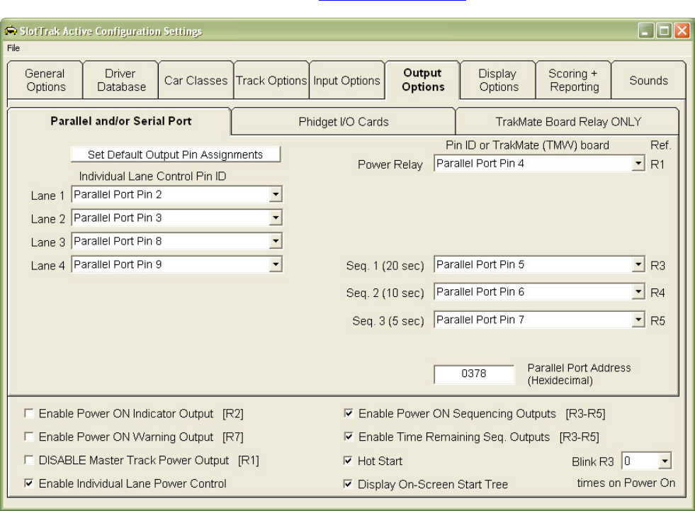
Output Options Tab Back to Table of Contents
Parallel and/or Serial Ports
1. The Power Relay may be controlled from the parallel or serial port, or the TrakMate card if in use. All other
control outputs may only use the parallel or serial port for this Output option. If TrakMate card id chosen, you
must select the relay wiring Normally Open or Normally Closed, and define the com port to be used to
communicate with the TrakMate card.
2. Enable/Disable Power On Indicator (R2). If a separate output is required when power is on, enable this. May be
required if a bypass switch is used on the power control to the track, making it unable to use the power relay
output for a power status indicator.
3. Enable/Disable Power ON Sequencing Outputs. These are a series of 3 outputs that can be used to indicate the
track power is going to be turned on by counting down like the christmas tree on a drag race start. R3 blinks the
count set in the dropdown list; followed by a 1-second wait followed by R4 turning on, followed by another 1-
second wait, then R5 is finally turned on. There are also ‘Sound Only’ options for sequencing. In this case, there
will be an on-screen indicator and a sound played. Sounds are also played if the relay outputs are enabled. If
sequencing is enabled, the following options are made available:
a) Choose the number of times to blink output R3 when start sequencing is enabled.
b) Choose the ‘Hot Start’ option to have the power turned on to the track before the start sequencing is
complete. Power is turned on at the beginning of the start sequence. This makes it possible for driver(s) to
jump the start. This could take place at the start of a Dash session, Race segments where all drivers start
from the start line and Race-off session start. When this option is enabled, the start line should be located
immediately before the track sensors.
c) If ‘Display On-screen start lights’ is checked, the start ‘Traffic light’ sequence is displayed on the computer
screen when power is turned on.
4. Enable/Disable Time Remaining sequence lights. The 3 outputs used for the Power ON Sequence may also be
used to indicate remaining time in a qualify, race, or race-off segment. Sequence Out 1 (R3) comes on when
there is 20 seconds left, Sequence Out 2 (R4) comes on with 10 seconds left, and Sequence Out 3 (R5) comes

19
on with 5 seconds left in the segment. If ‘Sound Only’ is defined, no relay outputs will be done. A sound will be
played, such as ’20 seconds left’, ‘5 seconds left’, etc.
5. Enable/Disable Power On warning. Activates this output pin (R7) for the length of time to perform the power on
sequence (depends on options selected) before power is turned on to the track. You can use a buzzer, flashing
light, etc. to make sure everyone is aware that power is coming on.
6. Each lane’s power can be controlled individually if the ‘Enable Individual Lane Power Control’ option is enabled.
The output to be used for each lane must then be defined in the same manner as above. This may be used for
dash or race segment finish options where the power is required to be turned off in an individual lane when the
car crosses the sensor area.
Phidget I/O cards
If Phidget cards are plugged into the USB ports (each card requires a USB port), SlotTrak will auto-detect the
cards and gather necessary information from each card such as serial number and number of outputs available
on the card. The card ID dropdown lists will list each card by serial number and card type (0/0/4, 8/8/8, 0/16/16).
When the card ID is defined, the Relay # dropdown list is filled with the appropriate number of outputs for the user
to choose from. Unfortunately, Phidget does not outwardly ID their cards. The serial number is read through
software only. If there is confusion on what card is what serial number, plug only one card in at a time before
running SlotTrak and note the serial number from the Card ID dropdown lists and mark the card with a label. You
must restart SlotTrak before switching plugged in cards. The auto-detect of Phidget cards is only done once
each time SlotTrak is started.
The 8/8/8 and 0/16/16 outputs are TTL level outputs, designed to drive SSR’s. The 0/0/4 card contains 5 amp
relays. Again, you can mix and match any of these cards, but may only have a maximum of four total cards.
If a TrakMate card is in use, the power relay may optionally be controlled by using the TrakMate card output. All
other outputs must be assigned to a Phidget card and relay number. If TrakMate card id chosen, you must select
the relay wiring Normally Open or Normally Closed, and define the com port to be used to communicate with the
TrakMate card.

20
TrakMate Board Relay Only
With the TrakMate Board Relay ONLY option, only main track power can be controlled by SlotTrak. All output
options that are NOT available with the TrakMate Only option are disabled. If additional outputs are required, use
the Parallel/Serial port option or the Phidget I/O card option in conjunction with the TrakMate board if you still
would like to use the TrakMate board to control the master track power relay.

21
Display Options Back to Table of Contents
1. Change the appearance, sizing, and screen position of the session displays. The Description / Example column
in the grid displays a sample of what it will look like. Clicking on a box in the Background or Foreground columns
brings up a color picker (if color is user settable). The sample will be updated when a color is chosen. Click on
one of the five Preview buttons to view a sample of the display. While the preview display is active, size and
position the display to your preferences.
2. Background Picture File: Specify a graphic that may be optionally displayed on the SlotTrak main screen. If
‘Picture Show’ is enabled, this setting is ignored. Suggested use would be a picture of your track. The image is
shown in the sample display box under the Browse button.
SSD Race Session uses the same sizing parameters and color selections as set for the Dash Display.

22
Scoring and Reporting Back to Table of Contents
1. Define the points structure for race, dash, and SSD race results.
2. If the Auto Print at end of race option is checked, the results are printed at the end of the race automatically.
All printing in SlotTrak is done to the default printer. You must have a default printer defined!
3. Check the Print at end of EACH segment to automatically print the race segment results.
4. If Auto Save is checked, the team competition points are saved in a file without prompting.
5. If section number input is checked, SlotTrak will prompt for race section number as each driver completes
the segment rotation (only if the segments are not terminated at the finish line – more on this later in race
setup). Depending on the number of drivers and lanes, this may be before the race is actually complete, as
some drivers may finish earlier than others. The section number is then used to break any ties in final
placings. If not enabled, the virtual section number is used to break ties, but the operator will have the option
to resolve any ties manually.
6. Set the default printer font name and font size. If the printed fields exceed the paper width, the printer font
size and font name will be adjusted to fit automatically by SlotTrak.

23
Sounds Back to Table of Contents
SlotTrak sound files are saved in the Sounds sub-folder under the application path. PCM wave files are used for
sounds. Many sound files are provided by the SlotTrak install. Users can also provide their own sound files.
Various sounds may be customized for different events in SlotTrak, which include lane triggers and fast lap
indicators, and the start sequence. Enable/Disable the sound options by checking/unchecking the check boxes
under Enable. Browse/locate any PCM .wav file by clicking the Browse buttons. The sound level may be adjusted
(decreased) for all of the Lane Trigger Sounds by moving the vertical scroll bar. This allows the ‘priority sounds’ to
be heard above the ‘lane trigger sounds’ when both sounds are playing simultaneously. On all sound selection
tabs, double-clicking the ‘Enable’ label will toggle the selection status for all sounds on that tab.

24
View/Print Qualify, Race, Dash, and SSD Race Results Back to Table of Contents
This menu function allows the operator to recall saved Qualify, Race, Dash, and SSD Race results, and also display
a recap of all races that have been run. Qualify, Race, Dash, and SSD race results and Laptime reports can be
printed to report files by clicking the ‘Make Report File’ function. There are two files that are created for each report.
File one is a simple text file that is created in the ‘Reports’ sub-folder with the same filename as the source session
filename, and has a file extension of ‘.doc’, so it can be opened in Word or WordPad. Use a true-type font such as
Courier so the text file displays properly. The second file is an HTML file that is created in the ‘Reports/HTML files’
sub-folder. It is named the same, but uses an HTML extension. This file can be viewed in any web browser and is
much more robust in the formatting since it does not rely on particular fonts for correct spacing. It is recommended
to use the HTML file to share results via e-mail or websites.
Scoring and Placing for Multiple Races Back to Table of Contents
This menu function provides the ability to compute total laps, place, and points values for a series of races. The
races to be scored are selected in a listbox. A resulting table is generated with the drivers that participated in at
least one of the races selected with the total laps, place, and the total points earned in the series of races selected.
The table can then be saved to both a comma delimited file (.csv) and a HTML file if desired. Both file formats are
always created. Double-click the multiplier in column 4 in the summary table on the top half of the screen to change
the multiplier value for that race.
Exit
Exit the program.

25
Session Menu
This is where the operator chooses the Session type to initiate. It should be noted that for ALL sessions (Practice,
Race, Qualify, Race-off, Dash, SSD Race, Team Comp), when the power is ON, the auto-resize feature of the
display form is turned off. Do not resize a form when the power is ON. Only the borders of the form will
change. None of the display controls will be resized to fit the form when power is ON!
Practice Session Back to Table of Contents
A Practice session is just that – designed for turning practice laps. Here’s a screen shot for a 4 lane track:
1. Current Lap times as well as fast laps are always displayed. If the display scale speed option is enabled in setup,
current scale speeds and fast scale speeds are also displayed. If scale speed is not enabled, the actual speed is
displayed. The scrolling list boxes display all of the lap times accumulated for each lane. The most current lap
time is always placed on the TOP of the list. The list will hold up to 200 lap times. After 200 lap times, the least
current (bottom of the list) time is removed from the list and the new lap time is added to the top of the list.
2. Lap counts for each lane are displayed directly above the Clear buttons.
3. The ‘Clear’ buttons under each lane’s lap count reset the fast time, clear the lap times listbox for that lane, and
reset the lap count to zero. F1-F8 designates the function key on the keyboard that will also perform this task if
you prefer not to use the mouse. ‘Clear ALL’ resets all lanes at once.
4. Minimum lap time is set at the specified default lap time defined in settings when Practice is entered, but may be
changed during the Practice session.
5. The power for all lanes may be toggled on/off by clicking the ‘Toggle Power’ button.
6. Track call, if enabled, will also toggle track power on/off.
7. Practice data is not saved in a file, but you can print the list of times by clicking the Print list button(s).

26
8. The boxes at the top default to the lane color text, but can be used to enter driver names for display and inclusion
into the printed stats report.
9. The SWAP button switches to an alternate practice screen:
Both practice displays are always active whether they currently show or not, and may be displayed at the
same time by resizing and repositioning each display on one CRT or displaying each individual display on
individual CRT’s if the computer is configured for multiple monitors.

27
Qualify Session Back to Table of Contents
A Qualifying session provides a method to time trial the cars one at a time to see who can turn the fastest lap.
Drivers may run in the lane of their choice, or a particular lane can be decided on before the qualifying session
is started. SlotTrak will automatically detect what lane is being used. Each driver turns laps for the defined
qualifying time, and the fastest lap time achieved is recorded for each driver.
Qualify Setup
1. When selecting drivers from the list, hold the Ctrl key or mouse button down while clicking to select multiple
drivers, or click while holding down the shift key to select a range of drivers from the list.
2. The listbox on the right is the order of qualifying for the drivers selected. Select a driver in this list and use the up
and down arrow buttons on the right hand side to define the qualifying order. Click Randomize Order to
randomize the qualifying order.
3. Qualify by elapsed time or define number of laps to be run.
4. Qualify Session Description is optional. When entered, the qualify results file will contain this description.
5. The car class is also optional. Again, this information is saved in the results file for future reference.
6. Optionally change the minimum lap time.
7. The ‘Load Last Configuration’ button will appear if there is a configuration file available. Every time a session is
started, the configuration is saved in a file. By clicking this button, the last settings, including driver selections, are
retrieved and set.
8. ‘Load Defaults’ will set the default settings for all items that apply.
9. Print Qualify Order prints the current defined qualify order to the default printer.

28
Qualify Display and Operation
Ties in qualifying are broken by the second fastest lap time for the tied drivers.
1. All Lap times are recorded in the list box on the right of the display, with most current lap time at the bottom of
the list.
2. The Pole lap time (upper right hand corner) is the current fast lap time for all drivers that have qualified. This
is the lap time that everyone is trying to beat.
3. Clicking Start or pressing the F8 function key will turn power ON (if power control is enabled). The session
can then be paused by clicking the Pause button, or pressing F8. Clicking the Continue button or pressing F8
will continue the segment.
4. Track Call, if enabled, will initiate the Start function when starting a segment and will Pause/Continue during a
segment.
5. Qualify results are saved in the Results sub-folder in a file. Each filename may be user defined and has a
‘.qua’ file extension. If the save lap times option is set, all lap times are written to a file of the same name, but
with a LapData_.csv filename extension.
6. Colors on this display are defined in the Settings function of SlotTrak. The display above uses the default
settings.
7. Click ADD Driver button (enabled between qualifying attempts) to add a driver on the fly to the qualify
session.
8. Click Delete Driver (enabled between qualifying attempts) to remove a driver from the qualify session
9. Click Skip Driver (enabled between qualifying attempts) to skip the current scheduled driver in the qualify
session. The skipped driver is re-scheduled to qualify at the end of the list.
10. Click Repeat Driver (enabled between qualifying attempts) to allow a ‘do over’ for the current driver.
11. Click Terminate to set the time to zero or laps remaining to zero if the driver wishes to end their qualify
attempt prematurely.

29
Race Session Back to Table of Contents
The Race session runs a segmented race. All drivers race in every lane for a designated amount of time or
designated lap count. SlotTrak keeps track of lane positions, lap counts, etc. as the drivers rotate through the lanes.
There are two segment options - timed or counted. Power is turned on and off by SlotTrak When a segment is
completed, drivers move their car to the next lane in the rotation (which is displayed on the race information screen) at
the track position where the car stopped, or brought back to the starting line if the terminate segment option is
enabled.
If individual lane power is enabled, and the terminate segment option is enabled in either the Counted or Timed
segment type, the power for each lane is turned OFF when the car in that lane completes their current lap after the
winner has been decided. If individual lane power is not enabled, the lap count will stop counting when the car
completes their current lap. Power remains on until each car completes their current lap. A ‘Terminate Segment’
button will appear on-screen to allow the operator to end the segment in case a car has malfunctioned and will not
complete its current lap.
Race Setup
Settings Tab
1. The race description and car class are optional. If defined, these values will be included in the results file.
Car class, if specified, will redefine the Minimum lap time and Coast time as defined for that class.
2. Select Lane Rotation Style (only available if 4 or more lanes). This defines how the cars are moved through
the lanes during a race. European rotation (recommended) mixes the lanes so drivers have different drivers
next to them in each segment. Custom allows you to enter your own rotation order. In the example shown,
the driver will sit out after running in lane 1 and lane 3. This allows you to eliminate lanes also if you choose
to do so. If ‘142’ is specified for example, lane 3 will not be used. One use for custom rotation is it allows a
rotation to be defined that will not fill all lanes, making extra corner workers available. Click the Rotation Tab
to display the entire race rotation if you are not sure what the order will be.
30
3. Choose Timed Segments or Counted Segments. Each type will define additional options pertinent only to
that race type.
For Timed Segments:
a) Segment length defines the length of each segment, in seconds. Maximum of 32000 seconds.
b) Off time between segments defines the amount of time between each segment. SlotTrak counts down
between segments based on this setting. When zero is reached, the power is turned back on and the
next segment is started. It is the responsibility of drivers to get their cars in position and be ready to race
before the segment is started.
c) If Disable Off Time Timer is checked, the timer countdown between segments in a timed race will be
disabled. The next segment will be started by the race director or track call.
d) The Termination method defines how each segment is ended:
¾ If Normal, the cars stop at the location on the track where they were when the segment time
decremented to zero and rotate from that location.
¾ If ‘Race to Line – at end of EVERY segment’ is selected, the cars continue to the start/finish
(sensor location). When the car crosses the lane sensor, if individual lane power is enabled
(Recommended!), the power is shut off for that lane. If individual lane power is not enabled, no
further laps are counted while the car continues to run. SlotTrak saves the time that it took the car
to reach the sensor from the time the segment counted down to zero time remaining. It then uses
these ‘time extensions’ to break any ties in finish order. All cars start at the start line at the
beginning of every segment using this method.
¾ If ‘End of Race - Race to line on Last Segment only’ is selected (option only available if
individual lane power control is enabled) the cars remain at their track location when the timer
counts down to zero for all segments except the last segment that they are on the track. The cars
start at their finish position on the track for the next segment. For each driver’s last on the track
segment, the power remains on until the car crosses the lane sensor. The time extension is again
saved and used to break any ties.
¾ If either ‘Race to line’ options are used, section number entry is disabled.
For Counted Segments:
a) Define the number of laps to be run before the segment is completed.
b) The Termination method defines how each segment is ended:
¾ If Normal, power is shut off when a car reaches the designated lap count and all other cars stop at
the location on the track and rotate from there.
¾ If ‘Race to Line – at end of EVERY segment’ is selected, all cars continue to the start/finish
(sensor location). When the car crosses the lane sensor, if individual lane power is enabled
(Recommended!), the power is shut off for that lane. If not enabled, no further laps are counted
while the car continues to run. SlotTrak saves the time that it took the car to reach the sensor from
the time the segment winner completed the designated number of laps. It then uses these ‘time
extensions’ to break any ties in finish order. All cars start at the start line at the beginning of every
segment using this method.
4. Define how many times in a row each rotation position is run. If 3 is chosen for example, each lane position
would be repeated 3 times in a row.
5. The Number of complete lane rotations defines how many times the complete lane rotation is run.
6. Minimum lap time and Coast time can be adjusted here, always in seconds.
7. The ‘Load Last Configuration’ button will appear if there is a configuration file available. Every time a race
session is started, the configuration is saved in a file. By clicking this button, all previous settings, including
driver selections, are retrieved and set.
8. The ‘Load Defaults’ button will load and define all of the default values that were specified in the configuration
settings.
9. The Points multiplier is used to ‘weight’ the race. The final point values for each driver are multiplied by this
value to determine a final point value.
There is a maximum of 32000 laps per segment in SlotTrak. Total Laps maximum is 2,147,483,647, but the
display is setup for a maximum of 5 digits or 99999. You can exceed 5 digits, but they might not all show. One
way to modify the number of digits shown is to resize the screen. By resizing, font size changes are made and
this may allow more characters to be displayed in the session display screens.
Drivers Tab

31
1. Define the drivers that will be participating in the race, and what lane they will be starting in. The quickest
way to accomplish driver selection is to use a qualify session results file. If none is available, a qualify file
can be created by clicking the Auto Qualify button or drivers can be selected from the master driver list by
clicking either Add Driver(s) to Race or Add/Replace Entrants from master Driver list buttons. When more
drivers than track lanes are selected, the driver(s) sit out before running lane #1 if using standard rotations,
or user specified if using Custom rotation. To manually place a driver into a lane or Sitout, the lane or Sitout
must be blank. Highlight the driver in the staging listbox and click the button next to the lane or sitout label
to move the driver into that position. Click the button next to the lane or sitout when a driver is defined to
remove the driver and place them back into the staging listbox.
2. Click the Rotate Lane Assignments to rotate the lane positions according to the rotation option selected
previously in the Settings tab.
3. Re-Stage ALL removes all drivers from the assigned lanes and sitouts and lists them in the staging listbox
so the operator can redefine each drivers start position to something other than the default.
4. The Sitout order determines when the driver comes on to the track with respect to other drivers that are also
out. Sitout 1 will come on the track first.
5. ‘By Qual Rank’ puts ALL drivers in the staging listbox into Sitouts by order of qualifying position.
6. ‘Random’ puts ALL drivers in the staging listbox into Sitouts in a random order.
7. ‘Clear All Sitouts’ removes all drivers from the sitout order and places them back into the staging listbox.
8. ‘Add River(s) to Race’ brings up the master driver list and allows the operator to add additional driver(s) to
the heat without changing the current order and placings of the already selected drivers. Driver removal is
not possible with this option.
32
9. ‘Add/Replace Entrants from master Driver list’ allows the operator to choose drivers from the master driver
list to define which drivers are going to be in the race, and not have to use Qualify or Auto-qualify results.
The driver order is randomized when this option is used.
10. If ‘Add Drivers to Race Staging ONLY’ is checked, all drivers added to the Race Entrants listbox will be
placed into the Race Staging listbox only, and will not be placed into Lanes or Sitouts. The operator would
then be required to place the drivers manually into the proper lane or sitout.
11. Optionally, select the driver that is the top qualifier for this race.
12. Saved Qualify sessions listbox contains the qualifier sessions that are currently saved on the computer in
the results folder. They are sorted when listed with the most current file at the top. Double-click to select a
saved qualify session and load the results. The drivers that participated in the qualify session will be placed
in inverted order in the race entrants list. You can then select drivers from the race entrants listbox and
they will be selected and seeded according to qualifying order.
13. The Auto Qualify option creates a ‘fake’ Qualify results file with the drivers chosen from the master driver
list. This allows the race setup features that use the Qualify results to be used even if there was no Qualify.
If there is not enough time to run a Qualify session, use this option to speed race setup. The driver order is
randomized when using this option.
14. By default, when multiple heats are required based on the lane count and number of drivers, SlotTrak will
attempt to setup heats from slowest to quickest. SlotTrak will force the fast heats to contain the same
number of drivers as lanes, and the slowest heat will contain all of the ‘extra’ or ‘odd’ drivers. For example,
if there are 19 drivers and 4 heats with 4 lanes, heat 1 will contain 7 drivers and the rest of the heats will
contain 4 drivers. If the ‘Force Number of Drivers’ option is checked, SlotTrak will instead try to create heat
definitions that have an equal number of drivers, or as close as possible to equal.
15. If a qualify session it selected, you can set up number of heats, heat number, and bracket. Bracket allows
some flexibility when setting up heats. Experiment with it to see what effect it has. Using the Qualify
results makes setting up a race much easier and quicker – use this feature!!
16. The Add Name button allows driver(s) to be added to the master driver list without having to go back to the
Settings/Configuration screen.
Setup note: If you define a heat or heats that are different than the SlotTrak determined heat configurations,
make sure you store the heat configurations. If you don’t, the next heat when chosen from the heat number drop
down list will be configured as SlotTrak would want to configure that heat without knowledge of the previous
heat’s configuration. For example, if you would define a 2 heat race with 12 drivers in heat 1 and 6 drivers in
heat 2 for a 4 lane track, that’s fine but when heat 2 is selected, SlotTrak has no knowledge of the fact that you
defined 12 drivers in the first heat and will create heat 2 with either 4 drivers [number of lanes] if Force is not
selected, or 9 [total drivers (18) / number of heats (2)] drivers if ‘Force…’ is selected. Bottom line – save your
custom heat configurations in files by clicking on the Store Current Heat button!!

33
Rotation Tab
This table shows the complete lane rotation sequence and may be printed.

34
Resume Race Tab
If required, this option allows a race to be restarted at a specific segment number. A list of available race files is
displayed. The list is sorted with the most current race file on top. Double-click the desired race file. The number
of segments completed will be displayed. Choose the Segment number to begin Race Resume. This is the
segment number that the race will be started at. Any previous segment’s results will be retained in the race
results.

35
Team Competition Tab
This option allows the setup of a race between two teams. The teams may consist of 2 to 10 drivers. An equal
number of drivers from each team must compete. Drivers from the same team are never next to each other on the
track. A straight rotation is always used for team competition. Click ‘Define Teams and Members’ to define Team
names and the drivers on each team, along with the default starting position for each driver. The defined teams are
listed in the dropdown lists and are chosen from the lists. When all selections and definitions are complete, click the
‘Enter Teams In Race’ button to enter the team drivers into a race. When entered, items such as rotation style
(straight) and Counted race (with terminated segments) are set. The team race is a points race and points must be
enabled and defined to run a team race. Use the Load and Save Team Race Config buttons to Load or Save this
race configuration. This saves every defined parameter required to setup and run a race, just as the Race
configuration or Store Heat functions will do, but allows the operator to name the saved configuration file.

36
Race Display and Operation
There are two displays associated with the Race Display. The Segment display:
1. The race segment display is in order of current segment standing. The leader (red lane) is on top so a
quick glance at the display indicates red in the lead for the segment.
2. Click on the column header to change the display option for that column. Total pts or Total laps may be
displayed in column 3. Fast Lap, Median lap time, or Lag behind Leader or Trail behind position may be
displayed in column 4. Lag is the time or # laps behind the current segment leader. Trail behind
position is the time or # laps behind the car in the next highest position. Median is NOT an average, it is
the lap time that half of the laps run for that driver are above that time and half are below that time.
3. These settings are saved so the next time a race is run, the display options start out as how they were
last defined.
4. Right-click the lap time display label to display a list all lap times for that lane.
5. Double-click the name or lap count to adjust the number of laps. This can only be done when the power
is OFF (paused).

37
The field summary display that is available during pauses or between segments:
The counted session displays are very similar, without the time remaining indicators in the display.
1. Colors on this display are defined in the Settings function of SlotTrak. The display above uses default settings.
2. The scroll bar under Display allows the user to scroll back to different segment numbers as the race progresses.
This is enabled during the countdown/pause between segments. Don’t worry about setting it back to the proper
segment. That will be done automatically when the segment starts. When the race is complete, the scroll bar is
enabled again to allow review of all of the race segments.
3. Command button text shows the function key that will perform the same task as clicking that button if you prefer
not to use the mouse.
4. The Start Race button will begin the race. Power will be turned on.
5. The Pause button will turn the power off and stop the timer from counting down. SlotTrak continues to count
laps for the specified Coast Time (in seconds) after EVERY Race, Dash, Race-off, Practice or Qualify
power shutdown, so cars coasting across the detection sensors will still get credited for their lap and lap time.
A paused state is indicated by the blinking ‘TIME REMAINING’ caption during a timed race.
6. Continue button will continue the race after a Pause and power will be turned back on.
7. Pause Countdown button will pause the countdown that is counting to the beginning of the next segment. Again,
the ‘TIME REMAINING’ caption will blink during a paused countdown (timed race only).
8. Continue Countdown button will re-enable the countdown to the next segment (timed race only)
9. Skip Countdown will cause the next segment to be started immediately.
10. Abort race will stop everything – the race up to the time it is aborted is saved in the race results file for possible
resumption. SlotTrak returns to the race setup screen when this option is executed.
11. The race results file is saved in the Results sub-folder. The filename will have a ‘.rac’ file extension, and are
named by the user.
12. Double-click the Driver Name label or the lap count display to adjust the number of laps for any active driver.
This may be done during a paused segment or between segments.
38
13. The Lap Times button brings up a display of every lap time for every driver in the race. From this screen, you
have the option to print or save the information in a file.
14. Double-click the lane label between segments to display the last computed virtual track position for the driver
selected.
15. Track Call, when enabled, will perform the following functions:
¾ With Start Race button displayed, track call will start the race.
¾ With Pause button displayed, track call will perform the Pause function.
¾ With Continue button displayed, track call will perform the Continue function.
¾ During countdown between segments, track call will perform the Skip function.
When the race is complete, additional option buttons will appear to allow printing of the race results and if team
competition is enabled, print and save of the team points information.
The Toggle Display buttons switch between the field summary display and the race segment display. Switching
between the two displays never alters any of the countdown timing.
The Print Lap Times button allows the operator to display all lap times for every lane run for every segment. From
that display, the options to print and save are available.
If the ‘Prompt to enter section numbers’ option is checked in settings, as each driver finishes the segment rotation, the
section number on the track is prompted for and entered into SlotTrak. Depending on the rotation/number of drivers,
this may occur before the end of the race. This section number is then used as a tie-breaker. Of course, if the
segments are terminated, the section number is meaningless because all cars cross the finish line.

39
Dash Session Back to Table of Contents
The Dash session performs a lap counted race (as opposed to a timed race) where each driver runs in a defined lane
for the entire race. The amount of Dash laps is specified in setup. The first driver to reach the defined number of laps
is the winner.
If Individual Lane Power is enabled, the power for each lane is turned OFF when the car in that lane completes the
current lap it is on when the winner is decided. If Individual lane power is not enabled, the lap count will stop counting
when the car completes the lap it is on when the winner is decided and track power is left ON until all cars finish. A
‘Terminate Segment’ button will appear to allow the operator to manually end the dash in case a car has
malfunctioned and will not finish.
Dash Setup
1. Dash description and car classes are again optional.
2. Define the total number of dash laps.
3. Minimum lap time is initially set at the default value in settings. Choosing a car class may change this value.
Otherwise, a new value can be typed in the input box.
4. Coast time is initially set at the default value in settings. Choosing a car class may change this value.
Otherwise, a new value can be typed in the input box.
5. Driver selection is completed in the same manner as race setup. Refer to race setup for a description of driver
selection. The maximum number of drivers in a dash is equal to the number of lanes on the track.

40
6. The ‘Load Last Configuration’ button will appear if there is a configuration file available. Every time a session
is started, the configuration is saved in a file. By clicking this button, all previous settings, including driver
selections, are retrieved and set.
7. Saved Qualify sessions listbox contains the qualifier sessions that are currently saved on the computer in the
results folder. They are sorted when listed with the most current file at the top. Double-click to select a saved
qualify session and display the results. The results are displayed in the Qualify Results listbox. You can also
select drivers from the results listbox and they will be selected and seeded according to qualifying order.
8. Refer to the Auto Qualify reference in race setup for an explanation of this function.
9. The Points multiplier is used to ‘weight’ the race. The final point values for each driver are multiplied by this
value to determine a final point value.
Dash Display and Operation
1. Start Dash button starts the dash and power is turned on to the track.
2. Abort Dash button stops the dash and returns to the main SlotTrak screen.
3. Pause button turns the power off. Again, SlotTrak counts for Coast time seconds (user defined) after the power is
turned off to make sure cars coasting across the counters will be credited with their lap.
4. Continue button turns the power back on.
5. The Dash results are saved in a file in the Results sub-folder. The filename will have a ‘dsh’ extension, and is
named by the user.
6. Double-click the Laps or driver display labels during a paused dash to adjust the number of laps for any driver.
Lap adjustments must be done before the Dash is complete.
7. Colors on this display are defined in the Settings function of SlotTrak. The display above uses the default
settings.
8. The lap count display on the right indicates the current placing in the race by order of lane color. The leader (red
lane) is on top so a quick glance at the display indicates red in the lead.
9. Right-click the lap time display label to display a list all lap times for that lane. Power must be off for this function
to be enabled.

41
The Dash finish does not turn the power off to the entire track when the winning driver accumulates the defined
number of laps. SlotTrak leaves the power on for all lanes that have not crossed the finish line in an attempt to
determine all other driver/car placings. If individual power control is enabled, power will be turned off for each lane
when the car crosses the line on their current lap. When all drivers have crossed the finish line, the track power is
turned off. A ‘Terminate Segment’ command button will appear while SlotTrak is waiting for all cars to finish. If a car
has malfunctioned and will not cross the line, click the ‘Terminate Segment’ button to end the Dash. There are never
ties using this method.
When the dash is complete, the field summary display will appear:

42
Scalextric Sport Digital (SSD) Race Session Back to Table of Contents
The SSD session is similar in many ways to the Dash session. It is possible to run up to 8 lanes (4 power bases)
using this option for a total of 24 cars maximum. There are two different finish options with SSD. The tool tip that is
displayed when the cursor is placed over the End Lap options explains the two different finish options and how they
operate.
The major difference between a SSD session and all others is the lack of ability to remotely program or command the
power base unit. The power base transmits only, and will not act on any received characters (commands sent from the
computer). Therefore, it is the responsibility of the operator to correctly setup the parameters in both SlotTrak and the
SSD power base unit(s) to run a race properly. The number of race laps designated on the SSD setup screen in
SlotTrak must be equal to the programmed number of laps on the power base if the SSD power control option
is enabled in settings (only applicable for two lane – single power base setups).
43
Scalextric SSD end race options:
End at SAME Lap - when the leading car passes the Sport Digital power base Finish Line at the end of the final
lap, the race finishes for this car and all other cars as they complete their CURRENT lap.
End at LAST Lap - the race finishes for each car as it completes its final lap. The race finishes when all cars have
completed their FULL number of laps.
Auto Qualify – when using Auto Qualify in SSD mode, SlotTrak will only allow the maximum number of digital entries
(for example 12 drivers for a 4 lane/2 Power base setup) to be selected. In other words, only one heat may be defined.
If you select more than the maximum, the driver selection is truncated. You will be prompted to enter the digital ID for
each of the drivers selected. Whenever this qualify file is loaded in the SSD race setup, the digital ID that was defined
in the auto qualify settings screen will be assigned to the associated driver.
Note: the above applies to auto qualify only. If you run a normal qualify session and import that file in SSD setup, all
drivers are imported into a possible multiple heat race and you will be required to assign the proper digital ID 1 to ?.
The above screenshot illustrates this. The saved qualify file for 15 drivers was imported (actually this file is an auto
qualify file from a non-SSD race) and multiple heats are configured.
Refer to the Dash setup instructions for clarification on all of the other settings.
There are two different ways that a SSD race can be implemented.
1. Leave all power base units in power-up state and let SlotTrak do most of the work. This is definitely the
easiest way to run a race. There is no programming or setup required on the power base. All power bases
are left in practice (power-up state) mode. SlotTrak will determine who won the race and finish order. The
only drawback to this method is the power may be left on at the end of the race (unless you enable the
external power control in SlotTrak). Counting and timing for each individual car will stop when that car has
been determined to have finished the race, but the cars may continue to operate, depending on the power
control options specified.
2. The power base can be used to turn the power on at the start of a race, and optionally turn the power off for
each car as it finishes or turn power off at end of race. There are two ways to start a race in this mode (see
input settings for Scalextric Sport Digital for further explanation):
• Use the start button on the power base to start a race. SlotTrak waits for the start command to be issued
by the power base(s) and begins to count and time after the start command is received. If the start tree is
enabled, it is displayed with red lights initially. The lights turn yellow when the start command(s) are
received from the power base(s). When the power is actually turned on (after the power base
countdown), the lights turn green.
• Use the ‘SlotTrak Start Button to start race’ option to start a race. The start button is pressed on the
power base to initiate the start sequence, but the race does not actually start until the start button on the
SlotTrak display screen is clicked (or F8 is pressed) and, if the start tree is enabled, the countdown from
the on-screen start tree completes. The power base turns the power on, the start command is received
by SlotTrak through the interface, and the ‘Start Race’ button on the SlotTrak screen display becomes
visible. Power is now turned on to the track, but if a driver leaves before the ‘Start Race’ button is
pressed and the on-screen countdown finishes, lap triggers are ignored and the driver(s) are basically
penalized a lap for jumping the start because the lap did not count. Make sure to line the cars up right
before the sensors when this option is enabled. You must check ‘Use SlotTrak Start button to start race’
option in Scalextric SSD input settings to enable this start option.
SlotTrak still counts and times laps and displays the running order in the race as always, but also synchs itself
to the race by interpreting the power base ‘race over’ command. SlotTrak also displays any false start
indicators if they are enabled on the power base for this option.
In either case, SlotTrak NEVER counts laps for cars that it has determined to have completed the designated number
of laps, or depending on the end option selected, have completed their current lap after a race winner has been
established. The cars may remain running depending on the power control option used, but no additional laps or lap
times will be recorded for those car(s).
The SSD race display is the same as the Dash session, with the addition of the optional false start indicator.

44
Race-Off Session Back to Table of Contents
Race-Off is a two-segment match race between two drivers. Each driver selects a lane to start in. The first
segment is started and runs for the specified segment length. At the end of the first segment, the drivers swap
lanes, putting their cars in the other’s lane at the track position that their own car stopped at. The second segment
is then completed. One use for Race-off is to resolve ties in races. Any match race can be setup using Race-off.
Race-Off Setup
Setup is self-explanatory. Two drivers and what lanes they will start in are specified in the dropdown lists, along
with a segment length and minimum lap time. There is no timer countdown between segments in a race-off.
Results are not saved for a Race-off.

45
Race-Off Display and Operation
1. The same functionality described in the Timed Race session applies to the Race-off session. Race-off results are
not saved in a file.
2. Double-click the Segment Laps display label or driver name label during a segment pause to adjust the number of
laps for one of the two drivers.
3. Right-click the lap time display label to display a list all lap times for that lane.

46
Help Menu Back to Table of Contents
About Menu
The About Menu selection will display the splash screen that popped up when SlotTrak was started. The
revision number of the program and assorted computer hardware parameters are displayed.
Register Menu
SlotTrak is Trialware. Registration cost is $99 for the regular version, and $149 for the commercial version which
includes the time sell feature. When not registered, the program is fully functional, but the following restrictions
are implemented:
• Race segment length is limited to 20 seconds
• Counted segments are limited to 3 laps
• Practice sessions display a message after 3 minutes
• Qualify is limited to 15 seconds
36 days from the software install date, SlotTrak becomes unusable if not properly registered. After 36 days of
unregistered use, the only enabled function is software registration. The ‘Evaluate SlotTrak’ button disappears
and all session types are disabled.
SlotTrak is keyed to the particular computer it is installed on, and requires a unique registration key for each
individual computer. The software code is required to generate a valid key, which will register the program.
Follow the instructions on the registration screen. To pay, use PayPal with the e-mail address
SlotTrak@fsmra.com. Send the software code to the same e-mail address (displayed on the registration
screen). When you receive the key, you have two options to register the program:
1. Enter the registration key in the Registration key text input box and then click the ‘Register SlotTrak’
button. It is best to cut-and-paste the key to ensure the key is not mistyped.
2. Place the entire key file that you receive into the SlotTrak application folder (the folder/directory where
SlotTrakXXX.exe resides – normally c:/Program Files/SlotTrakXXX) and run SlotTrak. The program will
register automatically. This is definitely the easiest and best way to register the program.
Don’t lose the key – something may happen on your computer (hardware failure, virus, etc.) that will require a
software re-install and re-registration. The key is entirely numeric, so case sensitivity is not an issue.
If you have SlotTrak questions, confused about content of this manual, or have suggestions, e-mail me at:
