
OWNER MANUAL
Revised 8/6/2018
541-624-5500
62582 Pierce Rd.
La Grande, OR 97850

Table of Contents
INTRODUCTION
. . . . . . . . . . . . . . . . . . . 1
Owner Manual & Info Packet . . . . . 1
Reporting Safety Defects . . . . . . . . 1
Safety Information . . . . . . . . . . . . . 2
WARRANTY
. . . . . . . . . . . . . . . . . . . . . . . 3
Outdoors RV 1−2−3 Warranty . . . . . 3
Warranty Exclusions . . . . . . . . . . . . 3
Owner Responsibility . . . . . . . . . . . . 4
Dealer Responsibility . . . . . . . . . . . . 4
Outdoors RV Responsibility . . . . . . 4
Warranty Disclamers . . . . . . . . . . . . 4
In Matters Of Dispute . . . . . . . . . . . 4
Component Product Registration . . . 5
How to Obtain Warranty Service . . . 5
Pre−Delivery Inspection . . . . . . . . . . 6
Owner Registration . . . . . . . . . . . . . . 6
Getting to Know Your RV . . . . . . . . 6
Making an Appointment . . . . . . . . . . 6
Inspecting Repairs . . . . . . . . . . . . . . 7
ON THE ROAD
. . . . . . . . . . . . . . . . . . . . . 8
Guidelines for Equipment Selection . 8
Operator Licensing Requirements . . 10
Hitching Up . . . . . . . . . . . . . . . . . . . 10
Braking System . . . . . . . . . . . . . . . . 13
Loading Your RV . . . . . . . . . . . . . . . 15
Hitch Receivers . . . . . . . . . . . . . . . . 17
Distributing your Load . . . . . . . . . . . 17
Safe Driving Guidelines . . . . . . . . . . 22
Tire Safety and Information . . . . . . . 25
Wheel Lug Nut Torquing . . . . . . . . . 31
Pre−Departure Checklist . . . . . . . . . . 33
LIVING WITH YOUR RV
. . . . . . . . . . . . 35
Fire Safety . . . . . . . .. . . . . . . . . . . . . 35
Effects of Long−Term Occupancy . . 37
Leveling and Stabilization. . . . . . . . . 43
Window Coverings . . . . . . . . . . . . . . 45
Dinette Conversion . . . . . . . . . . . . . . 46
Sofa Conversion . . . . . . . . . . . . . . . . 47
Storage Compartments . . . . . . . . . . . 48
Entry Doors, Screens and Locks . . . 49
PLUMBING SYSTEMS
. . . . . . . . . . . . . . . 50
Fresh (Potable) Water System . . . . . 50
Sanitizing Fresh Water System . . . . 56
Waste Water System . . . . . . . . . . . . 56
Plumbing Systems Awareness . . . . . 60
ELECTRICAL SYSTEMS
. . . . . . . . . . . . 62
120 Volt AC System . . . . . . . . . . . . . 62
12 Volt DC System . . . . . . . . . . . . . . 66
The RV Battery . . . . . . . . . . . . . . . . . 68
Solar . . . . . . . . . . . . . . . . . . . . . . . . . 70
Bulbs and Fuses . . . . . . . . . . . . . . . . 71
PROPANE SYSTEM
. . . . . . . . . . . . . . . . . 72
Propane Safety . . . . . . . . . . . . . . . . . 72
System Components . . . . . . . . . . . . . 74
Filling Propane Tanks . . . . . . . . . . . 77
Propane System Checks . . . . . . . . . . 78
Propane Leak Detector . . . . . . . . . . . 78
Lighting Propane Appliances . . . . . . 80
APPLIANCES AND EQUIPMENT
. . . . . 81
Furnace . . . . . . . . . . . . . . . . . . . . . . . 82
Water Heater . . . . . . . . . . . . . . . . . . . 82
Water Pump . . . . . . . . . . . . . . . . . . . 83
Refrigerator . . . . . . . . . . . . . . . . . . . 83
Range/Oven/Cooktop . . . . . . . . . . . . 83
Range Hood . . . . . . . . . . . . . . . . . . . 83
Microwave/Convection Oven . . . . . 83
Fireplace . . . . . . . . . . . . . . . . . . . . . . 84
Air Conditioner . . . . . . . . . . . . . . . . . 84
Thermostat . . . . . . . . . . . . . . . . . . . . 85
TV/Stereo Antenna . . . . . . . . . . . . . . 85
TV/Satellite Connections . . . . . . . . . 85
Televisions . . . . . . . . . . . . . . . . . . . . 87
Awning . . . . . . . . . . . . . . . . . . . . . . . 87
Slide−Out Topper . . . . . . . . . . . . . . . 88
Power Roof Vents . . . . . . . . . . . . . . 88
Manual Roof Vent . . . . . . . . . . . . . . 88
Rear Monitor Camera . . . . . . . . . . . . 88
Heated Holding Tanks . . . . . . . . . . . 88
Monitor Panel . . . . . . . . . . . . . . . . . . 89
Propane Leak Detector . . . . . . . . . . . 89
Carbon Monoxide Detector . . . . . . . 89
Smoke Detector . . . . . . . . . . . . . . . . 91
Wireless Function Controller . . . . . . 91
Spare Tire Carriers . . . . . . . . . . . . . . 91
Slideout Room . . . . . . . . . . . . . . . . . 92
Toy−Lock . . . . . . . . . . . . . . . . . . . . . 95
Battery Tray . . . . . . . . . . . . . . . . . . . 95
Tongue Jack . . . . . . . . . . . . . . . . . . . 96
Manual Stabilizer Jacks . . . . . . . . . . 96
Electric Stabilizer Jacks . . . . . . . . . . 96
Automatic Leveling System . . . . . . . 96
Flow−Longer LP Gas Line Kit . . . . . 96
LP Generator . . . . . . . . . . . . . . . . . . 97

Table of Contents
STORAGE & WINTERIZATION
. . . . . . 108
Storage Checklist . . . . . . . . . . . . . . . 108
Winterization . . . . . . . . . . . . . . . . . . 109
Reactivating RV After Storage . . . . . 111
MAINTENANCE
. . . . . . . . . . . . . . . . . . . . 113
Exterior . . . . . . . . . . . . . . . . . . . . . . . 113
Interior . . . . . . . . . . . . . . . . . . . . . . . 120
Maintenance Schedule . . . . . . . . . . . 124
Maintenance & Repair Log . . . . . . . 125
THE RV TOOL BOX
. . . . . . . . . . . . . . . . . 126
OWNER NOTES
. . . . . . . . . . . . . . . . . . . . 127
RAMP MODEL FEATURES
See Addendum (if applicable)
STORAGE & WINTERIZATION
. . . . . . 97
Storage Checklist . . . . . . . . . . . . . . . 97
Winterization . . . . . . . . . . . . . . . . . . 98
Reactivating RV After Storage . . . . . 100
MAINTENANCE
. . . . . . . . . . . . . . . . . . . . 101
Exterior . . . . . . . . . . . . . . . . . . . . . . . 102
Interior . . . . . . . . . . . . . . . . . . . . . . . 108
Maintenance Schedule . . . . . . . . . . . 110
Maintenance & Repair Log . . . . . . . 111
THE RV TOOL BOX
. . . . . . . . . . . . . . . . . 112
OWNER NOTES
. . . . . . . . . . . . . . . . . . . . 113
RAMP MODEL FEATURES
See Addendum (if applicable)

1
Introduction
Outdoors RV Manufacturing appreciates and welcomes you as a customer. We want your RV purchase
and camping experience to be most enjoyable for many years to come! We have provided this Owner
Manual so that you and your family will be able to make the most out of your camping experience.
Your new RV has been constructed to conform with or exceed Federal and State safety regulations.
Quality assurance methods and/or functions meet or exceed standards prescribed by ANSI/NFPA 1192
and/or CSA Z240 as approved by the agency having jurisdiction in the United Sates or Canada.
We thank you for your purchase!
Outdoors RV Manufacturing
P.O. Box 1047
62585 Pierce Road
La Grande, OR 97850
Phone: 541-962-1866
Fax: 541-962-1894 (Parts & Service)
Website: http://outdoorsrvmfg.com/
Facebook: https://www.facebook.com/outdoorsrvmfg/
OWNER MANUAL AND INFORMATION PACKET
To help you get started please make time to read and review this Owner Manual. This information will
help provide you with many of the functions and required maintenance procedures necessary on your
RV. Your RV will require regular care and maintenance in order to deliver maximum value and
performance. Your dealership will provide you basic operating and maintenance instructions. However,
be sure to read all instructional materials and equipment manuals located in your Owner Information
Packet included with your new RV. Many of these manuals are also available as free downloads at each
product manufacturers website in the event that something may be missing from your packet. You may
also visit our website for a free download of this manual.
Some components in this manual or packet may be components of a differing product line or are
optional equipment in which case will be noted as 'If Equipped'. Product specifications, design and
equipment may change without notice due to continuous product improvement by Outdoors RV. It is
possible that recent product changes may not be included in this manual. Product information included
in this Owner Manual were as accurate as possible at the time of publication and may or may not be
specific in their depiction of actual equipment, fabrics, interior, or exterior decor or design options as
installed on or in your RV. This manual is subject to change without notice.
REPORTING SAFETY DEFECTS
If you believe that your vehicle has a defect which could cause a crash or could cause injury or death,
you should immediately inform the National Highway Traffic Safety Administration (NHTSA) in
addition to notifying Outdoors RV Manufacturing. If NHTSA receives similar complaints, it may open
an investigation, and if it finds that a safety defect exists in a group of vehicles, it may order a recall and
remedy campaign. However, NHTSA cannot become involved in individual problems between you,
your dealer, or Outdoors RV Manufacturing.

2
Introduction
To contact NHTSA, you may call the Vehicle Safety Hotline toll-free at 1-888-327-4236 (TTY: 1-800-
424-9153); go to http://nhtsa.safercar.gov; or write to: Administrator, NHTSA, 1200 New Jersey
Avenue SE, Washington, DC 20590. You can also obtain other information about motor vehicle safety
from http://www.safercar.gov
.
SAFETY INFORMATION
Shown below are various hazard warnings you will find throughout this manual. They are used to alert
you to potentially dangerous or hazardous situations. When you see these symbols, please read them
carefully, and follow their instructions to help prevent damage to your recreational vehicle and for your
personal safety as well as others nearby.
DANGER indicates an immediately hazardous situation that, if not
avoided, will result in death or serious injury.
WARNING indicates a potentially hazardous situation that, if not
avoided, could result in death or serious injury.
CAUTION indicates a potentially hazardous situation that, if not
avoided, may result in minor or moderate injury.
NOTICE is used to address particularly important information that is
not necessarily injury related and may include situations involving
property damage or issues which may void warranty.

3
Warranty 1 of 2
OUTDOORS RV 1−2−3 WARRANTY
1 Year - Limited Bumper to Bumper Warranty - Transferable
Outdoors RV Manufacturing warrants for a period of one (1) year from the date of purchase that the RV manufactured and assembled by Outdoors RV
Manufacturing shall be free from defects in materials and workmanship supplied and attributable to Outdoors RV except as specifically excluded below. If a
defect occurs within the first year please contact an Outdoors RV Mfg. authorized dealer and schedule an appointment for an inspection of the defect.
Outdoors RV Mfg., at its sole discretion, reserves the right to substitute parts or components of substantially equal quality, touch-up cosmetic flaws, make
design and or manufacturing improvements as the remedy under this Limited Warranty. All owners (original or subsequent) must be properly registered with
Outdoors RV Manufacturing to be considered for eligibility.
This Limited Warranty may be transferred during the one (1) year term by the original owner to a subsequent purchaser. The limited one (1) year warranty,
however, shall in no way be extended beyond the one (1) year from the original date of purchase by reason of the transfer from the original consumer
purchaser to any subsequent purchaser(s). The subsequent purchaser(s) also has an obligation to notify Outdoors RV Mfg. immediately upon the transfer of
the warranty and to provide proof of purchase within the one (1) year.
2 Year - Limited Structural Fiberglass Wall Warranty - Non Transferable
A customer must have followed the maintenance section of the owners manual and provide documentation of exterior roof, window, door, luggage doors,
and moldings seal maintenance along with proper fiberglass care maintenance to an Outdoors RV Mfg. authorized dealer in order to be considered for the
fiberglass wall warranty. The best method for proper documentation is to have your local authorized Outdoors RV dealer perform the inspection and work
for you. If a structural fiberglass defect occurs after the first year and within the second year please contact the Outdoors RV Service Department in La
Grande, OR to schedule an appointment at the factory for an inspection of the defect. You will be responsible for transporting the RV to and from the factory
in La Grande, OR. If correct maintenance was performed and documented properly and the defect is valid, Outdoors RV Mfg. will authorize the repair at the
factory in La Grande, OR at no expense to the customer (Travel costs not included).
3 Year - Limited Custom Built Chassis Warranty - Non Transferable
A customer must have followed the maintenance section of this owners manual and provide documentation from an Outdoors RV Mfg. authorized dealer of
the following: Inspection of the chassis hardware (regularly tighten as necessary) along with maintenance records of proper care of the trailer A-frame,
bumper and overall chassis in regards to cleaning, and touch-up paint, to be considered for the chassis warranty. If a chassis defect occurs after the first year
and within the third year please contact the Outdoors RV Service Department in La Grande, OR to schedule an appointment at the factory for an inspection
of the defect. You will be responsible for transporting the RV to and from the factory in La Grande, OR. The best method for proper documentation is to
have your authorized Outdoors RV Mfg. dealer perform the inspection and work for you. If correct maintenance was performed and documented properly
and the defect is valid, Outdoors RV Mfg. will authorize the repair at the factory in La Grande, OR at no expense to the customer (Travel costs not included).
WARRANTY EXCLUSIONS
This Limited Warranty and the obligations stated herein shall not apply to:
1. RVs used for business, rental, commercial, or disaster relief purposes other than recreational travel and family camping.
2. RVs which are not originally sold through an authorized Outdoors RV Mfg. dealer (i.e. sold through auction, repossession, and salvage or
otherwise 'distressed' condition).
3. Equipment, products, components, appliances, or accessories not manufactured or installed by Outdoors RV Mfg. whether or not warranted,
including but not limited to, tires, batteries, and other installed equipment or accessories.
4. Damage or loss caused in whole or part by misuse, abuse, neglect, theft, vandalism, RV modification, improper customer or dealer installation,
incorrect line voltage, unauthorized repair or failure to follow instructions supplied with the recreational vehicle.
5. Damage or loss caused in whole or in part by any unauthorized attachments, modifications or alterations to the structure, body, pin-box, or frame
of the recreational vehicle including but not limited to trailer hitches for towing, or platforms for supporting cargo.
6. Any upholstery damage including, but not limited to tears, punctures, or misuse.
7. Any fading or discoloring of fabrics, carpet, or flooring roll goods.
8. Routine maintenance including, without limitation, caulking, re-caulking, and waxing of the body of the recreational vehicle, tightening screws,
brake adjustments, latches, locks, changing fuses, or light bulbs, and maintaining the air conditioning and heating systems.
9. Damage or loss caused in whole or in part by exposure to natural atmospheric elements, corrosive chemicals, ash, or fumes generated or released
by vehicles, collision, road hazards, rock chips, condensation, or any other source.
10. Damage or loss caused in whole or in part by overloading or the improper balancing of the load.
11. Damage or loss to the recreational vehicle caused in whole or in part by the tow vehicle selected by the owner to pull the recreational vehicle
including but not limited to the improper selection or installation of the towing hitch on the tow vehicle.
12. Damage or loss caused in whole or in part by the willful or negligent acts of the driver of the vehicle pulling the recreational vehicle, an accident
involving the recreational vehicle caused by the condition of any road surface over which the recreational vehicle is pulled, or striking over a curb
or any other object.
13. Any injury, loss, or damage due to mold or fungi.
14. Any incidental and consequential damages including but not limited to transportation, fuel, food, lodging, telephone calls, towing charges, bus
and taxi fares, or car rentals, on-site service calls, as well as commercial use and loss of use.
15. Any RV licensed, registered, or primarily used outside of the United States or Canada.
16. Damage to electronics due to voltage issues.
17. Dam
age or loss caused in whole or in part by the owners operation, use, or misuse of the tow vehicle.
18. Wheel alignment.
19. Any and all damage or loss to the owners tow vehicle.

4
Warranty 2 of 2
OWNER RESPONSIBILTY
1. Perform proper care and maintenance as outlined by this manual and corresponding component warranty information including taking whatever
preventable measures necessary to maintain the exterior sealants of the unit and to prevent foreseeable secondary moisture or water damage to the
unit from rain, plumbing leaks, condensation, and other natural accumulation of water in the unit. Examples of secondary damage include, but are
not limited to, stained upholstery, carpeting or drapes, mold formation and growth, furniture, cabinetry or floor deterioration, etc. Minor
adjustments (such as adjustments to interior or exterior doors, cabinet latches, etc.) will be performed by the selling dealer during the first 90 days
after delivery. Thereafter, such adjustments are the responsibility of the owner as normal maintenance.
2. Written notice of defects must be provided to the selling dealer or manufacturer within 30 days of discovery by owner but no later than 10 days
after the warranty expiration of the warranty period.
3. Returning your RV to an authorized dealer for any repairs or service that is required.
4. Reviewing the information contained within this manual and all supplied component information.
DEALER RESPONSIBILTY
1. By agreement with the manufacturer, the dealer is obligated to maintain the RV prior to retail sale, to perform a detailed pre-delivery inspection
and to repair or replace any parts necessary to correct defects in material or workmanship.
2. Explain and review the Limited Warranty provisions to the customer.
3. Assist the customer with all necessary registrations and warranty cards for your new RV.
4. Instruct the customer on how to obtain service and warranty on separately warranted components, whether in or out of warranty.
5. Service Outdoors RV products the dealer currently stocks.
6. Fill out and submit warranty registrations within 7 days from the date of delivery.
OUTDOORS RV RESPONSIBILTY
The distinction between 'defects' and 'damage' as used in this Limited Warranty is that a 'defect' item is covered under warranty and a 'damage' item is not.
We have no control over 'damage' items caused by such things as collision, misuse, and lack of maintenance which occurs after the recreational vehicle is
delivered to the owner. Therefore 'damage' for any reason which occurs after the recreational vehicle is delivered is not covered under warranty.
Maintenance services are also excluded from warranty as it is the retail owner responsibility to maintain the recreational vehicle.
Outdoors RV does not take any responsibility, to any owner, beyond the original cost of the recreational vehicle to Outdoors RV or for any undertaking,
representation, or warranty made by any dealer beyond the expressed herein.
WARRANTY DISCLAIMERS
The limited warranty provided by Outdoors RV Manufacturing in lieu of all other warranties, express or implied, including any implied warranty of
merchantability or fitness for any particular purpose, and in lieu of all other obligations or liabilities on the part of Outdoors RV Mfg. Implied warranties,
including the implied warranty of merchantability or fitness for a particular purpose, if any, given by law, shall be limited to and not extend beyond the
duration of the written warranty periods set forth herein. No person has the authority to enlarge, amend, or modify this Limited Warranty.
Outdoors RV will not be responsible or liable for loss of use of the recreational vehicle, on site service calls or service charges, loss of time, inconvenience,
expenses for gasoline, towing charges or transportation costs, loss of use, rental of substitute equipment, telephone, travel, lodging, damage or loss of
personal property, loss of revenues or other commercial loss, or any other kind of nature resulting from any defect in the recreational vehicle.
In regards to the use and operation of Outdoors RV recreational vehicles, Outdoors RV customers and owners of Outdoors RV recreational vehicles are
solely responsible for the selection and proper use of tow vehicles. All customers should consult with your motor vehicle manufacturer or dealer concerning
the purchase and use of suitable tow vehicles for Outdoors RV recreational vehicles. Outdoors RV further disclaims any liability with respect to damages
which may be incurred by a customer or owner of Outdoors RV recreational vehicles as a result of the operation, uses or misuses of a tow vehicle.
Any action to enforce this Limited Warranty or any implied warranty shall not be brought more than one (1) year after the expiration of the terms of this
Limited Warranty.
Some states do not allow the exclusion or limitation of incidental or consequential damages so the above limitation or exclusion may or may not apply.
Further some states do not allow a reduction in the statute of limitations so the above reduction may not apply.
IN MATTERS OF DISPUTE
CHOICE OF LAW: The laws and jurisdiction of the state of Oregon shall govern any and all matters of dispute between you and Outdoors RV
Manufacturing. Any dispute or action you bring to enforce warranty rights against Outdoors RV Manufacturing must be brought in the County of Union, in
the State of Oregon. The parties irrevocably consent to jurisdiction in such courts.

5
Warranty
Proper maintenance will help avoid situations where this Limited Warranty will not cover items due to
neglect. As the owner of a new RV, you are responsible for regular care and proper maintenance.
Service should be performed in accordance with this manual, as well as corresponding manufacturers
warranty on components included in your unit.
The owner is responsible to return the RV to an authorized dealer for any repairs and service that may be
required. Your Outdoors RV dealer is responsible for proper service before delivery and will have
continued interest in your satisfaction. We recommend that warranty and maintenance services be
performed by your Outdoors RV Dealer.
COMPONENT PRODUCT REGISTRATION
Your owner information packet contains individual product warranty registrations and should be
completed and mailed promptly. Your dealership will provide you with any assistance you may need to
complete the registration forms. These forms may be available as free downloads via each product
manufacturers website in the event that something may be missing from your packet.
HOW TO OBTAIN WARRANTY SERVICE
To obtain warranty service the retail owner must deliver the recreational vehicle to an authorized
Outdoors RV dealer with proof of purchase and freight pre-paid, (if having transported), within a
reasonable time after the discovery of the defect within the warranty period. Outdoors RV does not
cover any transportation cost incurred to transport the recreational vehicle to the dealer or to the
manufacturing plant. All towing and or transportation costs are the owner responsibility. Upon
requesting service you will be asked for:
1. Your name
2. Date of purchase
3. Outdoors RV Vehicle Identification Number (VIN)
4. Provide explanation and list of required repairs.
Service must be obtained from Outdoors RV authorized dealers. If you cannot locate an authorized
Outdoors RV dealer please contact Outdoors RV Service Department at 541-962-1866 for assistance.
Do not pay for any services or use non-authorized dealers without obtaining Prior Authorization from
Outdoors RV Manufacturing. Your incurred costs may not be completely covered by Outdoors RV
Manufacturing.
Failure to follow proper procedures or install correct equipment can
result in property damage, injury, and or death. The instructions
included in this manual are intended as a guide, and in no respect
extend the responsibilities to Outdoors RV Manufacturing beyond
the standard written warranty as presented in this manual.

6
Warranty
Appliance and Component Warranty Service/Administration
Appliance and component manufacturers may or may not provide their own warranties. These
warranties are separate from the Outdoors RV Limited Warranty and constitute the only warranty for
these specific appliances and components. The terms, conditions, and warranty periods of these items
may vary from the Outdoors RV Limited Warranty. All warranty claims for appliances and component
manufacturers providing warranties will be administered through the Outdoors RV dealer network.
Outdoors RV dealers will work with each individual appliance and component manufacturer. If the
Outdoors RV dealer and/or the retail owner need assistance they should contact the Outdoors RV
Service Department. Outdoors RV will directly contact the appliance and/or component manufacturer.
After the one year warranty period, all appliance and component warranty must be directed to the
respective appliance component manufacturers providing warranties. All warranty claims for these
components will be administered by the appliance and/or component manufacturer. In no way shall the
Outdoors RV Manufacturing Limited Warranty be modified or amended.
PRE−DELIVERY INSPECTION
Your Outdoors RV dealer is required to review the limited warranty and inspect the unit along with you.
The dealer has been provided with a pre-delivery checklist. Review this checklist with the dealer. You
should not sign this checklist until the review is complete and any questions about anything you do not
understand have been answered.
OWNER REGISTRATION
The owner registration form is completed at the dealership at the time of delivery. The new owner signs
the form and the dealer will forward the completed registration form to Outdoors RV within seven (7)
days. Be sure this form has been completed and signed prior to leaving the dealership.
GETTING TO KNOW YOUR RV
Outdoors RV recommends a 'Trial' campout before heading out on your first real campout. Plan a short
trip near your home for the night or in your driveway and really use your RV as if you were actually
camping. By 'trial' camping for several days and using all components, appliances, etc. in your RV you
will have the opportunity to use and become familiar with the systems within your RV and find out what
items are needed and not needed while camping. If any questions, difficulties or problems occur during
your trial campout, contact your dealer to discuss or arrange for a visit, with your RV, to resolve any
issues before the actual first campout. Getting to know your RV before the first adventure can save a lot
of frustration and leave more time for fun.
MAKING AN APPOINTMENT
Call ahead
Contact your dealer to schedule an appointment preferably by phone or in person. If you are requesting
repairs to be made at a dealership other than where you purchased your RV the dealership service
manager may ask for your 'Date of Purchase' and 'Vehicle Identification Number' (VIN). This VIN
number is found in various locations including the Manufacturer Certification Label located on the
driver side at the front of the RV. Also you will find it located on the yellow Cargo Carrying Capacity
Label inside the main entry door jamb.

7
Warranty
Example of Manufacturer Certification Label located at driver side front of RV.
Example of Cargo Carrying Capacity label located in door jamb of main entry.
Provide the dealer with a repair list
Have a repair list available including any known parts that are required to perform the repair(s). Your
repair(s) may require special parts that the dealer may need to order. Please explain what you would like
to be repaired or adjusted so that the service manager can discuss available appointment dates with you.
INSPECTING REPAIRS
Outdoors RV and your dealer want you to be satisfied with any repair. Have the dealer service personnel
review with you the repair that was performed. Thoroughly inspect the repair(s). Once satisfied, sign the
warranty repair work order. Your dealer should provide you with a copy of the work order for your
records.

8
On the Road
GUIDELINES FOR EQUIPMENT SELECTION AND PREPARATION
Your towing equipment, its adjustments, and how you load the RV will have a great effect on towing
stability and handling. The following rules will help you select and adjust your equipment in a manner
that will help produce acceptable towing characteristics. Also you will want to check specific
requirements in the states and provinces where you will be traveling.
Before discussing equipment selection, we will explain some common weight terminology with their
abbreviations. You will occasionally see these abbreviations used though-out this manual.
CCC (Cargo Carrying Capacity) is the available weight capacity for cargo, not including fresh water
and LP gas however dealer added options may reduce this by the Load Carrying Capacity Reduction.
GAWR (Gross Axle Weight Rating) is the maximum permissible loaded weight a specific axle is
designed to carry.
GCWR (Gross Combination Weight Rating) is the value specified by the tow vehicle manufacturer as
the maximum allowable loaded weight of the tow vehicle with its towed trailer or towed vehicle.
GVWR (Gross Vehicle Weight Rating) is the maximum permissible weight of the fully loaded RV.
GVWR includes all weight at the RV axles and tongue or fifth wheel pin. The GVWR is equal to or
greater than the sum of the Unloaded Vehicle Weight plus the Cargo Carrying Capacity.
LCCR (Load Carrying Capacity Reduction) is the amount the Cargo Carrying Capacity is reduced
due to vehicle weight added by the dealer (dealer added options and accessories) between vehicle
certification and the first retail sale.
UVW (Unloaded Vehicle Weight) is the weight of the vehicle as built at the factory.
Use a tow vehicle with the appropriate axle capacity (GAWR) for your RV, and which has the
appropriate equipment such as heavy duty radiator, transmission, final drive gearing, suspension, wheels
and tires. The tow vehicle must be rated by its manufacturer both to the gross weight (GCWR) and to
carry the tongue weight of your fully loaded RV. Please check with your tow vehicle manufacturer for
your towing specifications. Weigh your loaded RV and tow vehicle according to the instructions found
in this chapter on 'Loading Your RV' and 'Determining and Distributing Your RV Load'. Improper
loading can lead to possible tire, axle, and frame damage, and can lead to loss of towing stability and
control resulting in a vehicle crash.
Improper loading can lead to possible tire, axle, and frame damage,
and can lead to loss of towing stability and control resulting in a
vehicle crash.

9
On the Road
Consult with your RV dealer or tow vehicle dealer and towing equipment supplier to determine the
correct type of hitch assembly, hitch ball, brake controller, and other equipment you should use for
towing and leveling your RV.
Towing equipment to consider may include a weight distributing system, and a sway control system. A
weight distributing hitch system will redistribute a percentage of the loaded tongue weight of your RV
allowing the combination of tow vehicle and RV to sit level and will improve safe drivability. The
weight of your loaded RV in comparison to the towing capacity of your tow vehicle should be evaluated
during this consultation.
Installation of tow equipment must be performed by a competent installer. Make sure the installation
follows the tow vehicle and tow equipment manufacturers' instructions.
Conventional Travel Trailer: Use a weight distribution hitch rated to pull not less than the RV
GVWR and spring bars rated appropriately for your loaded tongue weights. The hitch must be equipped
with a 2 5/16" diameter ball as close as practical to the rear bumper to minimize rear overhang. Under
no circumstances add any hitch extenders to the rear of your tow vehicle.
Fifth Wheel Travel Trailer: Use a hitch and receiver assembly sized for the 2" SAE king pin and rated
to pull not less than the GVWR of the fifth wheel travel trailer. The receiver should be attached to the
truck chassis. No weight distribution or sway control devices are needed with a fifth wheel hitch.
Use a brake controller that automatically applies the brakes in proportion to the tow vehicle brake and
that also has a hand control for applying the travel trailer brakes only. See the 'Braking Systems' section
in this chapter for additional information.
Maintain proper tire pressure as listed on the 'Tire and Loading Information' label located at the driver
side front corner of your RV. When checking tire pressure, ensure that all tires are at the same pressure.
For additional tire information refer to the section in this chapter titled 'Tire Information and Safety'.
Use properly installed side mirrors adjusted to provide a clear view of the area at both sides of and
behind the RV. Locate them as close as possible to the driver to provide the maximum field of view. If
you are towing an RV that is wider than your tow vehicle, you will need extended side mirrors to see
rear and side approaching traffic. Many newer truck manufacturers install side mirrors that rotate or
extend to provide additional viewing angles for towing. Your factory side mirrors may be adequate if
they are of this design.
Fifth wheel hitch extenders also called gooseneck tongue adapters
are not to be used with Outdoors RV fifth wheel travel trailers. Use
of a hitch extending device may cause structural damage to the
chassis pin-box assembly. Damage caused by the use of a hitch
extending device is not covered under Outdoors RV Warranty Policy.

10
On the Road
OPERATOR LICENSING REQUIREMENTS
States, Canadian provinces and municipalities may require special permits and licenses based on the size
and weight of your RV especially if it is over eight feet wide.
Some states or Canadian provinces may require additional equipment for the tow vehicle such as side
and rear view mirrors. Inquire at your local motor vehicle administration to find out what requirements
affect you. If you plan to travel in another state or Canadian province don't forget to check its
requirements also. For example surge brakes may not be legal in some jurisdictions. In addition to
licenses and permits there may be weight, height, and width limits for using certain roads, bridges, and
tunnels. Also be aware of restrictions regarding the transport of propane and other volatile gases or fuels
in tunnels. And don't forget to contact your insurance company to make sure you have the proper
coverage.
HITCHING UP
The hitch, spring bars, sway control, safety chains, and breakaway switch are all important safety
devices that protect your investment as well as other people's lives and property. As an RV owner it is
your responsibility to be familiar with these devices and their proper use. Make sure you read and
understand the instructions furnished by the manufacturers of each of these devices. Hitching up your
RV will become routine with experience. Make it a habit to examine all hitch components before
hitching your RV. Always inspect the condition of wiring and connectors for damage and function. Test
breakaway switch to verify that the RV brakes do indeed lock up in the event of a disconnected hitch
while traveling. Remember that the breakaway switch emergency braking feature requires a fully
charged battery on the RV. This important safety item is required in most states.
Check for cracked or bent hitch components, cracked welds, and deformed or stripped bolts. Be sure the
hitch ball is tight and well lubricated. Check the tongue for cracks especially at the front cross member.
Be sure the coupler locking device works freely. Inspect the safety chains. If you have a fifth wheel
model check all truck mounted hitch components. Be sure the king pin locking device works properly.
Inspect the pin-box and king pin assembly. Periodically check pin-box mounting bolt torque. Be sure
that all moving parts of the hitch are well lubricated. If you find defects in any hitch component correct
it before towing the RV.
Before attempting to hitch up your RV read the instructions provided by the hitch manufacturer. The
following instructions are usable in most cases. If the instructions provided with your hitch are different
than the instructions below, follow the hitch manufacturer's instruction. Hitching up should be a two
person job. One person should drive the truck and the second person should act as the spotter to assist
the driver when maneuvering the truck into position. The RV should be on flat ground when stored.
When hitching up it is recommended that a set of tire chocks be used on at least one tire (One chock in
front of the tire and one behind the tire). This will help reduce any unintentional movement of the RV.
It is highly recommended that tire chocks be placed in front and rear
of at least one tire to help prevent any unintentional movement.

11
On the Road
Conventional Travel Trailer:
1. Operate tongue jack to provide adequate clearance between coupler and hitch ball on tow
vehicle.
2. Locate spotter in a safe position that is clear from between the tow vehicle and the RV tongue yet
visible to both you and the coupler so that you will be able to see spotter directions for guiding
hitch ball under coupler socket as you back up.
3. Back the tow vehicle slowly until the hitch ball is directly under the coupler ball socket.
4. Put the tow vehicle transmission in park and set the parking brake.
5. Be sure the tongue coupler latch is fully open. Lower the tongue until the ball is firmly seated in
the socket. Close the coupler latch and secure it with a locking pin, bolt, or padlock. It may be
necessary to rock the RV or tow vehicle slightly to get the coupler latch to close completely.
Raise the jack leg until jack foot pad is off the ground.
6. Step back and check that the RV is level from front to rear. Do not permit the front of the RV to
be lower or higher than the rear as it may create unsafe handling characteristics as well as a hitch
connection or rear bumper that may drag while maneuvering uneven terrain. Adjust hitch ball
height if necessary to achieve a level stance of the RV.
7. If using a weight distributing hitch follow hitch manufacturer operating instructions.
8. Remove foot pad (if removable) and retaining pin and store for unhitching. Continue raising
tongue jack until it is fully retracted.
9. If using a sway control device follow device manufacturer operating instructions.
10. Adjust safety chain length by moving quick connect end link to an appropriate link along the
chain so that each chain is the same length and as short as possible but still allows full turning
angles without becoming tight. Chains should be crossed over each other and short enough to
cradle the coupler off the ground if the tongue ever accidentally becomes uncoupled. Attach each
chain hook to the chain connection loops provided on your hitch. WARNING - Never attach
safety chains to the hitch ball or to any removable part of the hitch.
11. Connect the breakaway switch lanyard loop using a quick connect coupler or carabineer at the
hitch safety chain loop. Be sure that the length of the lanyard is adjusted so the switch cannot be
activated during a full 'jackknife' turn. WARNING - Do not connect the breakaway switch
lanyard to the hitch ball, safety chains, or to any removable part of the hitch.
12. Plug the 12 volt electrical cord (7-pin) into the mating tow vehicle socket.
13. Run an operational check of stop lights, turn indicators, running lights, back-up lights (if
equipped), and electric brakes before driving away. See 'Braking System' in this chapter and
'Electrica
l System' chapter for more details about the electrical systems.
14. Remove tire chocks.
15. Reverse the procedure for unhitching.
After every trip all hitching components on both the tow vehicle as
well as the RV should be inspected for wear or damage. If any
excessive wear or cracking is observed, have the trailer inspected by
a qualified professional and if necessary replace the affected parts
before any unnecessary travel.

12
On the Road
Fifth Wheel Travel Trailer:
Always ensure that the RV is stable before attempting to hitch up. Both the truck and RV should be on
near level ground. Connecting the receiver and pin-box will be much easier if both height and side-to-
side level is closely matched.
1. Slowly back the truck toward the pin-box until the king pin and coupler are in close proximity
then stop with the engine running, transmission in park, and the parking brake set.
2. Raise or lower the front of the fifth wheel using the landing gear so that the king pin height
closely matches that of the hitch plate assembly in the truck.
3. Open the coupler locking device so that the pin can engage the hitch plate jaws.
4. Lower the truck tailgate.
5. Continue backing and engage the king pin and coupler completely.
6. Place the truck transmission in park and set the parking brake.
7. Ensure that the coupler latch is locked in place and secure it with a locking pin, bolt, or padlock.
It may be necessary to rock the RV or tow vehicle slightly to get the coupler latch to close
completely
8. Plug in the 12 volt electrical cord (7-pin) to the mating receptacle in the truck bed.
9. Raise the fifth wheel landing gear to its fully retracted position.
10. Connect the breakaway switch lanyard loop using a quick connect coupler or carabineer at a
fixed location on the truck such as hitch mounting rails. Be sure that the length of the lanyard is
adjusted so the switch cannot be activated during a full 'jackknife' turn. WARNING - Do not
connect the breakaway switch lanyard to the king pin, pin-box, or to any removable part of
the hitch.
11. Close truck tailgate.
12. If this is your first hitching up, make sure that the height of the pin-box and truck hitch have been
adjusted so that the loaded RV is level when attached to the truck and ready to travel.
13. Remove tire chocks.
14. Run an operational check of stop lights, turn indicators, running lights, back-up lights (if
equipped), and electric brakes before driving away. See 'Braking System' in this chapter and
'Electrical System' chapter for more details about the electrical systems.
15. Reverse the procedure for unhitching.
Do not connect the breakaway switch lanyard to the hitch ball or to
any removable part of the hitch. Remember that the breakaway
switches' emergency braking feature requires a fully charged battery
on the RV.
Never attach safety chains to the hitch ball or to any removable part
of the hitch.
Periodically check pin-box attachment bolt torque with a torque
wrench. Torque to 135 ft/lbs. (5/8-11 Grade 5 bolts).
Damage may occur to your truck and/or RV if you fail to lower the
truck tailgate prior to hitching or fail to raise the tailgate afterwards.

13
On the Road
BRAKING SYSTEM
The electric brakes on your RV are similar to the drum brakes on many cars and trucks. The basic
difference between them is that your RV brakes are operated by 12 volt DC power from the tow vehicle
rather than by hydraulic action. The brakes have been factory calibrated for smooth, positive response.
During break-in they may squeak. This is normal and should cease after a few miles of wear. The brake
system on your RV consists of several major components all of which must function properly for safe
braking.
Brake System Components
Tow Vehicle Battery - The tow vehicle battery is the primary power source for the RV braking
system.
RV Battery - The RV battery provides power to activate the brakes in the event that the RV
unintentionally becomes disconnected from the tow vehicle while traveling. This is
accomplished via the breakaway switch.
RV Brakes - Your RV brakes are actuated by 12 volt power from the tow vehicle brake
controller. The greater the braking effort from the brake controller, the greater the breaking force
applied to the RV brakes. The RV brakes are also actuated by the breakaway switch in case the
tow vehicle and trailer become uncoupled. To ensure brakes are in good working order, brake
shoes, and drums should be checked for wear annually. The RV brakes are self-adjusting,
eliminating the need to adjust as a maintenance item.
Breakaway Switch - The breakaway switch is located on the RV tongue or pin-box. This
important safety item is required in most states. It has a steel cable (lanyard) which will reach to
the frame of the tow vehicle. This device is one of the most vital components on your RVs
braking system. It automatically applies the RV brakes if the tow vehicle and RV become
uncoupled while in motion. The breakaway switch operates when a pull pin linked by the cable
to the tow vehicle is separated from the switch. When the switch closes, power for brake
application is transferred from the onboard RV battery. The steel lanyard must be anchored to the
tow vehicle when the RV is hitched up. Secure this cable loop to the permanent frame of the tow
vehicle or a part of the hitch that is not removable. Do not fasten the breakaway switch lanyard
to the hitch ball, hitch pin, or any other removable part of the hitch.
Test the breakaway switch operation before each trip as follows:
1. Hitch the RV to the tow vehicle.
2. Pull out the breakaway switch actuating pin.
3. Test brakes by ensuring that they prevent the hitched RV and tow vehicle from rolling when the
tow vehicle is placed in 'Drive'. The breakaway switch is functioning properly if the RV brakes
are activated.
Do not connect the breakaway switch lanyard to the king pin, pin
box, or to any removable part of the hitch. Remember that the
breakaway switches emergency braking feature requires a fully
charged battery on the RV.

14
On the Road
4. If the brakes are not activated, check that the RV battery is connected and fully charged, and the
RV brakes are properly adjusted.
5. Obtain service repair if the RV brakes do not operate after making these checks.
6. Reinsert the breakaway switch activating pin immediately after testing. If the pin is left out for
an extended period of time your batteries will quickly become drained.
Brake controller - The tow vehicle brake controller is not supplied with your RV. The RV
electric brakes are automatically applied by the brake controller which is mounted within easy
reach of the driver. This controller is connected to the tow vehicles brake system and is actuated
whenever the tow vehicles brakes are applied. It may also be used to manually apply the RV
brakes to control sway. See section on 'Safe Driving Guidelines' in this chapter for additional
info on brake controller usage. The controller should be adjustable for the amount of force
applied to the RV brakes when you apply pressure to the tow vehicle brake pedal. In time you
will learn to adjust the amount of safe braking force dependant upon road conditions and the load
you are pulling. During ice, snow and rain conditions, as well as lighter towing loads you will
not want as much braking force to the RV as you would with dry road conditions and heavier
loads. Consult your controller instructions or a professional installer for further information and
wiring instructions.
Remember that the breakaway switches emergency braking feature
requires a fully charged battery on the RV.
Do not use the breakaway switch as a parking brake. Do not leave
the actuating pin out of the breakaway switch for more than a few
minutes or the battery will be drained which will not provide
emergency braking when needed.
Do not tow your RV with a malfunctioning breakaway switch or a
dead or missing battery.
Check your breakaway system periodically to ensure that wiring and
connections are secure. A short or an open circuit can result in a no-
brake condition.
Disconnect 12 volt power cord before testing breakaway switch.
Failure to do so will result in severe damage to electronic brake
control
.

15
On the Road
7 - Way Cable Connection - The 7-pin cable connection at the front of the RV transfers
electrical power from the tow vehicles battery to the RV brakes, exterior lighting system, and RV
battery. See diagram in 'Electrical System' chapter for specific wiring connections.
Grounding - The electrical circuit that operates your RV brakes can be reliably completed only
by proper grounding back to the tow vehicle. A poor ground circuit from the brakes to the tow
vehicle battery can hurt braking performance as much as a poor primary circuit from the battery
to the brakes. Do not rely on the hitch ball/coupler or fifth wheel hitch mechanism for a good
ground.
Braking Tips
Before moving your RV, inspect all external braking system components. Inspect all wiring
connections. Test the breakaway switch as outlined previously.
Never use the RV brakes alone (manually) for extended periods. They are designed to stop the
RV not the tow vehicle. This action places excessive loads on the brakes causing overheating,
fading, and premature wear.
Never use the tow vehicle brakes alone. The added weight of the RV will more than double the
load on the tow vehicle brakes causing overheating, fading, and premature wear. Driving control
can also be affected due to the force of the RV pushing against the tow vehicle. On slippery road
surfaces this can result in jackknifing.
Always use the automatic brake controller. The brake controller, when properly adjusted, will
apply just the right amount of braking force to the RV for your towing conditions.
Down hill grades and curves require reduced speeds. A down hill grade will also require using
lower gearing of the tow vehicle transmission to keep the brakes from overheating.
Rain or slippery conditions require reduced speeds. Whenever in doubt, reduce your vehicle
speed to ensure predictable, safe operation.
LOADING YOUR RV
The RV chassis and its components are designed to carry a certain maximum load. This load consists of
the empty RV itself plus weight added in the form of water, food, clothing, and anything else that may
be stored in or attached to the RV. The maximum load for which the RV is designed is called the Gross
Vehicle Weight Rating (GVWR) and is the total loaded weight over the axles combined with the weight
over the tongue or fifth wheel king pin. Another critical weight factor is the Gross Axle Weight Rating
(GAWR). This is the maximum weight a specific axle is designed to carry. This represents the empty
axle weight plus the maximum added load over the axle area. On RVs with two axles, the GAWR is
based on a combined rating of both axles.
Do not install a non-self resetting fuse in the circuit between the tow
vehicle battery and the brake controller. A blown fuse would cause
the controller to cease operation of both automatic and manual
braking causing loss of trailer braking with possibly no advance
warning.

16
On the Road
The total of all axle loads plus the tongue or king pin weight must not exceed the GVWR. The tires
equipped on your RV are designed to carry the loads specified. Tires need to be of sufficient capacity to
carry the load. Always maintain required tire pressure by checking frequently. Never replace or mix tires
with a lower capacity specification. In addition to knowing the overall weight that can be safely loaded
in or attached to the RV you must know how to distribute this weight so that correct amounts of weight
are placed on the axles and tongue.
Proper weight distribution is required for towing stability and will assure that the RV is not rear, front,
or side heavy. A light tongue/pin weight or heavy weights placed at the rear of the RV may cause sway.
On the other hand, too much weight on the tongue/pin can overload the tow vehicle and cause poor tow
vehicle braking, poor steering, poor cornering, and can damage the RV chassis.
Steps for Determining Correct Load Limit
1. Locate the statement "The weight of cargo should never exceed XXX kg or XXX lbs." on your
vehicles Cargo Carrying Capacity label. (Yellow label at door jamb of main entry).
2. This figure is the available amount of cargo and luggage load capacity.
3. Determine the combined weight of luggage and cargo being loaded on the vehicle. That weight
may not safely exceed the available cargo and luggage load capacity listed on this label.
This is the remaining available cargo capacity after the RV has been loaded with water and LP gas.
Water and propane weights are already adjusted into this Cargo Carrying Capacity so that you do not
have the additional calculations to perform in determining your correct load limit.
Before towing your RV consult this Owner Manual for proper cargo
loading, weighing procedures, and terminology definitions. Do not
exceed the GVWR and GAWR. Do not exceed the tow vehicle
GVWR, GAWR, GCWR or hitch rating. Failure to move cargo to
keep within the weight limits can result in damage and/or loss of
stability when towing resulting in serious injury or death. Please
follow all recommendations in this Owner Manual when loading and
towing your RV.
Please check with your tow vehicle manufacturer for your towing
specifications.
Do not exceed the specified tongue weight or spring bar rating.
Damage to the RV chassis and poor handling and braking may
result.

17
On the Road
HITCH RECEIVERS
If your RV is factory equipped with a hitch receiver attached to the rear, whether it is a cargo carrying
hitch or an actual tow rated hitch, you will need to account for any loading that you may add as cargo
weight. There are two factory installed hitch types offered as follows:
1. A 2" Cargo Carrying Only receiver which is designed for bike racks, cargo racks, and many
different accessory attachments. This receiver has a Maximum Load Rating of 250 LBS. and
should never be used to tow anything behind your RV.
2. A 2" Tow Rated (mid-profile fifth-wheel models only) receiver which is designed for towing
small boats, four-wheelers, motorcycles, and light weight trailers as well as bike and cargo racks.
A wiring harness connection has been provided for connecting tail lights however it intentionally
does not include circuits for braking, back-up lighting, or charge line. This receiver has a
Maximum Load Rating of 300 LBS. Tongue Weight and 3000 LBS. Maximum Trailer Weight
(300/3000 LBS). If equipped with the tow rated receiver, never use a hitch bar longer than 10"
(254 mm). The maximum length of the hitch bar is measured from the center of the fastening pin
to the center of the ball. Do not use weight distribution bars or equipment with this receiver on
the second trailer. Check the state or province where your tow vehicle and RV are registered as
well as any state or province where travel is planned in the U.S. and/or Canada for braking
requirements and towing regulations.
DISTRIBUTING YOUR LOAD
Using the information located on the Manufacturer Certification Label located at the driver side front of
your RV, you must compare the GVWR with the actual loaded weight of your RV. If the loaded weight
of your RV exceeds the GVWR, your RV is overloaded, and as such, you will need to remove items to
bring the weight below the GVWR. Follow the method outlined here to determine the weight
distribution of your RV. When weighing your RV or tow vehicle always use a platform scale such as
those used by trucking companies or highway weigh scales. The weigh station attendant can guide you
through the correct positioning of the RV and tow vehicle onto the scales.
If you do not have a Outdoors RV factory installed hitch receiver,
towing items behind your RV or overloading the rear may void
warranty and may result in damage to the tow vehicle and/or RV or
add-on items, towing difficulties, property damage and/or personal
injury.
The Tow Rated receiver (if equipped) on your RV is a weight
carrying hitch only. Do not use weight distribution bars or
equipment when towing. Use of this equipment with the hitch
receiver may void warranty and may cause damage that could lead to
adverse towing and handling, loss of control, or an accident
resulting in death or serious injury.

18
On the Road
1. Weigh the RV by itself. After driving the tow vehicle and RV onto the scale disconnect the RV
from the tow vehicle and move the tow vehicle off the scale. The measured weight of the loaded
RV must not exceed its GVWR. If the GVWR is exceeded, cargo or equipment items must be
removed.
2. Find the tongue weight. When the total RV weight is under the rated GVWR, you next
determine the king pin or tongue/coupler weight. Re-hitch the tow vehicle to the RV. Move the
RV forward until the tow vehicle is off the scales. Ensure the system is level. You do not need to
unhitch the tow vehicle for this weight. Record this weight and subtract it from the total weight
(GVWR) previously noted. This weight difference is the approximate pin or tongue weight.
3. Calculate the percentage of tongue weight. Divide the loaded pin or tongue weight by the total
loaded RV weight. Multiply this by 100. This result is the percentage of the total weight the pin
or tongue is carrying. You need to know this to properly load your RV. If the tongue weight
exceeds the proper range for your tow vehicle, shift some of the load rearward to arrive at the
proper balance. If the tongue weight is below the proper range move some of the load forward. If
you have to shift the load to get the proper pin or tongue weight, check to be sure that you do not
exceed the weight rating of the axles, tires, pin, tongue, or hitch.
With the RV attached to the tow vehicle each wheel position should be weighed separately to be sure
individual axles and tires are not overloaded. If an overload condition exists on any axle or wheel
position, RV cargo loading must be redistributed or removed.
If an overload situation is not corrected, tire or mechanical failures may occur. The individual wheel
positions (particularly the rear positions) on the towing vehicle should also be weighed for possible
overloading while the RV remains attached.
The following procedures are to be performed after establishing the above recommended hitch/axle
loading and with the RV and tow vehicle loaded with all supplies, passengers, and equipment.
To obtain individual tow vehicle axle weights, Gross weights and Gross Combined Vehicle
Weights (GVWR):
1. Drive onto scale. Take a reading with the tow vehicle front half approximately half way onto the
scale. This reading must not exceed the tow vehicles front GAWR.
2. The second reading will be with the tow vehicle fully onto the scale but with the RV axles off
scale. This reading must not exceed the tow vehicle GVWR.
3. Subtract the first reading from the second reading. The difference is the amount of weight on the
tow vehicles rear axle. This result must not exceed the tow vehicles rear GAWR.
Weight distributing hitches will change the weight balance of the RV
and tow vehicle axles. If equipped, it is recommended that the RV
and tow vehicle be re-weighed to ensure that all weight ratings are
not exceeded.

19
On the Road
To obtain tow vehicle individual wheel position weights:
1. Place the right front tire of the tow vehicle on the scale with RV off scale and take a weight
reading. Subtract this from the weight of the front axle to get the left front tire weight.
2. Place both right side tires on the scale with RV off scale and take a weight reading.
3. Subtract the weight of the right front tire from the weight of the right side of the tow vehicle to
find the weight on the right rear tire.
4. Subtract the weight of the right rear tire from the weight of the rear axle to get the weight of the
left rear tire.
5. Compare the weight on each tire to the tire load rating on its sidewall. The weights on the tires
must not exceed the tire rating.
To obtain RV individual axle weights:
1. Place all of the RV axles on the scale with tow vehicle off the scale and record the weight.
2. Pull the RV forward until the rear most axle is on the scale and the forward axle is off the scale.
Record the weight of the rear axle.
3. The difference between these two weights is the weight on the front axle.
4. Compare the weight of each axle to the GAWR. The weight on either axle must not exceed its
individual rating.
To obtain RV individual wheel position weights:
1. Place the right side tires of the RV on the scale with tow vehicle off the scale and record the
weight.
2. Pull forward until only the RV right rear tire is on the scale and take a weight reading.
3. Subtract the weight of the right rear tire from the weight of both right side tires to find the right
front tire weight.
4. Subtract the weight of the right front tire from the front axle weight to find the left front tire
weight.
5. Compare the weight on each tire to the tire load rating on its sidewall. The weights on the tires
must not exceed the tire load rating.
Do not exceed the rated load of the tow vehicle, the RV, or the rated
capacity of any axle or tire.
Please check with your tow vehicle manufacturer for your towing
specifications.
Periodically re-weigh your RV and tow vehicle. Different traveling
configurations may change your load and weight distribution. If
other equipment or options such as leveling jacks, awnings, roof
storage pods, etc, are installed after the RV leaves the factory, the
weight of these items must be subtracted from the load and CCC.

20
On the Road
How Overloading Affects Your Tires
The results of overloading can have serious consequences in terms of passenger safety. Too much
weight for your vehicles suspension system can cause spring, shock absorber or brake failure, handling
or steering problems, irregular tire wear, tire failure, or other damage. In cases of serious overloading,
brakes can fail completely, particularly on steep hills. The load a tire will carry safely is a combination
of the size of the tire, its load range, and corresponding inflation pressure. Excessive load and/or under
inflation can cause tire overloading. As a result, abnormal tire flexing occurs, which can generate an
excessive amount of heat within the tire. Excessive heat may exceed the tires capabilities, which may
lead to tire failure. It is the air pressure which enables a tire to support the load, so proper inflation is
critical. Never exceed the tire limitation for load or air pressure. If you discover that your tires cannot
support the actual weights, you must lighten the load.
Installing tires with a higher carrying capacity only solves the problem of tire overload. It has no
effect on the over-loading of other components (i.e., wheels, axles, shocks, or bearings). Wheels may
not be capable of withstanding the higher pressures necessary to support the load.
If you decide to install a tire size other than that originally provided on your RV, care must be taken to
ensure adequate load carrying capacity and compatibility between tire and wheel size.
Tire load ratin
g
s are dependent on the tire in
f
lation pressures. Please
refer to the Tire and Loading Information label on your RV for
specific tire pressures. Under inflated tires can be damaged and
result in loss of inflation pressures.
Remember that your tow vehicle is an integral part or your total
towing combination. Weigh and load it with the same considerations
as your RV. Gross weight and axle weight ratings will be found on
labels on the drivers' door pillar or inside the glove compartment
door. Consult your tow vehicle owner manual or towing guide for
more information. If you do not have a towing guide, you can
request one from your tow vehicle manufacturer.
Please check with your tow vehicle manufacturer for your towing
specifications.
Your RV contains a label listin
g
the Car
g
o Carr
y
in
g
Capacit
y
(CCC).
Please note that the stated CCC may be limited by the tow rating of
your tow vehicle. Ask your tow vehicle manufacturer for more
information about tow ratings.
There is a danger of serious injury or death if a tire of one bead
diameter is installed on a wheel of a different diameter. Always
replace a tire with another tire of exactly the same size.

21
On the Road
Loading Tips
After you have determined how much weight you can carry and have selected those items to make up
that weight, make a list, and keep it for future reference. Load your RV so that you get proper weight
distribution on the axles and tires. Make a loading diagram representing your properly loaded RV. It will
help you locate where specific items are stored and will help speed the loading process. Secure and
brace items so they won't move during travel. Do not load heavy items near either end of the RV or on
the rear bumper. Adjust cargo to keep the side to side tire load as equal as possible. Keep in mind that
towing with full holding tanks after a trip can radically change the handling characteristics versus what it
was prior to the trip.
During the design and development of your RV, the number and size of storage compartments and the
liquid tank capacities are maximized for value and conveniences. If the RV operator fills all liquid tanks
to capacity, and fills all storage compartments and cupboards to maximum volume with heavy items, the
RV could potentially be overloaded. The operator is responsible for analyzing the conditions under
which the RV will be used for each trip.
Thoughtful consideration of the weight placed in the RV can yield important benefits:
Maximum flexibility in use of the available storage space provided in the RV.
Improved tow vehicle and RV handling characteristics.
Better tow vehicle fuel mileage.
Reduced tire wear.
E
xceedin
g
the GAWR or GVWR o
f
y
our tow vehicle or RV can cause
undesirable handling characteristics and may create a safety hazard.
Do not install any type of weight carrying rack, frame, or hitch to the
rear bumper, A-frame assembly, chassis, or body component of the
RV unless specified by Outdoors RV. Add-ons such as these ma
y
void
your warranty on structural components.
Do not store or carry propane containers, gasoline, or other
flammable liquids inside your RV.
Move cargo to maintain proper balance. Do not exceed GVWR (total
weight rating) or GAWRs (axle weight ratings) of the trailer or tow
vehicle.
Please check with your tow vehicle manufacturer for your towing
specifications.
Use extra care in packing and storing dishes, utensils, canned foods,
and liquids in rear kitchen models as this is an area that is easily
overloaded.

22
On the Road
SAFE DRIVING GUIDLINES
Outdoors RV does not recommend transporting passengers in your RV while traveling.
Your tow vehicle will have very different handling and stopping characteristics when it is towing an RV.
The following guidelines will help you develop needed driving skills for safe towing.
Know the height of your RV. This is very important as there are many low-clearance
overpasses that your RV may not completely clear. Hitting a bridge overpass could potentially
cause an extreme amount of damage to your RV. Have a friend help you measure the overall
height at the air conditioner or highest point to the ground. This should be done with the RV
unloaded; tires aired up properly, and hitched up. Make note of this to keep handy in the tow
vehicle in the event you encounter a low overpass.
Travel very slowly if you are new to towing, or if you have a new RV or tow vehicle, until you
have learned the handling and stopping characteristics of the tow vehicle and RV combination.
Practice turning, stopping, and backing in a secluded place away from traffic.
Do not permit a driver who is inexperienced at towing to operate your tow vehicle and RV
combination without your direct supervision. Remember it's slow speed for beginners.
Tow at moderate speeds allowing for adverse highway and wind conditions. Even under the
best of conditions, do not exceed posted speed limits for vehicles towing trailers. As speed
increases, trailer sway stability, stopping ability, and the ability to make emergency maneuvers
are greatly reduced.
Reduce speed before starting down hills, even short ones, and avoid heavy tow vehicle braking
on downgrades. RV towing stability is reduced when traveling downhill, and is further reduced
by tow vehicle braking.
Slow down before entering turns and avoid heavy braking in turns. RV stability is reduced in
turns, and the weight of the RV tends to push the back of the tow vehicle outwards in turns,
which can cause loss of control and jackknifing.
If it is windy or passing vehicles are affecting handling, slow down until full, comfortable
control can be maintained. RV sway can be started by crosswinds and winds from passing
vehicles, especially trucks and busses passing from the rear. Reduced speed improves RV
stability and handling.
Do not use cruise control while towing. These devices can interfere with your ability to slow
down in an emergency.
Avoid quick steering movements that can start the RV swaying.
Close, lock and dead bolt entry doors and secure all windows and slide-outs before traveling.
Plan your trip and map out the roads you plan to use. Find out any hill grades in the areas
you will be traveling. Some mountain passes have extreme change in elevation and curves you
may prefer to avoid.
Rain or snow/ice conditions require extreme caution when towing. Vehicle speed should be
reduced and in some cases, towing should be avoided.
Maintain at least twice the normal stopping distance while towing your RV. The increased
weight of the combination of vehicle requires greater stopping distances.

23
On the Road
Use lower gears on long grades. Downshift on uphill grades to avoid overheating or undue
engine loads. Downshift on downhill grades to allow engine breaking to assist in controlling
vehicle speed. Avoid continuous or frequent brake application. The weight of the combination of
vehicles can cause brakes to overheat and fade.
Allow ample time for passing. Your acceleration will be much slower and your combination of
vehicles is much longer than the tow vehicle alone.
Once you become accustomed to the feel of your tow vehicle/RV combination, you will find that it
becomes very second nature. Become familiar with the position of the RV in traffic, and be cautious
when maneuvering to allow for its length and width. Always allow extra room to corner and to change
lanes. Learn to use the side mirrors to view the road behind and to the sides, check them often.
When traveling off the highway in the country or mountains you must be careful of overhanging tree
limbs and other overhead or side obstacles. Light branches will brush aside, but heavier branches and
limbs may cause damage to the roof or sidewall of your RV. Consider your roof height, vents, jacks,
antennas, air conditioner, and other equipment attached to the roof or side or your tow vehicle and RV
when you are calculating clearance.
Avoid parking to close to the curb as signs, telephone poles, and other obstructions can cause
interferences. Watch for overhead and side clearance at drive-in restaurants and gas stations or other
drive-thru areas so you do not damage the side or roof of your RV. Watch for sharply crowned roads
which can tip your RV into obstructions when parking close to a curb or roadside.
If Your RV is Swaying
1. Steer as little as possible while maintaining control of the vehicle. Because of your natural
reaction time lag, quick steering movements to counter trailer sway can actually cause increased
sway and loss of control. Try to hold the wheel as straight as possible until stability is regained.
2. Slow down but avoid strong tow vehicle braking. Reduce speed gradually whenever possible.
Use the hand control to gradually apply the trailer brakes; this will help keep the vehicles
aligned. Tow vehicle braking reduces trailer stability, and sliding tow vehicle tires causes loss of
control and jackknifing.
3. If a reduction in trailer stability has occurred, slow down immediately and stop as soon as
possible. Check tire pressures, sway control adjustment (if equipped), and hitch spring bar
adjustment (if equipped), cargo weight distribution, and look for any signs of mechanical failure.
Until the problem has been identified and corrected, travel at reduced speeds that permit full
control.
Backing Up
Place your hand at the bottom of the steering wheel. The back of the RV will move in the same direction
that your hand moves. The rear of the tow vehicle will go the opposite way you want the RV to turn. Be
careful as the RV/tow vehicle angle gets large, the hitch and/or tow vehicle and RV may be damaged by
jackknifing.
You will need a much greater turning radius than the tow vehicle itself requires. When backing, be sure
to watch not only the rear, but also both sides of the tow vehicle.

24
On the Road
Before backing up, you should designate a person to 'spot' you to ensure that you will not bump the RV
into anything out of your field of view. In time, and with a little practice, you will be able to back your
RV with little effort. Always be aware that you have poor visibility to the rear. Always have your spotter
standing safely outside at the rear of the RV to guide you in safe backing. Use both rear view mirrors
when backing. If you are in doubt, stop, place the vehicle in park, shut the engine off, engage the
parking brake, and go look for yourself at the RV to ensure it is going where you intend it to go.
Parking
When parking parallel to a curb, be sure to allow for poles or other obstructions beyond the curb as the
front and rear portions of the RV swing wider than the tow vehicles body. Always shift the transmission
to PARK with automatic transmissions, or low or reverse for manual transmissions, and set the parking
brake.
Parking on a Grade
Try to avoid parking your hitched RV/tow vehicle on a hill or grade. However, if you must park on a
grade, follow these steps:
1. Apply and hold the tow vehicle brakes.
2. Have someone place wheels chocks under the RV wheels.
3. When the wheel chocks are in place and the assistant is clear, release the tow vehicle brakes until
the chocks absorb the load.
4. Apply the tow vehicle parking brake.
5. Shift the transmission to PARK, with an automatic transmission or low or reverse for manual
transmissions.
If the vehicle you are parking on a grade is equipped with an automatic transmission, do not shift into
PARK until the RV wheels are chocked and the tow vehicle parking brake is set. If you do, the weight of
the vehicle and RV may put so much strain on the transmission that it may be hard to shift out of PARK.
When starting after being parked on a grade:
1. Apply and hold the tow vehicle brakes.
2. Start engine in PARK for automatic transmissions or NEUTRAL with parking brake set for
manual transmissions.
3. Shift into gear and release the tow vehicle parking brake.
4. Release the tow vehicle brakes and move the RV until the chock are free.
5. Apply and hold the tow vehicle brakes and have an assistant remove the chocks.
Ensure that small children are not present anywhere near your RV
when backing up.

25
On the Road
TIRE SAFETY AND INFORMATION
Your RV is equipped with quality tires made by a major tire manufacturer. Under normal circumstances
and with proper maintenance, you should receive thousands of miles of trouble free service. For safety,
RV stability, and maximum tire life, proper vehicle speeds and inflation pressures must be maintained.
Tread depth and wear must also be monitored. Refer to the tire manufacturers' information provided in
your owner information packet for information on maintenance and tire care. Always consult with your
tire supplier when replacing tires to ensure that you are installing the correct size and load range based
on the requirements of your RV.
Tire Labeling
Federal law requires tire manufacturers to place standardized information on the sidewall of all tires.
This identifies and describes the fundamental characteristics of the tire and also provides a tire
identification number for safety standard certification and in case of a recall.
The following diagram will help you locate the specific information for your tires. The info in this
diagram may not be representative of your particular RV tire.
In this example we will use ST225/75R15 for the sake of photo reference. Your tires may be similarly
identified with a LT235/85R16.
ST - 'Special Trailer' - indicates the tire is designed specifically for trailer use only.
LT - 'Light Truck' - indicates the tire is designed for light truck or trailer use.
225 - This three digit number provides the section width in millimeters of the tire from sidewall
edge to sidewall edge. In general, the larger the number, the wider the tire is.
75 - This two digit number, known as the aspect ratio, gives the tires ratio of height to width.
Typically a tire with a larger number will have a taller section height however this is not a direct
indicator to a tires overall height.
R - Indicates that the tire has radial ply cord construction as opposed to bias ply cord
construction.
15 - This two digit number indicates the wheel diameter in inches that the tire is designed for. If
you change your wheel size you will have to purchase new tires to match the new wheel
diameter.

26
On the Road
117/112 - This is the 'Load Index' rating. A numerical code associated with the maximum load a
tire can carry at the speed indicated by its speed symbol (rating) under specified service
conditions. In this instance 117=2833lbs. You will not need to be concerned with the 112 as it
refers to loading in a dual wheel configuration.
N - This is the tires 'Speed Rating'. An indexed alphabetical code that refers to the maximum
speed that a tire is rated by the tire manufacturer. In this instance N=87mph.
Load Range 'E'- An alphabetic code that designates for a specific tire size the maximum load a
tire can carry at a defined inflation pressure.
Additional information you may find on your tires:
US DOT - Tire Identification Number (TIN) - This begins with the letters DOT and indicates
that the tire meets federal standards. The next two numbers or letters are the plant code where it
was manufactured, and the last four numbers represent the week and year the tire was made. For
example, the numbers 3197 means the 31st week of 1997. The other numbers are marketing
codes used at the manufacturers' discretion. This information is used to contact consumers if a
tire defect requires a recall.
Tire Ply Composition & Materials - The number of plies indicates the number of layers of
rubber coated fabric in the tire. In general, the greater the number of plies, the more weight a tire
can support. Tire manufacturers also must indicate the materials in the tire, which may include
steel, nylon, polyester, and others.
Treadwear, Traction, & Temperature Grades - These numbers are a numeric index guide to
help the consumer make an informed decision in choosing replacement tires. These ratings are
not typically found on trailer service type tires and will not be explained in detail here.
Load Limit & Maximum Cold Inflation - This is the designated maximum load limit that the
tire was designed to carry measured in lbs. & kg. based on a maximum cold air pressure
measured in psi and kPa. The listed pressure is the maximum air pressure that should ever be put
in the tire under normal driving conditions.
Additionally you will find on (LT) & (ST) tires a (Max. Load Single) and (Max. Load Dual)
weight/pressure rating listed. The (Max. Load Dual) is used when running four wheels/tires per axle in
a 'dually' configuration such as that seen on a semi-truck. The Max. Load Dual application does not
apply to your RV.
Tire Pressure and Load Limits
Tire inflation pressure is the level of air in the tire that provides it with load-carrying capacity listed on
the tire sidewall and affects the overall performance of the vehicle. The tire inflation pressure is a
number that indicates the amount of air pressure measured in pounds per square inch (psi) or kilo Pascal
(kPa - metric) in which a tire requires to be properly inflated. RV manufacturers determine this number
based on the vehicles designed load limit, that is, the greatest amount of weight a vehicle can safely
carry for the vehicles tire rating. The proper tire pressure for your RV is referred to as the
'Recommended Cold Inflation Pressure' (As you will read below, it is difficult to obtain the
recommended tire pressure if your tires are not cold). Because tires are designed to be used on more than
one type of vehicle, tire manufacturers list the 'maximum permissible inflation pressure' on the tire
sidewall. This number is the greatest amount of air pressure that should ever be put in the tire under
normal driving conditions.

27
On the Road
Checking Tire Pressure
It is important to check your RVs tire pressure at least once a month for the following reasons:
Most tires may naturally lose air over time.
Tires can lose air suddenly if you drive over a pothole or other object or if you strike the curb
when parking.
With radial tires, it may not be possible to determine under-inflation by visual inspection.
For convenience, purchase a tire pressure gauge to keep in your tow vehicle or RV. Gauges can be
purchased at tire dealerships, auto supply stores, and other retail outlets.
The recommended tire inflation pressure that RV manufacturers provide reflects the proper psi when a
tire is cold. The term cold does not relate to the outside temperature. Rather, a cold tire is one that has
not been driven on for at least three hours. When you drive, your tires get warmer, causing the air
pressure within them to increase. Therefore, to get an accurate tire pressure reading, you must measure
tire pressure when the tires are cold or compensate for the extra pressure in warm tires.
Steps for Maintaining Proper Tire Pressure
1. Locate the recommended tire pressure on the RVs 'Tire and Loading Information' label located at
the exterior driver side front corner of the sidewall. (See inserted label art for identification).
2. Record the tire pressure of all tires.
3. If the tire pressure is too high in any of the tires, slowly release air by gently pressing on the tire
valve stem center core with the edge of your tire gauge until you get to the correct pressure.
4. If the tire pressure is too low, slowly add air, re-checking until you reach the proper pressure.
5. Check all the tires to make sure they have the same pressure.
6. Replace all valve stem caps.
If you have been towing your RV and think you may have an under-inflated tire, fill it to the
recommended cold inflation pressure indicated on your RV Tire and Loading Information label.
While your tire may still be slightly under-inflated (after cooling down) due to the extra pounds or
pressure in the warm tire, it is safer to tow with air pressure that is slightly lower than the RV
manufacturers recommended cold inflation pressure than to tow with a significantly under-inflated tire.
Since this is a temporary fix, don't forget to recheck and adjust the tires pressure when you can obtain a
cold reading. If you have operated your RV with a severely under inflated tire, promptly have it
removed from the wheel for a complete internal inspection to be sure it is not damaged. Tires driven
even for short distances while under inflated may be damaged beyond repair. Tires should be inspected
regularly for excessive wear or irregular tread wear, bulges, aging, cracking, cuts or other damages.
Remove any nail, stones, glass, etc., embedded in the tread to prevent damage. Even minor damage can
lead to tire failure.
This is an example of the 'Tire and Loading
Information' label which you will find located at the
exterior driver side front corner of the sidewall. You
will notice data on this label that includes the
installed and recommended tire size, maximum cold
air pressure, and maximum cargo weight. Note that
air pressures and cargo weights are listed in both US
and METRIC standard measurements.

28
On the Road
Tire Size
To maintain tire safety, purchase new tires that are the same size as the RVs original tire size or another
size recommended by the manufacturer. Refer to the 'Tire and Loading Information' label or the sidewall
of the tire you are replacing to find the correct size. If you have any doubt about the correct size to
choose, consult with your tire dealer or Outdoors RV Mfg.
Tire Tread
The tire tread provides the gripping action and traction that prevents your RV from slipping or sliding,
especially when the road is wet or icy. In general, tires are not safe and should be replaced when the
tread is worn down to 1/16 of an inch. Tires have built in tread wear indicators that let you know when
its time to replace your tires. These indicators are raised sections spaced intermittently in the bottom of
the tread grooves (See picture insert). When they appear 'flush' to the surface of the tread, it is time to
replace your tires. Another common method for checking tread depth is to place a penny in the tread
with Lincolns' head upside down and facing you. If you can see the top of Lincolns' head it is time for
new tires.
Tire tread wear should be checked frequently. Once a wear pattern becomes firmly established in a tire it
is difficult to stop, even if the underlying cause is corrected. The following chart will help you diagnose
any uneven tire wear that you may notice. If you discover abnormal wear patterns other than 'Center
Wear' or 'Edge Wear', which are due to improper inflation, contact your RV dealership or Outdoors RV
Service Department to discuss possible available options to correct.
The tire at the left provides a visual reference of
a 'wear indicator' bar as circled in red. You will
find several of these in various locations around
the tire. When the tire tread is 'even' with or
'flush' to the wear indicator bar it is time to
replace that tire. As a safety practice when
purchasing new tires you should always replace
them as a complete set.
Check tire pressures before traveling. Always check pressures when
tires are cold. Do not exceed maximum recommended pressure.
Keep tires properly inflated. A tire that is run long distances or at
high speeds while seriously under inflated will overheat to the point
where the tire may lose air suddenly and/or catch fire, possibly
resulting in damage to the vehicle and its contents and/or personal
injury.
All your tires should be the same type, size, and construction. Do not
mix bias-ply and radial-ply tires.

29
On the Road
Tire Wear Diagnostics Chart
Changing a Flat Tire
If you have a flat tire, Outdoors RV Mfg. recommends you call for road service. We do not suggest that
you change a flat tire yourself. Changing a flat tire can be a potentially hazardous. Road service
providers will have the necessary tools to change your tire quickly and safely. If you must change a flat
tire yourself, the following guidelines will help you complete the job safely.
Outdoors RV Mfg. does not supply a jack, lug wrench, or any of the
required socket wrench tools used in changing a tire including tools
required for removing the spare tire from its bumper mount tire
carrier (if equipped). You are responsible for supplying the
appropriately sized sockets or 4-way wrench and jacking equipment.
Prior to any trip, be sure to determine the proper size drive sockets
required for the wheel lug nuts as well as the nut securing the spare
tire to the bumper mount tire carrier bracket (if equipped). Add these
to your RV toolbox. You should also consider including a torque
wrench in your RV tool box.

30
On the Road
1. Be sure the tow vehicle and RV are completely out of any traffic lane, and on solid ground or
paved surface. Do not attempt to change a flat tire on soft or uneven surface. Turn on the tow
vehicle emergency flashers and set up flares or warning lights and/or signs.
2. Place wheel chocks in front and behind a tire diagonally opposite the flat to keep the RV from
rolling. If connected to the tow vehicle, place transmission in PARK, set the parking brake and
loosen the hitch bars if equipped. Stop the tow vehicle engine. (For manual transmissions, shift
to reverse, stop engine, and set parking brake).
3. Lower the spare tire to the ground and roll it near the flat tire. With the spare tire ready to install,
you can more quickly get the tire changed to minimize the time the RV is jacked up.
4. Place an appropriately sized (for the axle weight of your RV) bottle jack directly under the
chassis frame rail ONLY nearest the flat tire. Never jack up or place jack stands on the axle
tube or on the equalizers. Do not jack at any other point. Serious chassis damage can occur if
other jacking points are used. Do not use a bumper jack.
5. Raise the jack enough to take some of the load off, but not enough to raise the tire you are
changing.
6. Loosen the wheel nuts on the flat tire but do not remove them at this time.
7. Using the bottle jack, raise the RV just high enough to remove the flat tire. Remove the wheel
nuts and remove the wheel and tire.
8. Place the spare tire on the axle and secure it with the wheel nuts. Start all nuts by hand to prevent
cross-threading. Tighten all nuts snugly in the sequence for your wheels shown in the illustration
on the following page for your wheel type.
9. Lower the RV until the tire begins to make contact with the ground. Stop lowering at this point.
10. Tighten the wheel nuts in the sequence shown in the illustration on the following page for your
wheel type (5, 6 or 8-lug) in three stages up to the final torque value as listed for your wheel.
11. Lower the RV completely, remove and stow jack, tools and flat tire.
Tire Repair
The proper repair of a punctured tire requires a plug for the hole and a patch for the area inside the tire
that surrounds the puncture hole. Punctures through the tread can be repaired if they are not too large,
but punctures to the sidewall should not be repaired. A tire must be removed from the wheel to be
properly inspected before being plugged and patched. Tire repairs should only be performed by a
professional tire shop with the proper equipment.
Never go underneath any jacked-up RV unless it is properly
supported on jack stands which have been rated for the load.
Improperly supported vehicles can fall unexpectedly and cause
serious injury or death.
Do not lift or support the RV on any part of the axle or suspension
system. Damage to these components may occur. Always lift under
the chassis frame as near to the axles as possible.

31
On the Road
Wheel Nut Torque Sequence
WHEEL LUG NUT TORQUING
Do not exceed the listed torque values for your wheel.
Proper wheel lug nut torque is very important to safe and dependable trailering. The wheel and axle
systems used in RVs are similar in many ways to those used on pick-up trucks. But they differ in several
important ways. These differences require special attention to the wheel lug nut torque, both while the
RV is new, and throughout the RVs lifetime. RV wheels may carry higher loads per wheel than
passenger car or truck wheels. Furthermore, wheels on tandem axle RVs do not steer, and are subjected
to high 'side load' stress as you go around corners, especially slow, tight turns. This tends to flex the
wheel and suspension components and may gradually loosen the wheel lug nuts.
It is critical that the wheels be properly re-torqued during the first 10, 25, and 50 miles of road operation,
or after any service or maintenance that requires the removal of a wheel. Although the wheels have been
properly torqued before leaving the manufacturing plant, settling and wearing in of components during
the first few miles of operation may cause some loosening of the wheel lug nuts.
Purchase a quality torque wrench and add this to your RV tool box. Read its directions carefully and
learn to use it properly.
Before each trip and any time a wheel is removed or replaced for service, be sure to tighten the lug nuts,
following the appropriate torquing sequence for your wheels as shown in the diagrams above. If the
wheel was removed or replaced, check the torque again after 10, 25, and 50 miles. If you notice a wheel
wobbling or hear a rattling sound coming from a wheel, especially at low speeds, a wheel lug nut may
have come loose. This is usually caused by improper tightening or by faulty or damaged lug stud
threads. If you have reason to believe a lug nut has come loose, stop the vehicle at the side of the road as
soon as safely possible. Re-torque all lug nuts to the specified value. If lug stud threads are damaged or
faulty, get professional service help. Do not tow the RV with missing lug nuts or faulty lug studs
15" x 5-Lug
Torque to 120 ft/lbs.
15" x 6-Lug / 16" x 6-Lug
Torque to 120 ft/lbs.
16" x 8-Lug
Torque to 130 ft/lbs.

32
On the Road
Tire Safety Tips
Preventing Tire Damage
Slow down if you have to go over a pothole or other object in the road.
Do not run over curbs or other foreign objects in the roadway, and try not to strike the curb when
parking.
Tire Safety Checklist
Check tire pressure regularly (at least once a month), including the spare.
Inspect the tires for uneven wear patterns on the tread, cracks, foreign objects, or other signs of
wear or trauma.
Remove bits of glass, rocks and foreign objects wedged in the tread.
Make sure your wheel valve stems have caps.
Check tire pressure before going on a long trip.
Do not overload your RV. Check the 'Tire and Loading Information' label for the maximum
recommended load for your RV.
Additional Tire Tips
You may increase the overall life of your tires by having a tire shop balance your wheel/tire
assemblies. Your wheels and tires are not balanced from the factory.
Rotating your tires may also increase their life span in the same way that you would do this for
your tow vehicle or car.
Additional information can be found in a brochure titled 'Tire Safety - Everything Rides On It',
published by The National Highway Traffic Safety Administration (NHTSA). It can be obtained free of
charge on the NHTSA website located here...
https://one.nhtsa.gov/cars/rules/tiresafety/ridesonit/tires_index.html
If not properly tightened, loose lug nuts can damage the stud and/or
wheels. If driven in this condition for any extended period severe
wheel damage could occur affecting the handling of your RV.
Use a torque wrench to tighten lug nuts. Tightening by hand or with
an impact wrench is not recommended. Proper torque of lug nuts
can only be achieved by using a torque wrench and a socket the
correct size for the lug nut. Do not use a flexible extension, a four-
way wrench, or any other type of wrench for final tightening that
does not measure the actual force applied to the lug nut.
Under or over torque of wheel lug nuts can cause the wheel to
separate from the axle creating an unsafe situation.
Never apply paint or lubricants to the lug nuts, stud, or mating
surface of the wheel or hubs on your axle.
It is the consumers' responsibility to follow these important safety
instructions. Following these safety instructions will help ensure
wheel lug nut torque is properly maintained on your RV.

33
On the Road
PRE−DEPARTURE CHECKLIST
1. Load your RV (If departing from home) - Remember to load your RV keeping in mind loading
methods discussed in sections 'Loading Your RV' and 'Distributing Your Load'.
Pre-chill refrigerator/freezer.
Fill fresh water tank (If staying without a city water connection).
Fill propane bottles.
Replace any consumable items.
Clothing.
Non-refrigerated foods.
Refrigerated foods.
2. Do a walk-thru inside your RV checking these things:
All cabinet doors and drawers closed tightly (Tug on them to verify).
All interior sliding door travel straps or latches are in place (If equipped).
Lower and secure all night shades and metal galley blinds.
Raise all roll shades (If equipped).
Close and latch all windows and roof vents.
Secure fold-down beds/lounges and collapsible tables (If equipped).
Secure all loose items: bunk ladders, freestanding furniture, small appliances, food and
housekeeping items, TVs and entertainment equipment, etc.
Retract and lock TV swinging arms (If equipped).
Move chairs or other furniture and equipment away from the walls.
Retract satellite dish (If equipped).
Turn off all interior/exterior lighting.
Turn off all appliance switches and controls including water pump.
Close all faucets.
Position any furniture to prevent damage from retracting slide-out rooms. Retract all slide-
out rooms.

34
On the Road
3. Do a walk-around the exterior checking these things:
Retract all awnings (As equipped).
Disconnect all electric, water and waste connections (If connected). Stow all cables and
hoses.
Verify exterior shower knobs are turned to the 'off' position.
Close all propane gas cylinder valves.
Turn off all exterior lighting.
Close and lock all outside compartment doors.
Clear all obstacles under and around the RV.
Check above roof for low hanging branches.
Retract stabilizer jacks, and remove and stow all portable jacks and blocks.
Check tire pressures.
Check wheel nut torque.
Retract entry steps.
Close and lock entry door(s) deadbolt.
4. Before driving away check these things:
Tow vehicle mirrors adjusted properly.
7-Way (12 volt) power cord securely connected.
Brake controller registers connected trailer and is functioning.
Coupler/pin latch locked in place with safety clip or padlock.
Safety chains crossed and attached to hitch loops.
Break-a-way switch lanyard secured to non-removable location on hitch.
All trailer exterior marker and tail lights functioning properly.
Trailer wheels chocks removed and stowed.
Trailer brakes pass function test.

35
Living With Your RV
FIRE SAFETY
The potential hazards of fire exist in all areas of life, and a recreational life-style is no exception. Your
RV is a complex assembly made up of many materials, some of them flammable. But like most hazards,
the possibility of fire can be minimized, if not totally eliminated by recognizing the danger and
practicing common sense, safety, and maintenance habits.
Fire Extinguisher
A fire extinguisher is included with your RV which is located next to the main entry door near the floor.
It is rated for Class B (gasoline, grease, and flammable liquids) and Class C (electrical) fires. Know
where your fire extinguisher is located and how and when to use it. Read its instructions on the label and
follow its recommended maintenance and testing. Fire extinguishers of this size are most effective when
used immediately on small fires. They only contain a limited amount of chemical and therefore must be
used properly so that the chemical is not wasted. This fire extinguisher is non-refillable. After use
discharge completely and discard. Any use requires discarding.
Egress (Exit) Windows
'Egress' or 'Emergency Exit' windows are labeled with the word EXIT in bold red lettering to help
identify which windows open large enough to escape through in the event of fire or emergency.
Additionally all egress windows can be distinguished by red operational handles or levers. Dependant
upon the window type, an egress window's opening may be a large section or the entire window. Review
the location and operational instructions posted on the window with all occupants of your RV. Operate
all egress windows occasionally to ensure that not only do they function properly but to train yourself to
use them efficiently in the event of an emergency. Below are examples of two types of egress windows,
one with side levers, and one with a single lever in the center. Both types must have the screen removed
prior to exiting through the window. The screens have a red tab (as seen in example below) that must be
pulled up and inward to remove.

36
Living With Your RV
Smoke Detector
A smoke detector is included in your RV. It is typically located on the ceiling in the living room area.
Read the smoke detector literature provided in your owner information packet and follow all
maintenance recommendations suggested. Your smoke detector is powered by a 9 volt battery. Purchase
an extra battery as a spare to keep in your RV.
Fire Safety Precautions
In addition to instructing occupants on what to do in case of fire, also consider these safety suggestions:
Hold fire drills periodically. Practice operating the emergency exit windows.
If you experience a fire while traveling, maintain control of the vehicle until you can safely stop.
Evacuate the tow vehicle as quickly and safely as possible.
Consider the cause and severity of the fire and risk involved before trying to put it out. If the fire
is major or it is fuel-fed, stand clear of the vehicle and wait for the fire department or other
emergency assistance.
If your RV is damaged by fire, do not move, or use it until it has been thoroughly inspected and
repaired by your dealership or Outdoors RV service facility. This may also include your
insurance adjuster.
Never leave unattended food cooking on the stove or in the oven.
Never smoke in bed or leave cigars/cigarettes unattended.
Keep candles or any open flames away from curtains, fabrics, walls, and ceiling.
Do not store combustibles inside your RV (gasoline, charcoal lighter fluid, etc.)
If your RV has a fabric room divider curtain near cooking appliances, ensure that the curtain is
secured with its retaining strap so that it cannot become accidentally placed near any open flame
such as the kitchen cook top.
Portable fuel burning equipment, including wood and charcoal grills and stoves must not
be
used inside your RV. The use of this equipment inside the RV could cause fire and/or
asphyxiation.
DO NOT BLOCK or cover emergency egress exit windows. Exit
windows must remain accessible at all times. Be sure all occupants
know which windows are emergency exit windows and understand
how to use them.
Test smoke alarm operation after vehicle has been in storage, before
each trip, and at least once per week during use. Failure to do so can
result in death or serious injury.
SMOKE ALARMS HAVE A LIMITED LIFE. The unit should be
replaced immediately if it is not operating properly. You should
always replace a smoke alarm after 10 years from the date of
purchase. Write the purchase date on the space provided on back of
unit.

37
Living With Your RV
EFFECTS OF LONG−TERM OCCUPANCY
Condensation
Outdoors RV Manufacturing has designed your travel trailer for recreational use and short-term
occupancy. It is not designed or intended to be used as a permanent residence. If you occupy your RV
for extended periods of time, be prepared to deal with condensation and humid conditions that may be
encountered. The relatively small space and tight, compact construction of modern recreational vehicles
means that normal living activities of even a few occupants will lead to rapid moisture saturation of the
air contained in your RV especially in cold weather.
Do not place propane cylinders inside the vehicle. Propane cylinders
are equipped with safety devices that relieve excessive pressure by
discharging propane to the atmosphere. Propane gas is highly
flammable and can lead to a fire or explosion and result in death or
serious injury.
Urethane foam is flammable! Do not expose urethane foams to open
flames or any other direct or indirect high temperature sources of
ignition such as burning operations, welding, burning cigarettes,
space heater, or unprotected electric light bulbs. Once ignited
urethane foams will burn rapidly, releasing great heat and
consuming oxygen very quickly. In an enclosed space the resulting
deficiency of oxygen will present a danger of suffocation to the
occupants. Hazardous gases released by the burning foam can be
incapacitating or fatal to human beings in sufficient quantities.
Explosive fuel clouds maybe present at fuel filling stations. Before
refueling, (gasoline, diesel fuel or propane) be sure to turn off all
pilot flames and appliances in your RV. Turning off the propane at
the tank is insufficient. Pilot-less appliances may still spark or pilot
flames may not extinguish immediately.
Portable fuel burning equipment, including wood and charcoal grills
and stoves shall not be used inside this Recreational Vehicle. The use
of this equipment inside this Recreational Vehicle may cause fires or
asphyxiation.
Your RV is not designed to be used as permanent housing. Use of
this product for long term or permanent occupancy may lead to
premature deterioration of structure, interior finishes, fabrics,
carpeting, and drapes. Damage or deterioration as a result of long
term occupancy may not be considered normal, and may under the
terms of the warranty constitute misuse, abuse, or neglect, and may
therefore reduce your warranty protection.

38
Living With Your RV
Condensation occurs naturally, just as moisture collects on the outside of a glass of cold water. During
humid weather, moisture can condense on the inside surfaces of the RV during cold weather when
relative humidity of the interior air is high. This condition is increased because the insulated walls of a
recreational vehicle are much thinner than the walls of your house. Estimates indicate that a family of
four vaporizes up to three gallons of water daily through breathing, cooking, bathing, and washing.
Unless the water vapor is carried outside by ventilation or condensed by a dehumidifier, it will condense
on the inside of the windows and walls as moisture or in cold weather as frost or ice. It may also
condense out of sight within the walls or ceiling where it will manifest as warped or stained panels.
In extreme conditions it may appear as though the walls, windows, or roof vents are leaking.
Appearance of these conditions may indicate a serious condensation problem. When you recognize the
signs of excessive moisture and condensation in the RV, action should be taken to minimize their
effects.
Here are a few frequently asked questions about condensation and some answers that will help you
understand more about your RV and how to keep it comfortable.
Q. - In cold weather my windows and walls look like they're sweating. Is that condensation?
A. - Yes. Your windows are a good way to know if the humidity in your RV is too high. All air contains
water vapor. When air is warm it can hold much more water vapor than when it is cold. When the air
cools, the water vapor condenses back to liquid. Since your windows are usually cooler than the air, the
water collects on the surface of the glass.
Q. - Where does all the water come from?
A. - Moisture in the air comes from many sources. Some of the most common are:
Cooking - Meals prepared for a family of four can add up to a gallon of water per day into the air
from cooking.
Bathing - An average shower can put between 1/4 - 1/2 pound of water into the air.
Dishwashing - Washing the dishes for a typical days meals can add up to one pound of water
into the air.
Floor Mopping - When an 8' x 10' kitchen floor is mopped and rinsed, almost 2 1/2 pounds of
water can be released into the air.
Clothes Drying - After 10 pounds of clothes have been washed and spin-dried in a washer, they
still contain about 10 pounds of water. If these clothes are dried inside, that water is released into
the air.
Propane Appliances - When propane is burned, carbon dioxide, nitrogen, and water are given
off into the air. For every 100 cubic feet of propane burned, nearly 88 pounds of water is
released into the air.

39
Living With Your RV
Humidifiers - Humidifiers are designed to put moisture into dry air, up to two pounds per hour.
So in a 24 hour period, an uncontrolled humidifier can put almost 50 pounds of water into the air.
House Plants - Plants give off almost as much water as you put on them.
People and Animals - A large source of water in the RV is the inhabitants themselves. A family
of four can put up to 12 pounds of water into the air per day through breathing and perspiration.
As you can see, just the normal course of living adds a great deal of water into the air.
Q. - What will all this water do to my RV?
A - The least it will do is fog your windows. If it is really cold outside, frost or even ice could form on
the inside of the glass.
Excessive moisture in the air could show up as water running down or dripping off the walls, ceilings, or
fixtures. It may look like your roof or windows are leaking. This water may stain woodwork, carpeting,
ceiling panels, or even furniture.
Most of the damage is caused by water you can't even see. Water will penetrate almost any material
except glass and metals. Water vapor in the air always wants to move toward dry air. Scientists call this
'Vapor Pressure' action. It will go through walls, floor covering, plywood, paint, just about anything. The
water that gets trapped in these materials can cause warping, mildew, paint failure, and rotting. The
damage caused by excessive humidity can be invisible, and worse, expensive to fix. Please remember
that this damage is not covered under the warranty.
Q. - What can I do to reduce or eliminate condensation problems in my RV?
A. - The two most important things are to reduce moisture released into the air and increase ventilation.
The Following Tips Will Assist with Minimizing Condensation
Provide ventilation to allow excess moisture to escape to the outside when bathing, washing
dishes, hair-drying, laundering, and using appliances and non-vented gas burners.
Always use the range hood fan and roof vents when cooking and boiling water. Allow them to
run for a period of time afterwards.
Minimize excessive boiling or use of hot water.
Keep the bath door closed with the power roof vent open and turned on when bathing/showering.
Allow it to run for a period of time afterwards.
Do not hang wet clothes in the RV to dry.
Remove water or snow from shoes before entering to avoid bringing that moisture inside.
If you operate or use vaporizing inhalers or similar devices, always provide adequate ventilation.
Ventilate with outside air. Partially open one or more roof vents and/or windows to provide
circulation of outside air into the interior. While this ventilation will increase furnace heating
load, it will greatly reduce or eliminate condensation. Even when it is raining or snowing, outside
air will be far dryer than interior air and will effectively reduce condensation.
Do not tape windows or doors closed. This will prevent any air movement and will make the
condensation problem worse.

40
Living With Your RV
Use a fan to keep airflow circulating inside the RV so condensation and mildew cannot form in
dead air spaces.
Ventilate closets and cabinets. During use in cold weather, leave cabinet and closet doors
partially open to warm and ventilate the interiors of storage spaces against exterior walls. The
airflow will warm the exterior wall surface and reduce condensation, and prevent possible ice
formation. Avoid crowding closets, pantries, and wardrobe space. Over crowded spaces restrict
airflow.
Open window coverings and windows as often as possible.
In hot weather start the air conditioner early as it removes excess humidity from the air while
lowering the temperature.
Keep the temperature as reasonably cool during cold weather as possible. The warmer the
vehicle the more cold exterior temperatures and warm interior temperature will collide on wall
surfaces creating condensation.
The natural tendency would be to close the RV tightly during cold weather. This will actually
compound the problem. Simply put, you must remove some of the warm air and allow some cool
air to get inside so the furnace will not recycle the humid interior air.
Mold
Mold is a fungus that occurs naturally in the environment and serves necessary functions including
aiding in the decomposition of plant and other organic material. Mold spreads by means of microscopic
spores borne on the wind and is found everywhere life can be supported. Mold has existed for millions
of years, and humans have coexisted despite their exposure to mold and mold spores.
If the proper conditions are present, mold can and will grow in your RV. Most people are familiar with
mold growth on their bread and cheese or in the bathroom shower. In order to grow, mold requires a
food source. These food sources might be supplied by items found in the RV such as fabric, carpet,
wallpaper, or building materials (i.e. wood and insulation). Also most mold growth requires a temperate
climate. The best growth occurs at temperatures between 40 degrees F and 100 degrees F. Most
importantly, mold growth requires moisture, and moisture is the only growth factor that can be
controlled.
Mold growth in the RV can stem from a variety of sources such as spills, leaks, overflows,
condensation, damp or standing water, and human activity such as showering or cooking. By
minimizing condensation as discussed in the previous section you will be reducing the potential for
mold growth.
Do not heat the interior of your RV with the range or oven. Open
flames add moisture to the interior air. Do not use an air humidifier
inside the RV. Water put into the air by the humidifier will increase
condensation.
Never use open flame gas or kerosene burning heaters indoors.
These devices release water into the air, and the exhaust gases
contain poisonous substances.

41
Living With Your RV
The Following Tips Will Assist with Minimizing Mold Growth
Before bringing items into the RV check for signs of mold. Potted plants (root and soil),
furnishings, or stored clothing, and bedding materials may also contain mold spores.
Regular vacuuming and cleaning will help reduce levels of settled mold spores. Additionally,
detergent solutions and most tile cleaners are effective in controlling mold growth on surfaces.
Keep the humidity levels below 40% following recommendations in the 'Condensation' section.
Promptly clean up spills, condensation, and other sources of moisture. Thoroughly dry any wet
surfaces or material. Do not let water pool or stand in or under your RV.
Inspect for leaks on a regular basis. Look for discolorations or wet spots. Repair any leaks
promptly.
Pay close attention to any musty odors you may notice especially after coming into the RV after
it has been closed up for a period of time. If you do notice any musty pungent odors, this is a
good indication that you may have water intrusion into the structure of your RV with a mold
growth started. This should be inspected as soon as possible.
For more information about mold and what you can do to reduce moisture and mold growth in your RV,
please refer to the following websites and their literature:
U.S. Environmental Protection Agency - A Brief Guide to Mold, Moisture, and Your Home
https://www.epa.gov/sites/production/files/2016-10/documents/moldguide12.pdf
U.S. Environmental Protection Agency - Mold Remediation in Schools and Commercial Buildings
https://www.epa.gov/sites/production/files/2014-08/documents/moldremediation.pdf
Formaldehyde
All materials used in the making of all Outdoors RV products are CARB (California Air Resources
Board) compliant for formaldehyde.
Formaldehyde is an important chemical used widely by industry to manufacture building materials and
numerous household products including some paints, coatings, and cosmetics. It is also a by-product of
combustion and certain other natural processes. It is used to add permanent-press qualities to clothing
and draperies, as a component of glues and adhesives, and as a preservative in some products.
Formaldehyde is also found in tobacco smoke, household products, and the use of un-vented, fuel-
burning appliances. Thus, it may be present in substantial concentrations both indoors and outdoors.
As is standard in the industry, your Outdoors RV recreational vehicle incorporates wood products that
were manufactured using formaldehyde. Formaldehyde has an important role in the adhesives used to
bind together the components of certain wood products such as particleboard used as shelving and in
cabinetry and furniture; plywood paneling used for decorative wall covering and medium density
fiberboard (MDF) used in miscellaneous other components. The wood products in your RV are designed
to emit formaldehyde at lower than maximum levels allowable under standards issued by Recreational
Vehicle Industry Association, and should not produce symptoms such as irritation of the eyes and throat
in most people.
Studies have shown that while almost all of the formaldehyde used in the materials in your RV is
consumed during the manufacturing process, a small amount remains. This left-over formaldehyde
dissipates over time, typically ranging over several months. The rate at which products like pressed
wood or textiles release formaldehyde can change.

42
Living With Your RV
Formaldehyde emissions will generally decrease as products age. When products are new, higher
ambient temperatures or humidity can cause increased release of formaldehyde from these products.
Health Effects of Formaldehyde
Formaldehyde is a colorless, pungent smelling gas that can cause watery eyes, burning sensations in the
eyes and throat, nausea, wheezing and coughing, fatigue, skin rash, and difficulty breathing in some
people, and severe allergic reactions. High concentrations may trigger attacks in people with asthma. It
has been shown to cause cancer in animals and may cause cancer in humans.
In almost all cases, the human body is naturally equipped to handle formaldehyde without harm. If
formaldehyde is absorbed into the body, naturally occurring enzymes in the blood stream convert it into
a non-toxic substance that is eventually expelled as a bodily waste.
A very small percentage of the population, however, is more sensitive to formaldehyde. For these
people, coming in contact with formaldehyde can cause watery or itchy eyes, runny or bleeding nose, or
sore throat. In most cases, these symptoms disappear with fresh air ventilation.
If you think you might have sensitivity to formaldehyde, or if you have any questions or concerns about
the health effects of formaldehyde, please consult your doctor or local health professionals.
How to Reduce Exposure
To reduce or lessen your exposure to chemicals from off-gassing, you must ventilate your RV. Open
windows, doors, and roof vents frequently after purchase and whenever the temperature and/or humidity
are high. Operate vent fans, roof air conditioner and the furnace. Use a fan to force the stale air out and
bring fresh air in.
Use air conditioning and dehumidifiers to maintain moderate temperature and reduce humidity
levels. Use the recommendations in this chapter on controlling moisture and humidity.
Increase ventilation, particularly during the first few months after purchasing your RV.
Do not smoke inside your RV. In addition to causing damage to your RV, tobacco smoke
releases formaldehyde and other toxic chemicals.
If you do use dehumidifiers to control humidity, be sure to drain and clean any water collection
trays frequently so that they do not become a breeding ground for microorganisms.
For more information about formaldehyde and what you can do to minimize exposure in your RV,
please refer to the following website and their literature:
U.S. Consumer Product Safety Commission
https://www.cpsc.gov/PageFiles/121919/An-Update-On-Formaldehyde-725.pdf
IRRITANT - This product contains a urea-formaldehyde resin and
may release formaldehyde vapors in low concentrations.
Formaldehyde can be irritating to the eyes and upper respiratory
system of especially susceptible persons such as those with allergies
or respiratory ailments. Use with adequate ventilation. If symptoms
develop, consult your physician.

43
Living With Your RV
LEVELING AND STABILIZATION
Leveling of your RV at the campsite is important. A level RV is not only necessary for comfort but your
refrigerator must be reasonably level in order to operate properly (See your refrigerator user guide for
specific details regarding level conditions). Your RV must be leveled before lowering the stabilizer
jacks. This can be accomplished by purchasing specially designed leveling blocks or wedges.
Additionally you may choose to include a small level in your RV tool box.
Stabilization is recommended to keep your RV from bouncing and rocking while people are moving
about inside the unhitched RV. Stabilizer jacks are intended to stabilize the body of both conventional
and fifth-wheel RV. While a conventional RVs hitch weight is supported by the tongue jack, fifth-wheel
models may benefit by adding a king-pin stabilizer jack that stabilizes the hitch area. This is not
included with fifth-wheel models from the factory but can be purchased separately from your dealership.
Factory installed stabilizer jacks are not intended to lift or level the RV or support its entire
weight. They are designed only to minimize the bouncing, rocking feeling you get when moving
around inside an un-stabilized RV.
Included with your RV is a crank handle for operating manual stabilizer jacks and optionally installed
electric stabilizer jacks. If you have electric stabilizer jacks, in the event of power or motor failure you
will still be able to raise and lower them. This crank handle is typically located in your front exterior
storage compartment hanging on the wall. Fifth wheel models may have an optionally installed 4 or 6-
Point Leveling System that automates the leveling process. See '4 or 6-Point Leveling System' in the
'Appliances and Equipment' chapter for functionality.
Alternatively you can make your own
leveling blocks using 2x6 or 2x8 lumber
to assemble a ramp similar to the one
shown in the picture to the right.
Do not use leveling blocks that
are to narrow for the width of
the tire. This is extremely unsafe
and can potentially damage your
tires.

44
Living With Your RV
If your RV is equipped with electric stabilizer jacks, you will find the control switches in the forward
passenger side storage compartment on the front wall. Conventional travel trailers will have these
switches located behind a sliding security panel in that same forward compartment. Before traveling, be
sure to slide this panel closed to prevent any potential cargo shift from activating the jacks while moving
down the road. On fifth-wheel models you will find the front landing gear switch located on the exterior
at the driver side toward the front. If your fifth-wheel is equipped with the optionally installed 4 or 6-
Point leveling system you will find its control panel in the driver side storage compartment on the front
wall. If your RV is equipped with the wireless function controller you will be able to control electric
stabilizer jacks and fifth-wheel landing gear remotely. Please refer to the specific literature provided in
your owner information packet for detailed operating and maintenance instructions.
Stabilizing Procedure
1. If the site is not an asphalt pad, concrete slab or other prepared surface, be sure it is as level as
possible. Be sure the ground surface is not soft and will support the feet of the stabilizing jacks
adjusted to a snug, tight fit. It may be necessary to put blocks under each jacks foot pad.
2. If the site is not level, determine the final parking location for your RV and just prior to pulling
completely into that spot, locate your leveling blocks just ahead of the RV front tires. Pull your
RV up onto the leveling blocks until the RV is reasonably leveled from side to side. Set the tow
vehicle in park and apply the parking brake. Block the RV tires so that it cannot roll.
3. For conventional travel trailers: With foot pad attached to the tongue jack, lower the tongue jack
until you are able to uncouple the tow vehicle. Leave the safety chains (when possible) and
breakaway switch temporarily connected. Level the RV from front to rear.
4. For fifth-wheel travel trailers (no 4 or 6-point leveling system): Lower the 'quick-drop' landing
gear by releasing the snap pins and letting the inner leg tube and foot pad contact the ground.
Raise the leg tube up just enough to re-insert the snap pin into the nearest hole available with the
leg as close to the ground as possible. The position of each 'quick-drop' leg will depend upon
how level your site is. It is not necessary that the legs be extended to the same length. Extend the
landing gear legs to a point that the tow vehicle can be uncoupled. It may be necessary to put a
larger block of wood under the foot pads to prevent the leg from sinking into soft ground. Level
the RV from front to rear.
5. Check that all doors and windows operate freely and do not bind.
6. After your RV is leveled you will lower the stabilizer jacks. You may need to put a larger block
of wood under any jack that is above soft ground to prevent the jack from sinking in allowing the
RV to become unstable. Lower the jacks until they contact the ground or block with a snug, tight
amount of pressure. Attempt to apply the same amount of pressure equally around the RV so that
it does not come out of level. Do not attempt to raise or level the RV with the stabilizer jacks
as this will void warranty and damage the jack.
7. For conventional travel trailers you may now remove the safety chains and breakaway switch
without th
e risk of the RV rolling.
8. Before resuming travel, be sure all stabilizer jacks are fully retracted or removed if additional
jack stands are used.

45
Living With Your RV
If your RV is equipped with slide-out room(s), complete the leveling and stabilization procedure before
extending the rooms.
WINDOW COVERINGS
Night Shades (If equipped)
Night shades are a fabric accordion style shade that can be raised and lowered as desired. With both
hands firmly grasp the knobs on the lower bar and raise or lower to the desired height. The shade will
stay in position on its own.
Slow-Rise Roll Shades (If equipped)
Slow-Rise roll shades operate much like a typical roll shade however when releasing them to the full up
position you may let go of the shade and it will slowly raise and stop at its upper limit. To raise the
shade to a desired height, pull down on the bar until spring tension has been released then allow the
shade to rise to the desired height, stop the shade at the desired height and release. To lower the shade,
gently pull downward to the desired height. These blinds are adjustable for speed and upper stop height.
An adjuster wheel at the left end of the shade roll will increase or decrease the speed of rise. The
adjuster wheel on the right of the roll will increase or decrease the height in which the blind will stop at.
Do not attempt to use the stabilizer jacks to level the RV, lift the
weight of the RV, raise the tires off the ground, change a flat tire, or
otherwise place all of the weight of the RV on the stabilizer jacks.
Stabilizer jacks are not designed to carry this amount of weight and
if used in this manner may collapse causing an unsafe situation that
could result in death or serious injury.
Do not attempt to use the stabilizer jacks to level the RV, lift the
weight of the RV, raise the tires off the ground, change a flat tire, or
otherwise place all of the weight of the RV on the stabilizer jacks.
Stabilizer jacks are not designed to carry this amount of weight and
if used in this manner may damage the jack and/or cause damage to
the chassis
f
rame or entr
y
door
j
ambs. An
y
dama
g
e caused b
y
misuse
of the stabilizer jacks in this manner will not be covered under
warranty.
If after-market stabilizer stands are used they must be placed only
under the chassis frame rail. Do not place these stands in any other
location as damage may occur which will not be covered under
warranty.

46
Living With Your RV
Metal Blinds
To lower the blind pull down on the cord slightly, and move it about 45 degrees to either the left or right
to release, then lower the blind to the desired height. When at the desired height, move the cord back to
the vertical position and the blind will stop.
To raise the blind first release the lower bar from the travel retainer clips, then pull straight down on the
cord to the desired height and release.
To adjust the viewing angle on metal blinds rotate the rod either direction.
Remember to re-attach the lower bar to the travel retainer clips prior to traveling as damage will
eventually occur to the blind and possibly other wall and trim finishes. This type of damage is not
covered under warranty.
DINETTE CONVERSION −
(Wrap−Around Style)
Dinette shown in 'Dining Arrangement'
1. Lift table from pedestal legs.
2. Store legs below.
3. Insert table into recess.
4. Arrange cushions as shown.
5. Reverse procedure to restore dinette.
- For additional space the rear backrest may be
removed and stored.

47
Living With Your RV
DINETTE CONVERSION −
(Mountain Style)
SOFA CONVERSION
Jack−Knife Style
You will recognize the Jack-Knife sofa as not having arms at either end. To convert the Jack-Knife sofa
into a sleeping space, lift up on the seat frame and pull toward you. Lower the seat frame to the base. To
put back into the sofa position lift up slightly on seat frame and push away from you until backrest
settles into upright position then release seat frame onto support base. It can be helpful to pull the
backrest toward you while pushing the seat frame away from you.
Tri−Fold Style
You will recognize the Tri-Fold sofa as having arms at both ends. To convert the 'Tri-Fold' sofa into a
bed, remove the backrest cushions, lift up on seat frame, and pull toward you until the seat unfolds with
the mid-section mattress pad. Before setting on the floor you must unfold the legs under the seat frame.
Then fold down the backrest frame to complete the bed conversion. You may put the backrest cushions
back into place to provide a padded headboard effect. Reverse procedure to put back into sofa position.
Dinette shown in 'Dining Arrangement'
1. Lift table from pedestal legs.
2. Store legs below.
3. Insert table into recess.
4. Arrange cushions as shown.
5. Reverse procedure to restore dinette.

48
Living With Your RV
Wall-Hugger Recliners
The wall hugger recliners may need to be pulled away from the wall slightly to avoid rubbing. You will
find the reclining levers just between the seat cushions and arm rest on either side. Additionally the
center armrest opens up to provide storage for remotes, etc.
STORAGE COMPARTMENTS
Exterior
All of the exterior storage compartments have locking latches except for the Propane tank compartment
on fifth−wheel models. Fire prevention safety regulations require that the Propane tank compartment be
unlocked at all times.
Please note: Your RV could be overloaded or put out of balance if not properly loaded. Refer to the
’
Loading Your RV’
section of this manual, and follow the loading and weighing instructions provided.
When storing equipment and supplies:
Always keep tools and equipment stored in areas where they will not shift while traveling.
Whenever possible, place heavy objects in storage compartments which are low and in the best
location for weight distribution. Pack objects carefully in the storage compartments to minimize
shifting. If necessary, use straps to prevent movement.
Be sure liquid containers are capped and cannot tip or spill.
Exterior storage compartments may not be watertight in all conditions. Carry any articles which
could be damaged by water on the interior of the RV.
Interior
Interior storage compartments must be properly loaded to minimize doors and drawers coming open
while traveling. Items will shift and can cause damage if allowed to fall out of cabinets. Doors and
drawers have latches that will retain in the closed position under normal circumstances, however if
drawers are overloaded they may slide open while turning corners. Additionally, traveling along rough
country back roads may cause doors and drawers to open as well.
Many pantry cabinets serve dual purpose and include shelving that can be removed to convert to a
wardrobe to hang clothing.
Bunk Area Storage (If Equipped)
Bunk model RVs include storage space at the lower bunk area accessible from the exterior of the RV.
This storage may be utilized to store bulkier cargo such as bicycles and lawn chairs, etc. To maximize
this storage space, first open the exterior compartment door. Then raise the lower bunk pad and
platform. Latch the platform into place (if equipped). Do not store flammable liquids or hazardous
chemicals inside the RV or any of its exterior storage compartments. Toxic fumes from these liquids
or chemicals may enter the interior of your RV.
Attaching Accessories To Walls Or Cabinets
We do not recommend drilling, screwing or riveting any wall hanging fasteners to your RV. There is a
likelihood of damaging wires, or water lines contained within walls. Be advised that the use of 'sticky-
back' adhesives fasteners, tapes, or glues may damage the panel surface beyond repair. Any damage to
your RV due to the fastening of items to the RV will not be covered under warranty.

49
Living With Your RV
ENTRY DOORS, SCREENS AND LOCKS
Entry door locks and deadbolts are keyed alike. If your RV has two entry doors, there will be a separate
set of keys for each door. Your entry keys will be numbered. Be sure to record these numbers and keep
in a safe location. This number can also be located inside the lock-set when disassembled. In the event
that keys get lost they can be replaced without having to replace the entire lock-set.
Some models are equipped with a 'Friction-Hinge' entry door which will allow the door to stay open
without additional latching in moderately breezy wind conditions or if the RV is slightly out of level.
This door operation will feel as if it is binding or needs lubrication when opening or closing, however,
rest-assure that is by design. Keep in mind that this feature may be overcome by strong winds and could
possibly swing open or closed unintentionally.
Other models do not include the 'Friction-Hinge' entry door feature and must be latched in the fully open
position to prevent winds from swinging the door.
NOTE:
It is always a good idea to lock the entry door deadbolt(s) before traveling. This will reduce the
possibility of the door(s) opening on the road.
Dust Seepage
Travel over unpaved, dusty roads typically generates a large amount of dust which has a way of entering
the RV through small cracks and gaps at entry doors. This problem may be reduced by slightly opening
a roof vent. Road vibrations and bumps may cause the entry door to become out of adjustment over
time. It may occasionally be necessary to adjust the door striker plate to maintain a tighter seal.
Do not store flammable, volatile or hazardous chemicals inside your
R
V exterior stora
g
e compartments. Toxic
f
umes
f
rom these liquids or
chemicals may enter the interior of your RV.
Do not place propane cylinders inside the vehicle. Propane cylinders
are equipped with safety devices that relieve excessive pressure by
discharging propane into the atmosphere. Propane gas is highly
flammable. Can lead to a fire or explosion and result in death or
serious injury.
Move cargo to maintain proper balance. Do not exceed GVWR (total
weight rating) or GAWRs (axle weight ratings) of the trailer or tow
vehicle.

50
Plumbing Systems
Your RV plumbing consists of two primary systems: Fresh (potable) Water and Waste Water. Each
system has its own holding tank(s) including a fresh water holding tank for clean potable water while
camping away from city and park water connections and black and gray waste holding tanks for
containing body waste and drainage from sinks and bath shower. Black and gray waste holding tanks are
independent of each other and are not interconnected other than sharing the primary drain outlet.
Typically rear kitchen model RVs have (2) gray holding tanks, one for the kitchen sink and one for bath
(shower and sink).
Many of the RV plumbing system components are identical to modern residential plumbing components
and function in the same way.
FRESH (POTABLE) WATER SYSTEM
Fresh water is supplied to the RV system by two alternate sources.
1) The External Fresh Water connection (city or RV park water).
2) The self-contained On-Board Water Tank.
~ Prior to using the Fresh Water System it is recommended that the entire water system be sanitized,
drained and flushed. See 'Sanitizing the Fresh Water System' in this chapter for details.
External Fresh Water Connection
It is highly recommended to purchase a 'Drinking Water Safe' RV specific fresh water hose as well as an
in-line water filter and in-line pressure regulator for this water supply. To use the external water system,
first connect the water hose to the potable water source, then to the hose connection on the driver side or
rear or your RV. Fifth wheel models may be located inside the water center compartment on the driver
side. Be sure to run the water for a few seconds to clear the hose from any debris before connecting to
the RV. The water pump design is such that it will prevent water from this connection entering the on-
board water tank.
The RV water pump should be turned off while the RV is connected to city or park campground water
source. Since the city or park water source provides its own pressure, the water pump is not needed.
IMPORTANT: EXCESSIVE WATER PRESSURE. Some city or
campground water systems may operate at pressures that can
damage the water system in your RV or cause water pump failure. If
pressure at your site is over 70 PSI, you must use a pressure
regulator. The recommended pressure range is 35 PSI to 45 PSI.
Your RV supply dealer can advise you on the best choice regarding
water pressure regulators.

51
Plumbing Systems
On-Board Water Tank
The On-Board water tank fill location is typically located on the driver side of your RV, labeled
'WARNING - Potable Water Only'. Fifth wheel models may be located inside the water center
compartment on the driver side.
1. Open the hatch door and remove the fill cap. Avoid allowing any debris to fall into the fill
opening.
2. Insert your 'Drinking Water Safe' water hose from the water source. Do not use an oversize hose
that seals off the opening of the fill spout. A smaller diameter hose allows for venting air space
in the fill opening with the hose inserted and will fill more quickly and reduce the chance of
pressurizing the tank. A pressurized tank can potentially damage fitting connections and even
floor and cabinet structures. The water tank must be allowed to vent adequately as it is being
filled.
3. Turn on water at the source. Do not attempt to fill the water tank too quickly. Allow air to escape
as water goes into the tank. Do not leave the RV unattended while filling.
4. Occasionally check water level on the monitor panel inside your RV. When the monitor indicates
that the tank is full, immediately shut off the water, remove hose, and close cap and door on
water fill inlet.
5. The water pump must be powered on to use the on-board water tank system.
Whenever possible, fill the water tank when you arrive at or near your campsite. This will make towing
and handling much more controllable and enjoyable.
Never allow the water tank to be filled unattended. Never over-
f
ill the
water tank or allow it to become pressurized. Damage to tank,
fittings, and floor or cabinet structures may occur. Damage caused
by over filling or improper filling of the fresh water tank is
considered misuse and is not covered by Outdoors RV Mfg
Warranty.
USE POTABLE WATER ONLY IN THE FRESH WATER
SYSTEM. Sanitize, flush and drain before using. Failure to comply
could result in death or serious injury.
Do not use the same hose for filling the potable water tank or for
connection to the city water inlet that you would use for cleaning
waste holding tanks. The use of a different hose will ensure that you
will not contaminate your fresh water supply.

52
Plumbing Systems
Draining the On-Board Water Tank
The on-board fresh water tank has a drain valve handle similar to that of your waste water drain system
however, is identified by having a white handle. This valve handle will be located on the driver side of
your RV along the lower edge of the chassis frame. Pull the valve handle out to drain and push in to
close the valve.
Avoid leaving water in the tank when the RV is not in use. Turn the water pump off before draining the
water tank.
Water Line Low Point Drains
Each water line (Hot and Cold) has its own drain valve for winterization and sanitation. Some RV
models will have two drain valves per water line based on floor plan design. Drain valve locations are
on the interior of your RV typically behind an access panel on the floor identified with the label shown
in the picture below. Some models will be located in the lavy cabinet. Others may be located in galley,
or entertainment cabinets behind an access. Fifth wheel models will be located inside the exterior water
center compartment. If you have trouble locating these valves you can start by looking underneath for
the small white tubes coming thru the floor along the edge at the exterior. This is the drain outlet
location. The valves will be directly above these outlet tubes. Your dealership will also be able to help
you locate these valves.
Shown at the right is an example of a drain
valve access panel in a conventional RV.
Removing the panel gains you access to the
valves. Valve operation is the same as that of
fifth-wheel models.
Shown at the left is an example of the water line
drains found on fifth wheel models located inside
the exterior water center compartment on the driver
side. Valve handles rotate 90 degrees clockwise to
close and counter-clockwise to drain. Your valve
handles may not be oriented as shown however still
function as outlined.
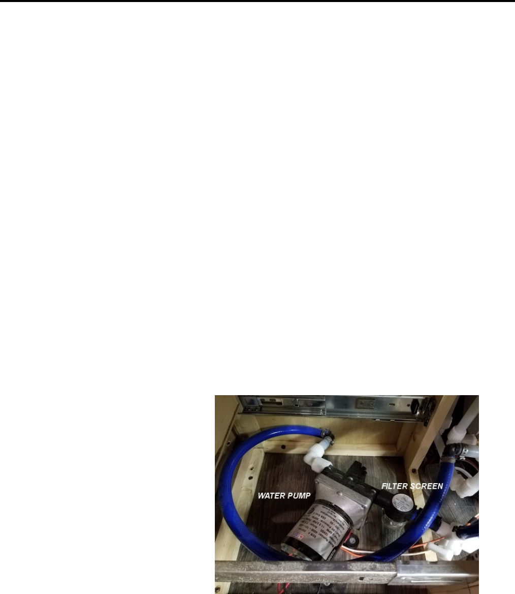
53
Plumbing Systems
To drain the water lines;
1. Turn off water pump.
2. Open all hot and cold low point drains.
3. Turn on all faucets.
For more complete direction on water system draining, refer to the 'Winterization' section in the
'Storage and Winterization' chapter.
Water Pump
The On-Board Fresh Water System requires a 12 volt water pump for operation. The water pump
provides water pressure at each fixture while dry-camping without a pressurized city/park water
connection. It is also used during the winterization procedure for pumping RV anti-freeze into the water
lines to prevent freeze-up. This procedure is outlined in detail in the 'Winterization' section in the
'Storage and Winterization' chapter.
The water pump is self-priming and operates automatically when its switch is in the on position and a
faucet has been opened. When the water pump senses a pressure drop in the system it will begin to pump
water to maintain that pressure. Each first use after water lines have been drained, the water pump will
run continuously for a minute or so until the water lines are primed and fully pressurized. Additionally
when a faucet is opened it may sputter for a few seconds until all air is purged from the water line and
faucet.
The power switch for your water pump will be located on the systems monitor/control panel typically
found in a galley overhead cabinet. The water pump is typically located inside the base of the galley
cabinet behind a drawer or access panel.
Shown at the right is an example
of a water pump. On the right side
you will see the filter screen
identified. The pump assembly is
typically located beneath a drawer
in a galley cabinet. It may also be
accessible from a removable
panel on the side of the cabinet.
On fifth wheel models the water
pump is typically located behind
the rear bulkhead in the pass-thru
storage compartment, accessed
from a service door.

54
Plumbing Systems
Water Pump Screen
Your water pump includes a serviceable filter screen that can be removed and flushed out if it becomes
clogged with debris. Note: This is merely a particle filter screen and does not provide water
purification.
The filter screen housing is located on the inlet side of the water pump and is made of clear plastic so
that you may perform a visual check of its condition without disassembly. It is recommended to inspect
the filter screen after running the first full tank of water. Clean and inspect monthly thereafter.
To remove filter screen for cleaning;
It is recommended that this procedure be performed at a time when the fresh water tank and water lines
have been drained to minimize water spillage onto the floor.
1. Turn off water pump.
2. Place a shallow drip pan or rag under the filter housing.
3. Unscrew the clear inspection housing cover and remover filter screen.
4. Flush out debris from filter screen and clear housing cover.
5. Reverse procedure to install.
6. Operate water pump to verify that there are no water leaks.
Additional information regarding water pump operation and maintenance can be found in your owner
information packet provided with your RV.
Showers and Faucets
Interior and exterior showers and faucets operate much like that of the type in your home. Keep in mind
that if you are dry camping with no city or park water connection you must have the water pump
switched on. For hot water at showers and faucets, the water heater will require sufficient time to heat
the water. For your safety, the interior and exterior shower faucets are equipped with a vacuum breaker
device. This device is designed to prevent backflow of potentially contaminated water into the fresh
water system. When the faucet is in the OFF position after use, water will drain from the shower head
and hose. This is not a defect or leak, but indicates that the faucet is working properly.
Water Heater
Your RV is equipped with either a 6 or 10 gallon water heater depending on model and available space.
Specific details are outlined in the 'Appliances and Equipment' chapter of this manual.
Turn water pump or master 12V disconnect switch off before
traveling. Road vibration could cause a faucet to open. If the water
pump is on, your fresh water supply could be pumped into the waste
holding tanks.

55
Plumbing Systems
Water Heater By-Pass
The water heater by-pass allows for winterization of the water system without filling the water heater
tank full of anti-freeze. The by-pass valve is located on the back of the water heater (see illustrations
below). Most water heater by-pass valves are accessible behind a removable cabinet panel or cabinet
drawer. The easiest way to find the by-pass valve is to locate the water heater on the exterior of the RV
then go into the RV and look at the cabinetry in that general location for a removable access panel or
bank of drawers that can be removed. Fifth wheel models are remotely located away from the water
heater in the exterior water center compartment on the driver side of your RV. Identified in RED
lettering its instructions are self-explanatory. Your RV dealer can assist you in finding and operating this
feature if necessary.
While the by-pass valve is oriented in the 'normal flow' position, water will travel into the valve
assembly and be redirected into the bottom of the water heater. With the water heater turned on, water
will then become heated inside its tank, then travel out the top of the water heater into the hot water lines
as demand requires.
With the valve oriented in the 'by-pass mode' position, water will flow through the by-pass valve and
back in to the hot water lines thus 'by-passing' the water heater tank. In this mode during the
winterization operation, anti-freeze is not allowed into the water heater tank.
Valve handles rotate 90 degrees clockwise to close and counter-clockwise to drain. Your valve handles
may not be oriented as shown however still function as outlined.
The water heater has a one-way check valve at the upper connection that prevents 'by-passed' water from
entering into the top of the water heater and therefore forces it into the hot water line.
This view illustrates the by-pass valve
oriented in the 'normal flow' position. To 'by-
pass', turn counter-clockwise 90 degrees.
This view illustrates the by-pass valve
oriented in the 'by-pass mode' position. To
switch to 'normal', turn clockwise 90 degrees.

56
Plumbing Systems
SANITIZING THE FRESH WATER SYSTEM
To ensure complete disinfection of the potable water system, it is recommended that the following
procedures be followed on a new system, one that has not been used for a period of time, or one that
could have become contaminated. This procedure is also recommended before long periods of storage
such as over winter.
To sanitize your fresh water system, follow this procedure:
1. Drain water lines, fresh water tank and water heater. Close all valves and replace water heater
anode/drain plug when complete. Set water heater by-pass valve to the 'normal flow' position to
allow sanitization of the hot water tank and by-pass valve assembly. If you have installed a water
filtration system, its filter can be removed at this time.
2. Prepare a chlorine solution using 1 gal. (3.8 L) of water and 1/4 cup (60 ml) household bleach
(sodium hypochlorite solution). With tank empty, pour chlorine solution into the tank. Use 1 gal
(3.8 L) solution for each 15 gal. (57 L) of tank capacity. This procedure will result in a residual
chlorine concentration of 50 ppm in the water system. If a shorter time period is desired, create a
solution of 100 ppm by using 1/2 cup of household bleach with 1 gal. of water.
3. Complete filling the tank with potable water. Turn on water pump. Open each faucet and run
water until a distinct odor of chlorine can be detected in the water discharged. Do not forget the
hot water taps, showers, and toilet.
4. Allow the system to stand for at least 4 hours when disinfecting with 50 ppm residual chlorine. If
a shorter time period is desired, a 100 ppm chlorine concentration should be permitted to stand in
the system for at least 1 hour.
5. Drain the entire system including hot water heater tank, fresh water tank, and water lines. Close
all drain valves and replace anode/drain plug in water heater.
6. Flush the system with fresh water as described in step #3 (omitting the chlorine solution). Repeat
as necessary until the smell of chlorine is gone. If you have installed a water filtration system, its
filter can be replaced at this time.
7. When flushing is complete, close all drain valves, replace anode/drain plug in water heater and
don't forget to drain gray and black holding tanks if you used them to contain the flushing water.
The system is now ready for use.
WASTE WATER SYSTEM
The waste water system in your RV is essentially two separate systems. A gray water system that
consists of the drain lines and holding tank for waste water from the sinks and shower or tub and a black
water system which includes the drain line and holding tank for toilet waste.
Do not turn on the water heater with the by-pass valve in 'by-pass
mode' without water in the water heater tank. Damage to the water
heater and heating element may occur if the water heater is turned
on without water in its tank. This type of damage is not covered
under warranty.

57
Plumbing Systems
The drain plumbing system is very similar to that used in your home. The sinks and showers or tubs
have water traps and are vented to the exterior to minimize waste gases from backing up into the RV.
The components are made of ABS plastics the same as plumbing parts found in modern homes, and are
just as durable and resistant to most chemicals and cleaners used in the household.
Each system is self-contained and allows for disposal of waste water at designated dump stations at your
convenience. A flexible sewer hose is required to connect the holding tank outlet to the inlet of an
approved waste water dump station or sewer system. This hose can typically be purchased at your local
department store or RV dealership. A storage location is provided for the sewer hose in the rear bumper
by removing the rubber cap at either end.
If you encounter a clogged sink, shower or tub drain, you will be able to disassemble the water trap
(sometimes called P-trap) in the same way that you would at home. Some models have a clean-out
access fitting for using a plumber snake tool. These fittings are generally located behind drawers at
galley cabinets.
Toilet
Your RV is equipped with a marine-type toilet. It is different than your toilet at home in that it does not
have a water tank attached to the back of it to flush waste out through the pipes. Your RV toilet dumps
waste directly into the black holding tank with very minimal pipe connecting between the two. By this
design the RV toilet requires very little water to flush and relies on gravity to do the dirty work.
This toilet operates by use of a foot pedal that is pressed downward to control function. The pedal has
two positions. To add water to bowl, press down half way. To flush, press all the way down. It is
recommended to keep a small amount of water in the bowl at all times except when traveling. You may
find that you will require more water in the bowl when flushing solids. Hold the flush pedal down long
enough to release the contents of the bowl, but not longer than necessary as this will result in excessive
water usage.
Unnecessary, frequent flushing of the toilet will quickly deplete your fresh water supply and fill your
holding tank faster. If the black water tank becomes full, you will no longer be able to flush the toilet
until the black tank can be drained. Remember to occasionally monitor tank levels.
Holding Tanks
Your RV will have a minimum of two holding tanks, a Black tank for the toilet and a Gray tank for the
sinks and shower or tub. Typically rear kitchen model RVs will have an additional gray tank for the
kitchen sink. Due to the distance of separation between kitchen and bathroom on rear kitchen model
RVs the drain lines cannot share the same gray tank and must be plumbed to each respective tank.
Unfortunately this means that the additional gray galley tank must be drained separately from the
primary waste outlet location.
The primary holding tanks are generally located beneath the bathroom with drain valve handles and
drain outlet(s) located on the driver side. On rear kitchen model RVs the additional gray tank is
generally located close to the kitchen area. Mid-profile fifth-wheel drain handles are located in the front
storage compartment. The black tank drain valve is identified with a black pull handle and the gray tank
drain valve is identified with a gray colored pull handle.

58
Plumbing Systems
The two or three tanks are not interconnected in any way other than the final drain connection and can
be drained individually through a common outlet.
In order to help prevent hard deposits from building up within the black tank and help to reduce
unwanted odors, it is recommended to always keep a small amount of water in the black tank. Generally
just enough to cover the bottom will do. This is easily done by filling the toilet bowl and dumping a few
times.
When using your RV drainage system and holding tanks it is recommended that the black holding tank
valve is kept closed until the tank is at least 3/4 full. If the black holding tank is allowed to constantly
drain with the valve open you may create a residue build up that will become difficult to flush out later.
Additionally, waste will build up along the internal edges of the drain valve potentially creating a
situation where the valve may not fully close which in-turn will cause a sewer leakage problem that may
not be resolved without disassembling the entire valve assembly. During self-containment use, the drain
valves and outlet should be securely closed and capped to prevent leakage of waste materials onto the
ground.
Do not put these items in toilet or drains:
Facial tissues, paper towels, sanitary products (including those labeled flushable),
wrappers, gum, cigarettes.
Detergents or bleach.
Automotive antifreeze, ammonia, alcohols, or acetones.
Grease from cooking, table scraps or other solids that may cause clogging.
Quick tips to keep your waste tanks flowing freely:
Keep black tank valve closed until tanks are at least 3/4 full before dumping.
Be sure to keep enough water in the black tank to cover the bottom to reduce sticking of
waste.
Use only RV specific toilet paper which is designed to decompose much faster than
household toilet papers.
Use only cleaners and deodorizing chemicals approved for use in RV holding tanks.
These chemicals are designed to aid in breaking down solid wastes and make the system
much more pleasant to use and clean.
Do not use harsh household drain cleaners.
Should you ever have a build up of solids, your RV is equipped with a Black Tank Flush System which
will likely clear this up. See section in this chapter titled 'Black Tank Flush System' for direction. If the
problem continues, it may be necessary to purchase a waste water digester from your local RV dealer
which can be added to the tank to help break down solids. Depending on the severity of the situation, it
may be necessary to repeat these procedures.
Draining Holding Tanks
Prior to draining your waste holding tanks it is recommended that you wear protective equipment such
as safety glasses or goggles, rubber gloves, and or face shield to prevent potential splashing of waste
water onto your mouth, nose and eyes.

59
Plumbing Systems
IMPORTANT:
Do not pull the holding tank drain valves open while the protective cap is attached to the drain
outlet.
Do not attempt to drain both waste holding tanks at the same time.
Always drain the waste holding tanks into an acceptable sewer inlet or dump station.
1. Remove sewer outlet cap by twisting cap counter-clockwise.
2. Locate and attach your sewer hose to the holding tank drain outlet by aligning outlet pins to hose
connector fitting and twisting clock-wise until secure.
3. Insert other end of the sewer hose into the sewer or dump station inlet, pushing it securely into
place. In some cases, adapters or elbows may be necessary or required at the dump station end of
the hose. Arrange the sewer hose so that it slopes evenly toward the dump station inlet.
4. Drain the black tank first. Before doing so, open the toilet ball valve with the foot pedal and
check to see that the tank is at least 3/4 full. You will gain additional flushing action by filling
the tank to at least 3/4 full with fresh water.
5. Firmly grasp the drain valve handle of the black tank (identified with a black handle) and pull the
valve fully open with a quick, steady pull.
6. Allow enough time for the tank to drain completely. Rinse and flush the tank through the toilet.
If additional flushing is necessary, this process can be repeated. Additionally you may use the
'Black Tank Flush System' at this time. See section in this chapter titled 'Black Tank Flush
System' for direction. When tank is empty and satisfactorily clean, push the handle in to fully
close the valve.
7. Drain the gray tank by pulling the gray colored handle. The gray tank is drained last to aid in
flushing the outlet and sewer hose. The gray water knife valve may be left open in a semi-
permanent hookup while connected to a RV park sewer connection.
8. Ensure that drain valves are closed. Remove the sewer hose from the RV drain outlet fitting and
cap the outlet.
9. Rinse out the sewer hose with fresh water and remove from the dump station connection. Sewer
hose may be stowed in bumper.
10. Replace sewer or dump station cap.
Blank Tank Flush System (San-T-Flush)
The black waste holding tank is equipped with a rinsing spray head that will aid in the removal of
sewage residue from the interior of the tank. This system uses a garden hose connection located along
the driver side or rear exterior wall of your RV. It appears similar to the city water inlet however will be
identified with the 'SAN-T-FLUSH' labeling. DO NOT mistake this connection for the city water inlet.
See additional literature in your owner information packet supplied with your RV.
Holding tanks are enclosed sewer systems and as such, must be
drained into an approved dump station. Both black and gray water
holding tanks must be drained and thoroughly rinsed regularly to
prevent accumulation of harmful or toxic materials.

60
Plumbing Systems
Odor Control
The secret to good air quality in and around your RV lies in finding an effective holding tank chemical
and applying the proper amount based on use and ambient temperature. It is important to note some
brands work more effectively than others. If you are experiencing unpleasant odors from your holding
tanks, try switching brands or adjusting usage before considering it a plumbing problem. Follow the
chemical manufacturer instructions for proper use.
The gray tank(s) can produce offending odors as well as the black tank and occasionally the rocking,
bouncing movement of the RV while driving may empty a drain trap of its water and allow odors to
enter the RV.
PLUMBING SYSTEMS AWARENESS
Plumbing system problems are typically of two categories: Inherent and neglect. Inherent problems are
generally the result of road vibrations and campground water pressure variations. Neglect problems
usually arise due to improper winterization, clogged filter screens, and not performing regular
maintenance checks. Most plumbing system problems can be avoided by conscientious maintenance.
Vibration, flexing and twisting while traveling can work pipe fittings loose. Check all plumbing for
leaks at least once a year. If the water pump runs when all faucets and drain valves are closed, you
should suspect a water leak. Leaks occur most often around threaded fittings. If necessary, clean and/or
tighten the fittings. Do not over tighten threaded fittings. Most only require little more than hand
tightening.
The use of a wrench on plumbing fixture water connections must be performed delicately as over
tightening may damage rubber seals, which in turn may create a leak. Fittings with rubber seals require
only a slight additional turn beyond hand-tightened. If you have a leak at a fixture, first attempt to hand
tighten the fitting. If that fails you may try a slight amount of tightening with a wrench, no more than 1/2
turn past hand-tightened. If a leak persists at the fitting, disconnect it completely and check for mineral
deposits or foreign matter at the seating surfaces. Clean the surfaces. Replace the seal if necessary and
tighten the fitting no more than 1/2 turn past hand-tightened.
Sewer drain cap must always be securely in place while the vehicle is
in motion. Local or state regulations may prohibit highway travel
unless the holding tank outlet is securely capped.
Do not leave the RV unattended during the tank flushing process.
Make sure the black tank termination valve is open and your sewer
hose connected to an approved dump station. Overfilling the black
water tank will result in water overflowing into the interior of your
RV from the toilet and the resulting damage will not be covered
under warranty.
DO NOT connect city water pressure to black tank flush system
unless drain valves are open. May result in an unsanitary condition
leading to illness or personal injury.

61
Plumbing Systems
Most hose and tubing connections at fittings use a specialized clamp. In an emergency you may be able
to tighten up a fitting connection leak with a standard automotive worm gear hose clamp however you
will want to have it repaired with the proper clamp by your dealership at your earliest convenience.
Spare water line fitting seals and a few hose clamps would be a great addition to your RV tool box.
Drain trap slip-fittings, drain outlet knife valves, and the drain outlet cap seal are also areas that need to
be checked occasionally for leakage as well.
Leaks caused by freeze damage can usually be prevented by proper winterization of the systems. See the
'Storage and Winterization' chapter for proper winterization procedures. Freeze damage can be
extensive and may include a burst water tank, split water piping, damaged water pump, toilet, or water
heater.
Some models require the use of a 'waterless' drain trap due to space limitations. In the event that a drain
line equipped with a waterless trap becomes clogged you must remove this trap prior to using any
mechanical drain-cleaning device. The internal components of the waterless trap can be easily damaged
and will no longer function properly if a drain clean-out snake tool is used. Pictured below you will see
the differences between the two drain trap designs used.
A typical 'P' trap.
A 'Waterless' trap.

62
Electrical Systems
To provide you with the safest possible product the electrical systems in your RV have been designed
using materials and assembly methods that meet or exceed all applicable codes, regulations, and
standards in effect at the time that it was manufactured.
There are two basic electrical systems in your RV: 120 Volt AC, and 12 Volt DC. Each of these has
their own sub-systems as explained in the following sections.
120 VOLT AC SYSTEM
The 120 volt AC system provides electricity for appliances such as the air conditioner, microwave,
refrigerator, water heater, fireplace (if equipped) and the power converter as well as all 120 volt wall
outlets. For this system to function you must be plugged into 'shore power' at an appropriate electrical
outlet designed for your connection. Additionally if you have a generator of adequate size, you will be
able to power these appliances through the 120 volt system as well. Your RV is equipped with either a
30 Amp or 50 Amp Power Distribution Center and AC power cord. This system does not rely on RV
batteries to function.
30 Amp Power Service
30 amp service is the most common found in the RV industry and used widely in most campgrounds.
With this service you will be able to run all 120 volt appliances, however if your RV is equipped with a
fireplace and microwave they will be wall switched on the same circuit to alternate use between the two
due to the amount of power that those two appliances require. Wall switching hi-power demand
appliances on a shared circuit is a common method used to comply with electrical codes when the Power
Distribution Center does not have enough 'code allowed' breaker switches. With 30 amp service you will
have one Ground Fault Circuit Interrupter sharing between the bath, kitchen, and patio protected outlets
all on one circuit. Additionally your AC power cord will be '3-wire' which will only allow for
connecting to the proper 30 amp service. Below you will see pictures identifying a 30 amp power
distribution panel and its power cord connection. Refer to the AC power cord connection label for
proper power supply to the RV.
+

63
Electrical Systems
50 Amp Power Service
50 amp service provides for more electrical capacity and usage at one time than that of 30 amp service.
With this service you will be able to run all 120 volt appliances simultaneously without switching the
microwave and fireplace (if equipped). 50 amp service will also allow for a second air conditioner to be
installed in the bedroom and run at the same time as the primary air conditioner in the living room. You
will have two dedicated GFCI protected outlet circuits, one for bath and the other for kitchen thus
allowing for use of higher-demand countertop appliances without tripping circuit breakers. Additionally
your AC power cord will be '4-wire' which will only allow for connecting to the proper 50 amp service.
Below you will see pictures identifying a 50 amp power distribution panel and its power cord
connection. Refer to the AC power cord connection label for proper power supply to the RV.
The power system in your RV is only as good as the power supply feeding it. If the campground has
only 30 amp service available, an RV with a 50 amp panel will only be able to use up to 30 amps of
power. Some campgrounds have only 15 amp service available which is not adequate to properly run an
air conditioner or certain other appliances.
Power Distribution Center
The power distribution center in your RV is a self-contained unit which includes the AC breaker
switches on the left side, DC fuses on the right side and the power converter in the lower half. The AC
breakers function the same as those at home and will 'trip' if there is an overloaded or shorted circuit.
When your RV is connected to an AC power source using the 30 or 50 amp power cord, the power
converter will automatically convert 120 volt power into 12 volts to supply all low voltage circuits. The
power converter also provides three-stage charging modes to help maintain battery state of charge.
The converter will supply a small current to the battery even when it is fully charged. To prevent excess
battery acid loss, check the battery levels every 30 days while the converter is connected to 120 volt AC
power. Always refill batteries with distilled water. See 'Battery Charging' in this chapter.

64
Electrical Systems
The 12 volt DC circuits are protected by an ATC Type 257 fuse. If you are experiencing continuously
blown fuses, do not attempt to 'fix' the problem by installing a larger amperage fuse. Continuously
blowing fuses indicates that there is a shorted or grounded hot wire or overloaded circuit and must be
immediately corrected. Keep a few spare fuses of each size in your RV tool box for emergency only.
The 120 volt circuits are protected by a common type circuit breaker and can be replaced if one becomes
damaged or non-functioning. If you are experiencing continuously tripped breakers, do not attempt to
'fix' the problem by installing a larger amperage breaker. Continuously tripping breakers indicates that
there is an over-loaded circuit, or shorted or grounded hot wire and must be immediately corrected.
Overloaded circuits can occur in the RV the same as at home whereas if you operate too many high
demand appliances on the same circuit at the same time you may overload it causing a breaker to trip.
Please refer to the Operator Manual included in your owner information packet provided with your RV
for additional information.
AC Power Cord
Sometimes referred to as the 'shore power' cord, your RV is equipped with a heavy duty detachable
power cord to connect to an external 30 or 50 amp (depending on model) rated AC power service. The
cord and plug are a molded, weatherproof assembly. The cord provides a correct ground connection to
the site service. Do not alter or cut the cord in any way. Do not remove the ground pin from the plug, or
defeat the grounding circuit in the RV. Never plug the AC power cord into an ungrounded receptacle.
Before connecting to the electrical supply, check its supply rating. Be sure it matches the rating label at
the AC power cord inlet on your RV unless you intend to use a power cord adapter.
The detachable power cord connects to the RV power inlet with a twist-lock connector and locking ring.
When connecting the cord to your RV, be sure to align the pins correctly before twisting the connector
in place. The locking ring provides additional strain relief and a weather resistant seal.
Making the Connection
1. Be sure the site power source breakers are OFF.
2. If the site power source breakers are not accessible, turn OFF the main breakers inside the
RV.
3. Insert the female plug end of the RV cord into the power inlet on your RV (usually
located on the drivers' side or at the rear). Hand tighten locking ring.
4. Insert the male cord end into the site power source receptacle. Push the plug straight into
the receptacle until it seats completely.
5. Turn ON site power source breakers.
6. Turn ON RV main breakers.
7. Reverse procedure for disconnecting power cord.
8. Stow power cord before leaving.
D
o not install
f
uses or circuit breakers with ampera
g
e ratin
g
s
g
reater
than that specified on the device or circuit label. This could
potentially overheat the wiring and start a fire.

65
Electrical Systems
Adapters and Extension Cords
In certain circumstances electrical adapters can be used to make the shore line power connection when
necessary, however when using adapters your available AC power for the entire RV is reduced to the
rating of the adapter. For example an RV wired with 50 amp service panel will be reduced to 30 amp
service. An RV wired with a 30 amp service panel will be reduced to 20 or 15 amp service depending
upon what adapter you have chosen for the supply connection. Some adapters can be found at many
department stores however your RV dealership will be the best source for your needs. This is another
great idea for your RV toolbox.
If it is necessary to use an extension cord to reach an available power supply, the correct size (wire
gauge and length) extension cord must be used. The longer the extension length becomes the larger the
wire gauge must be. Alternatively you may be able to purchase pre-made power cords in longer lengths
with the proper plug ends for your RV.
It is not recommended to combine adapters and extension cords or multiple extension cords. Do not
remove the ground pin from any cord or adapter, or defeat the grounding circuit in the RV or at the
power source. Never use a two-conductor extension cord, or any cord that does not assure correct and
adequate ground continuity.
Ground Fault Circuit Interrupter (GFCI)
A Ground Fault Circuit Interrupter (GFCI), also called Ground Fault Interrupter (GFI) is a device that
shuts off an electric power circuit when it detects that current is flowing along an unintended path, such
as through water or a person. It is used to reduce the risk of electric shock. The GFCI device does not
prevent electric shock, nor does it protect a person who comes in contact with both 'hot' and 'neutral'
sides of the circuit. It does not protect against electrical overloads.
Your RV will be equipped with 1 or 2 GFCI outlets depending on whether you have 30 or 50 amp
service. 30 amp service models will have 1 located in the bathroom. It protects outlets in the bath,
kitchen and at the patio outlet all on one circuit. 50 amp service models will have 2 GFCI outlets on
individual circuits. One is located in the bath which protects the bath outlet and may include the exterior
patio outlet and the other is located in the kitchen to protect kitchen outlets and may also include the
exterior patio outlet. Both of these arrangements may have additionally protected GFCI outlets.
Test the GCFI function each month while operating on AC power.
To test the GFCI:
1. Press the TEST button on the GFCI outlet. The RESET button should pop out indicating that the
protected circuit has been disconnected.
2. If the RESET button does not pop out when the TEST button is pressed, ground fault protection
on the protected circuit has been lost. Do not use the outlet or other outlets on the same circuit.
Have the electrical system checked by your dealer or a qualified electrician. Do not use the
system until the problem has been corrected.
The use of incorrect size or length extension cords, adapters, and/or
reducers may increase the risk of fire, personal injury or property
damage and in doing so will not be covered under warranty.

66
Electrical Systems
3. Press the RESET button to reset the GFCI and restore power to the protected circuit. If the
RESET button does not stay to the 'in' position you may have a shorted circuit. Do not use the
outlet or other outlets on the same circuit. Have the electrical system checked by your dealer or a
qualified electrician. Do not use the system until the problem has been corrected.
Note:
If any of the kitchen, bath or exterior patio outlets do not work, check the GFCI device for a
tripped RESET button. Reset if necessary. If the GFCI continues to trip, have the RV electrical
system checked at an authorized Outdoors RV dealer or by a qualified electrician. The GFCI may
have reached the end of its life expectancy.
12 VOLT DC SYSTEM
Marker / Tail / Turn / Brake / Back-up Lighting
The marker and rear tail lighting system is independent of the Interior/Exterior 12 Volt DC System and
is controlled primarily by the tow vehicle via the 7-Way cable at the front of your RV.
7-Way Cable Connection
Most new tow vehicles come equipped (or optioned in) with towing in mind and will already have the 7-
way connection installed near the hitch location on your vehicle. In the event that your tow vehicle is not
equipped with this connection we provide diagrams below of how this connection should be made.
Exterior 12 volt functions on this connection include: marker lights, tail/turn/brake and back-up lights (if
equipped) as well as the RV brakes, battery charge line (12 volt power), and grounding between the tow
vehicle and RV. These circuits are typically protected by fusing on the tow vehicle fuse panel.
Additionally the 12 volt power and RV brake lines are fused where the 7-way cord enters the RV.

67
Electrical Systems
Certain model RVs may be equipped with reverse back-up lighting which will connect to the Center
Auxiliary #7 connection with a 14 gauge yellow wire. Disregard this connection if your RV is not
equipped with back-up lights. Be certain that your installation includes a charge line from the tow
vehicle alternator or battery with a battery isolator solenoid using a minimum 10 AWG stranded copper
wire (rated appropriately for under-hood temperatures) to the Battery Charge #4 connection. Install a 30
amp fuse on this charge line near the tow vehicle power source. This circuit will help to maintain the RV
battery charge and by utilizing the battery isolator you will not run the risk of any RV appliances or
equipment draining power from the tow vehicle battery while it is not running. If your tow vehicle is
already equipped with the proper 7-way electrical connection you may not need to wire a charge line
circuit however it would be a good idea to verify that this circuit is providing power from the tow
vehicle.
Interior/Exterior 12 Volt DC System
12 volt lighting, appliances and equipped items are powered and fused through the Power Distribution
Center independently of the Marker and Tail Lighting System. These items may include, and are not
limited to, interior lights, exterior utility lights, range hood, monitor panel, LPG detector, water pump,
furnace, refrigerator, vents, entertainment equipment, awning, USB charging ports, etc. These items can
function either from the RV batteries alone or through the Power Distribution Center when the RV is
plugged into 'shore power'.
Please refer to section 'Power Distribution Center' and the Distribution Center Operator Manual
included in your owner information packet provided with your RV for additional information.
Other high power demand 12 volt equipment may include items such as stabilizer jacks, landing gear,
water tank heater, slide-out control, and wireless remote, etc. These items are typically fused separately
from the Power Distribution Center at an access panel location just rear of the RV batteries under the
floor for conventional travel trailers and for fifth-wheel models you will find this fusing located behind
an access panel just inside the passenger side exterior storage compartment.
These fuses are a 'Type-2' re-settable breaker fuse and typically do not need to be replaced if tripped. For
these fuses to be reset you must disconnect the batteries from the RV. Find and fix the cause of the
breaker tripping before reconnecting the RV batteries.
Do not install fuses or breakers with amperage ratings greater than
that specified on the device or circuit label. This could potentially
overheat the wiring and start a fire.
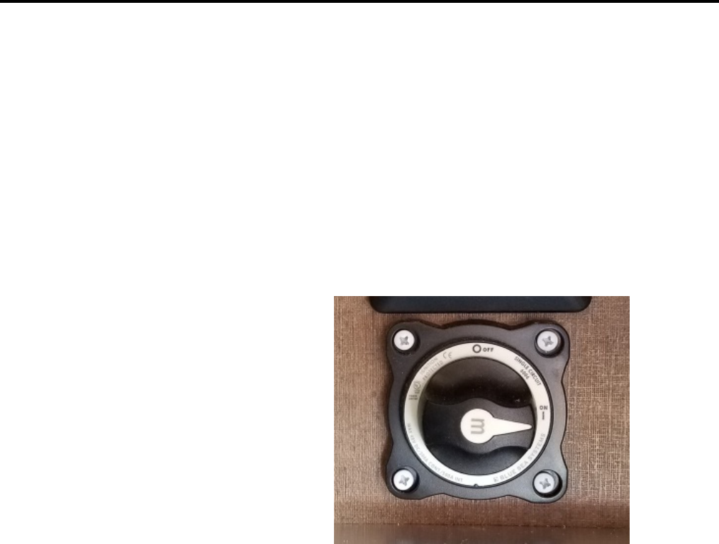
68
Electrical Systems
Battery Disconnect Switch
The battery disconnect switch allows for 12 volt power to be disconnected from the RV batteries. This
switch is located inside the exterior storage compartment on the passenger side behind an access panel in
the front wall (See picture below for identification). Fifth-wheel models will be located just inside the
passenger side exterior storage compartment on the forward wall.
The battery disconnect switch is typically used when your RV is put into either long term or short term
storage. Its purpose is to prevent the RV batteries from draining due to any 12 volt appliance or
equipment that requires a constant draw of power. It is recommended to turn the disconnect switch 'Off'
for any time that 12 volt power is not needed at the RV including during travel. Disconnecting 12 volt
power to your RV with the battery disconnect switch does not disable solar charging functions or
marker/tail light operations as wired from the factory.
THE RV BATTERY
The RV batteries are the heart of the 12 volt system. When your RV is not connected to shore power, or
if the generator (if equipped) is not running, most power needs are supplied by the batteries. If battery
voltages are low, many problems can occur. It is very important to maintain the batteries in a full state of
charge and to monitor their status regularly. The power converter charging and solar systems will help
you maintain your battery voltage capacity however when the RV is not connected to shore power or a
running generator, you must be energy efficient. Turn off any 12 volt lighting, appliances or equipment
not currently being used. Learn to conserve your battery power.
Low battery charge or bad batteries are a common cause of poor performance of slide-out rooms,
appliances and other components connected to the 12 volt system. Under low voltage, fuse and circuit
breakers can blow without a short circuit condition. The refrigerator control system requires at least 10.5
volts and will shut down even with propane supplied, potentially ruining food in the refrigerator. Low
voltage can also cause the furnace fan to run to slowly to operate an internal switch controlling the
furnace gas valve which will shut the furnace down. Avoid running the batteries down completely. The
breakaway switch emergency braking system relies on 12 volt power from your RV battery bank to
function properly.
Pictured at the right is the battery
disconnect switch shown in the
'On' position. In the on position
battery power will be supplied to
the 12 volt circuits of your RV.
Your switch may be either red or
black. There is no functional
difference between the two colors.

69
Electrical Systems
Battery Selection and Installation
Your RV has been designed to install up to two 12 volt Group 27 batteries (without box) or two 6 volt
GC2 batteries in the standard battery rack and up to four 6 volt GC2 batteries if your RV is equipped
with the expanded capacity battery tray. Or if you own a fifth-wheel model your battery rack will hold
up to four 12 volt Group 24 batteries or up to four 6 volt GC2 batteries. When selecting a 12 volt battery
always choose a RV/Marine grade deep-cycle battery. Your RV dealership or battery supplier can help
you with your choice of battery and the pro's and con's of each installation.
It is critical that your RV batteries are connected properly. Whether you have chosen multiple 6 volt
batteries or multiple 12 volt batteries they must be wired correctly or you may cause damage to the
batteries or internal wiring and fusing in your RV. Consult with your RV dealership or battery supplier
for proper wiring procedure.
Many RV'ers that 'dry camp' without shore power have had great success using multiple 6 volt batteries
rather than the typical 12 volt battery set-up. Multiple 6 volt batteries in conjunction with two or three
larger solar panels will generally provide a greater power reserve that is only limited by the amount of
direct sunlight available to recharge your batteries. Depending on your camping power consumption you
may find that this will satisfy your 12 volt power needs.
It is recommended that your batteries be secured in a battery box specifically designed for housing
batteries using an appropriate hold-down strap around the support frame of the RV. Check occasionally
to ensure that the straps have not worked loose.
Battery Charging and Maintenance
Under normal circumstances your RV batteries will maintain their charge by a combination of sources
including the tow vehicle charge line while on the road, while your RV is plugged into shore power and
with the solar panel(s) (if equipped). On those occasions when the battery needs to be charged from a
different source, please consult with your battery supplier for specific charging requirements for your
batteries.
Disconnect the 120 volt electrical cord and both cables from the RV
battery before working on either electrical system.
Remove rings, metal watchbands, and other metal jewelry before
working around the battery. Use caution when using metal tools. If
tools contact the battery terminals or metal connected to them a short
circuit could occur which could cause personal injury or fire.
Do not alloy battery acid to contact skin, eyes, fabrics, or painted
surfaces. The sulfuric acid in the battery could cause serious
personal injury or property damage. Wear eye protection when
working with batteries.
Never expose the battery to open flame or electric spark. Chemical
action in the battery generates hydrogen gas which is flammable and
explosive.

70
Electrical Systems
Battery Monitor
The battery charge level can be checked on the monitor panel.
1. Unplug the AC power cord to turn the power converter off.
2. Turn on a light or two to load the batteries slightly.
3. Press the 'Batt' switch on the monitor panel to activate the reading.
4. Read battery condition on the display.
Battery charge status will read L (Low 6 - 11.6 volts), F (Fair 11.6 - 12.1 volts), G (Good 12.1 - 12.7
volts), and C (Charge = 12.7 volts or greater).
SOLAR
Outdoors RV travel trailers and fifth wheels are equipped with different levels of solar capabilities. All
models include an exterior solar jack installed at the passenger side toward the front of the RV. Its
design is such that you may purchase a portable solar panel kit that may sit on the ground or table and
plug into the exterior jack. A portable solar panel system has its benefits in that you may be able to
follow the sun for maximum charging as opposed to roof-top panels that may become shaded throughout
the day. Portable panel units can be used in conjunction with roof-top installed panels for additional
battery charging. If you choose to add a portable solar panel to your charging system it is advised to
purchase a system that comes complete with a charge controller so that charging of the batteries can be
monitored and controlled.
All models come installed with a roof-top junction box which allows the consumer to add solar panels at
a later time. Your RV is pre-wired at this junction box for future roof-top panel installations. With this
junction box you may connect up to a total of three 170 watt panels (or equivalent total of 510 watts) by
simply plugging them in. If you choose to add roof-top panels to this junction box you will need to
install an appropriately rated charge controller to regulate battery charging if not already equipped. The
charge controller is wired in-line with the pre-wiring installed from the factory. Most models provide for
the charge controller to be installed in the bedroom front overhead cabinet and are labeled accordingly.
Pre-wire connections for the controller are located behind an access panel inside this front cabinet. Refer
to your charge controller installation instructions for specific wiring connections or contact your RV
dealership for more information.
Your RV may be optionally equipped with up to two large solar panels and a charge controller. This
configuration allows you to add one additional panel rated up to 170 watts to the roof-top, if space is
available, and plug in a portable unit at the exterior jack at the passenger side.
All solar system electrical connections are wired directly to your RV batteries. This provides for battery
charging while your RV is in storage with the 12 volt power supply shut off at the battery disconnect.
Solar panel maintenance is very minimal and really only requires keeping the panels clean to provide
optimal charging.

71
Electrical Systems
BULBS AND FUSES
When replacing light bulbs be sure to replace with the same wattage and base type as originally
equipped. Most typical bulbs have identifying numbers on them which you will need when shopping for
replacements. Many interior and exterior LED lights on your RV are non-serviceable. LED lights are
more durable and last many, many years in comparison to a typical incandescent bulb however in the
event that an LED light does burn out, the entire light fixture must be replaced. Please contact your
dealership or Outdoors RV for replacement.
The fuses in your RV power center are an automotive ATC type and can be found at any auto parts store
as well as most department stores. Blown fuses should always be replaced with the same size and rating
that was originally equipped. If you are unsure of the correct fuse size you will find that each 12 volt
circuit in the power panel is labeled with the correct fuse rating for each circuit.
It is recommended to keep a few replacement bulbs and fuses in your RV tool box.
Do not install 12 volt fuses or breakers with amperage ratings
greater than that specified on the device or circuit label. This could
potentially overheat the wiring and start a fire.

72
Propane System
Propane, also known as Liquid Petroleum Gas (LPG) is a clean burning dependable fuel for operating all
gas appliances when utilized properly. Propane is supplied from the LP tanks on the tongue of your RV
to operate your range, oven, furnace, and LP Gas generator (if equipped) and is an alternate energy
source for your refrigerator and water heater. The propane system components consist of two tanks with
shut-off valves, a regulator with auto-switchover, gas manifold and supply lines, and finally the
appliances. Propane is stored in the LP tanks as a liquid under high pressure and vaporizes into gas form
under the control of the pressure regulator. Consumption of propane gas depends upon the frequency
and duration of use of the propane appliances. The furnace, oven, and generator (if equipped) typically
have the highest consumption rates. During colder temperatures propane consumption will likely
increase due to increased use of the furnace and water heater. It is advisable to check the LP tanks often
and always keep one tank full.
PROPANE SAFETY
With proper handling precautions, propane is safe and provides modern convenience wherever you
travel however propane gas is highly flammable and is contained under high pressure. Improper use may
cause fire and/or explosions. Safety must be observed at all times when using the propane gas system.
Propane gas is colorless and odorless in its natural state. An odorant, similar to rotten egg smell has been
added for consumer safety purposes to help detect leaks and provide warning. A small amount of people
cannot smell this odor. If you are one of those people you must take extra care whenever you use your
RV. Keep the LP tank valves closed and turn off all appliances if the RV is not being used. If a sulfur or
'rotten egg' smell is detected in or around the RV or if the LP gas detector beeps perform the following
steps immediately:
IF YOU SMELL PROPANE
1. Extinguish any open flames and all smoking materials.
2. Shut off the propane supply at the container valve(s) or propane
supply connection.
3. Do not touch electrical switches.
4. Open doors and other ventilating openings.
5. Leave the area until the odor clears.
6. Have the propane system checked and leakage source corrected
before using again.
Ignition of flammable vapors could lead to a fire or explosion and
result in death or serious injury.

73
Propane System
Because of the potentially dangerous nature of propane gas the following warnings and advisories are
provided to ensure your safety. Please read and understand the importance of each.
Propane cylinders are equipped with safety devices that relieve
excessive pressure by discharging propane to the atmosphere.
Propane gas is highly flammable.
Propane regulators must always be installed with the regulator vent
facing downward and that regulators that are not in compartments
have been equipped with a protective cover. Owner must make sure
that the regulator vent faces downward and that the cover is kept in
place to minimize vent blockage that could result in excessive
propane pressure causing fire or explosion.
Portable fuel-burnin
g
equipment, includin
g
wood and charcoal
g
rills
and stoves, shall not be used inside the recreational vehicle because
the use of such equipment inside the recreational vehicle can cause
fires or asphyxiation.
Do not bring or store propane cylinders, gasoline, or other
flammable liquids inside the vehicle because a fire or explosion can
result.
This propane piping system is designed for use with propane only.
Do not connect natural gas to this system.
Securely cap inlet with the service valve closed when not connected
for use.
After turning on propane, except for normal cylinder replacement,
test propane piping and connections to appliances for leakage with
soapy water or bubble solution.
Do not use products that contain ammonia or chlorine to test for
leaks.
Can lead to a fire or explosion and result in death or serious injury.
Keep propane cylinder tanks away from heat sources.
Regularly inspect high pressure LP gas hoses for signs of cracks or
abrasion. Replace them before they become old enough to develop
leaks.
Never use a cylinder if it shows signs of dents, gouges, bulges, fire
damage, corrosion, leakage, excessive rust or other forms of external
damage.
Do not store LP tanks or use gasoline or other flammable vapors and
liquids in the vicinity of any appliances inside or outside of the RV.

74
Propane System
Propane System Advisory
Never check for leaks with an open flame. Use an approved leak detection solution or a non-
ammoniated, non-chlorinated soap solution only.
Always be careful when drilling holes or fastening objects to the trailer. The propane supply
lines could become punctured by a nail or screw.
Do not restrict access to propane containers. In an emergency, the container service valve must
be easily identified and accessible. The container compartment door must not have a locking
device and the propane label should be visible.
Do not use any propane container other than the one furnished with your RV without being sure
that all connecting components are compatible.
Turn off propane tank valves before entering a propane bulk plant or motor fuel station. Turn off
all pilot lights and appliances individually before refueling of motor fuel tanks and/or propane
containers. When not individually turned off, automatic ignition appliances may continue to
spark when propane is turned off at the container.
Do not use a wrench or pliers to close the cylinder shut-off valve. This valve is designed to be
closed by hand. If a tool is required, the valve needs repaired or replaced.
Be sure the cylinders are securely fastened in their rack whenever they are mounted on the RV.
If you do not have the special tools and training necessary, do not attempt to repair propane
system components.
DO NOT modify or alter the propane plumbing system.
If any appliance or piping has been serviced, ensure that a system leak check has been performed
by a trained technician. This should be verified before taking delivery of the RV.
SYSTEM COMPONENTS
LP Tanks
Also known as cylinders or bottles, modern LP tanks contain an Overfill Protection Device (OPD) that
prevents them from being filled past 80% of total capacity. This is a safety device that allows for vapor
expansion inside the tank without over pressurization. As a safety precaution, do not attempt to retrofit
your LP gas system with an older non-OPD tank. Do not use tools to tighten the LP tank shut-off
valve.
Hoses and Fittings
The LP gas hoses and fittings on your RV are essentially maintenance free however as precaution it is
advisable to inspect the rubber hoses at the LP tanks and from the regulator to the manifold for
deterioration or cracking whenever they are being disconnected and connected for filling. If you replace
any hoses, be sure that the replacements are the same size, and properly rated and approved for RV use
or contact your dealership for the correct part.
The green quick-disconnect fitting at each LP tank will be the one you will be operating most of the
time. This fitting is designed to be hand-tightened and loosened without the use of tools. To tighten, turn
clockwise. To loosen, turn counter-clockwise. This fitting has an internal O-ring seal and does not
require the use of any pipe sealants or thread tapes. If it ever leaks or cannot be hand tightened without
excessive force, the complete hose assembly must be replaced and its connections properly leak tested.
Do not use tools to tighten the green quick-disconnect tank fitting.

75
Propane System
Propane Regulator with Automatic Changeover
The regulator and auto-changeover (see picture below) is a unitized device located between the LP tanks
that control the flow of LP gas to the appliances. The auto-changeover will allow a continuous
uninterrupted flow of LP gas to the system. When the first tank is empty the auto-switchover will
automatically switch to the second tank without service interruption. The regulator receives hi-pressure
LP gas from the tanks and reduces it to a low pressure to be safely used with the RV appliances.
Automatic Changeover Operation
For operation of the LP system you will want to ensure that all appliances and pilot lights are off. With
both LP tanks filled and green quick-disconnect fittings hand tightened take notice of which direction
the tank indicator knob is pointing to. The tank that the indicator knob is pointing to will be the 'service'
tank and the other will be the 'reserve' tank. Fully open both LP tank valves. The indicator knob will
then become green meaning that the tank it is pointing to is fully pressurized or full. At this time you
may turn on any appliance gas valves and/or pilot lights and use as needed. When the service tank
becomes empty the auto-switchover will direct gas flow from the service tank to the reserve tank and the
indicator will turn from green to red. At this time you may refill the now empty tank before the reserve
tank becomes empty thus providing continuous service without interruption. When refilling the empty
tank, turn its supply valve fully closed then rotate the indicator knob to the reserve tank which will now
become the service tank. The indicator will change from red back to green. Disconnect, fill, and
reconnect the tank, open its valve and your auto-switchover is now ready to switch back to the original
tank when the now service tank becomes empty.
This system requires very little maintenance. The regulator however does have a vent at the backside
located under a white plastic cover. This vent must always face downward and be kept clear of
obstructions such as spider webs, etc. Periodically remove the cover to inspect that the vent is clear.
Remove any obstructions and reattach cover. Cover must remain on at all other times. Do not attempt to
relocate or mount the regulator differently than as it was assembled from the factory.
Do not attempt to adjust or repair the regulator. It is pre-set at the factory to certain specifications and
should only be adjusted by a qualified propane service technician. To avoid potential problems have
your LP gas system checked at least once a year by an authorized service center.
At the right you will see the regulator/auto-switchover
assembly installed between the LP tanks. Note that the
indicator knob, with its pointer to the left, indicates
that the tank on the left is the service tank. The green
indicator shows you that it is fully pressurized.

76
Propane System
Regulator Freeze-Up
Freezing and frosting of the propane regulator is quite common in extremely cold climates and usually
nothing to be concerned about provided everything is in working order and operating as it should. While
this 'freezing' of the regulator may be a symptom of an actual problem, it usually is a sign that outside
humidity is at a level capable of producing condensation. Occasionally however moisture can get into
the system and freeze up causing a blockage inside the passage of the regulator. Much of this moisture
intrusion is beyond your control and is introduced at bulk propane facilities. You can minimize potential
moisture intrusion by keeping the service valve on the LP tank closed and capped when not in use.
Other Cold Weather Considerations
As outside temperatures drop, the BTU value of LP gas becomes less. The colder liquid LP gas in the
tanks requires heat from surrounding air to vaporize. This lowering of BTU value can significantly
affect the performance of the system. To help reduce this effect, keep your LP tanks as full as possible
during colder temperatures.
Propane Gas Supply Lines
The propane gas system supply lines consist of the primary gas manifold, which is an iron steel pipe
secured to the bottom of the chassis, and secondary lines consisting of copper tubing which transition
from the supply manifold to each appliance with brass flare fittings making the connections. If repairs
are needed to these lines or any component of the propane system, DO NOT attempt to repair yourself.
Immediately follow the steps outlined in the DANGER warning 'IF YOU SMELL PROPANE' in this
chapter. Contact your RV dealership or a qualified propane service technician for proper repairs.
Although the propane gas system in your RV has been thoroughly tested for leaks at the factory, the gas
system should be inspected and checked for leaks by an RV dealer or qualified propane service
technician at least once a year.
BBQ Bib
Exterior kitchen model travel trailers are equipped with two BBQ bibs located directly below the
exterior kitchen area stemming from the LP gas manifold. This bib provides a connection to use a
portable BBQ in addition to the exterior cook top. To utilize this feature you will need a low-pressure
propane BBQ that will function properly on the tank regulated RV gas system. Otherwise your BBQ
may have to be modified by removing its regulator and adapting its gas inlet with the proper fittings to
connect to the factory installed bib. Consult with your RV dealership for helpful tips on this.
Shown at the right you will see two BBQ bibs
located off of the LP gas manifold. One is for the
cook top at the exterior kitchen and the other is
available for your supplied BBQ. As you can see
these bibs have a shut-off valve. The bibs shown
have their valves in the 'flow' position. To disable
flow turn valve handle 90 degrees. Propane does not
begin to flow unless the hose connection is plugged
into the bib.

77
Propane System
FILLING PROPANE TANKS
Prior to filling your LP tanks, please read and observe the following safety precautions:
All new containers (and in some cases used containers) may contain moisture, air or other contaminants,
and it is essential that these be removed before filling the container and placing it into service. Air in a
container carries moisture, which can cause service problems and potential freeze-ups as discussed
earlier.
All pilot lights, appliances, and their igniters (see operating
instructions) shall be turned off before refueling of motor fuel
tanks and/or propane containers.
Can cause ignition of flammable vapors, which can lead to a fire or
explosion and result in death or serious injury.
Your RV has been equipped with propane containers that feature an
Overfill Protection Device (OPD). NFPA 58 (Propane Code) states
that these portable cylinders shall not be filled without this device.
Do not under any circumstances use an older non-OPD cylinder.
Inadvertently overfilling of the pre-OPD cylinders can result in
uncontrolled propane flow that in unvented surroundings can cause
fire and/or explosion.
When refilling an empty cylinder, position the tank selector knob
toward the full cylinder. Failure to do so will result in propane
escaping out of the high pressure hose through the excess flow check
valve.
Do not fill propane container(s) to more than 80 percent of capacity.
A properly filled container contains approximately 80 percent of its
volume as liquid propane.
Overfilling propane container(s) can result in uncontrolled propane
flow, which could lead to a fire or explosion and result in death or
serious injury.
Failure to comply could result in a fire or personal injury.
When using this outdoor cooking area, the vehicle must be level and
stabilized.
Do not violate manufacturers' instructions on required clearances
for cooking appliances during use.
Do not store cooking appliances until cool to the touch.
Can lead to a fire and explosion and result in death or serious injury.

78
Propane System
It is recommended that your new LP tanks be purged at their first filling. If a container is suspected of
being depressurized or open to the atmosphere for a period of time it should be re-purged as if it were a
new container. Your LP filling station should be versed at this procedure.
To fill the LP tanks they must be removed from the RV and taken to a propane supplier or filling station.
Only qualified persons should fill your LP tanks. Do not attempt to fill them yourself.
1. Remove the propane tank cover.
2. Close the supply valve on the empty tank. Switch the tank selector knob on the auto-switchover
to the full tank.
3. Disconnect the green quick-disconnect fitting from the tank service valve. Turn counter-
clockwise to loosen. No tools should be required for this operation.
4. Be sure the plastic protective cap is clean and install it over the tank valve outlet. This will help
protect the valve fitting threads and will prevent contamination or debris from entering the valve
during transportation to a propane service facility.
5. Loosen the wing nut on the threaded rod. It should be loosened just enough to allow the hold
down bracket to clear the empty tank.
6. Remove the empty tank and have it filled. (Do not move the RV with the empty tank removed
and the hold down bracket loose).
7. Reverse the procedure to replace tank.
PROPANE SYSTEM CHECKS
Do a visual check of all exposed hoses, piping and fittings after you have arrived at a destination
and before you use the propane system.
Keep the tank valve closed and all gas appliances turned off if the RV is not in use.
Always have the system checked by a professional any time you detect a garlic/rotten egg like
odor or hear a sustained 'hiss' when you turn on the propane supply valves or the LP leak
detector alarm sounds.
PROPANE LEAK DETECTOR
A permanently installed propane leak detector alarm is included with your RV. It is located low to the
ground and typically mounted to kitchen or surrounding cabinets. The device contains an alarm that will
sound alerting you to the presence of low levels of potentially dangerous propane gas that may have
accumulated. It also requires frequent testing to ensure proper function. Please refer to the complete
operating instruction manual provided with your owner information packet.
Never check for leaks with an open flame.
Do not check copper and brass plumbing lines and fittings for leaks
using ammoniated or chlorinated household type detergents. These
chemicals can cause cracks to form on copper and brass.
If the leak cannot be located, take your RV to a propane service
representative.

79
Propane System
Activation of this device indicates the presence of LP gas, which can
cause an explosion and/or fire. This normally indicates a leak in the
LP gas piping or an LP gas appliance.
Test Detector operation after vehicle has been in storage, before
each trip, and at least once per month during use.
This detector will only indicate the presence of LP gas at the sensor.
LP gas may be present in other areas.
The detector is not suitable as a smoke or fire detector.
The detector is powered by a 12 volt source. Any interruption in
power will render this alarm inoperative. Always ensure power is
supplied especially when appliances are in use.
This device detects the presence of LP gas. IT DOES NOT
DISCONNECT THE GAS SUPPLY.
The Propane Leak Detector Alarm draws enough current to
discharge your batteries. Remember to turn the battery disconnect
switch to the 'off' position or disconnect the batteries during storage.
DO NOT attempt to repair the detector. If it fails to work properly as
outlined in its operation manual replace the entire unit.
The alarm may sound at times when no LP gas is present due to
household product use such as aerosol hairspray, certain cleaners,
adhesives, alcohol, etc.
IF THE ALARM SOUNDS...
1. Extinguish any open flames and all smoking materials.
2. Shut off the propane supply at the container valve(s) or propane
supply connection.
3. Do not touch electrical switches.
4. Open doors and other ventilating openings.
5. Leave the area until the odor clears.
6. Have the propane system checked and leakage source corrected
before using again.
Ignition of flammable vapors could lead to a fire or explosion and result
in death or serious injury.

80
Propane System
LIGHTING PROPANE APPLIANCES
Detailed operating instruction manuals for propane appliances are included in your owner information
packet. Please read these manuals for specific operating instructions. Always follow the appliance
manufacturer's lighting, operating and maintenance instructions.
Air trapped in the propane lines may delay the initial lighting of any appliance. It could take several
seconds or minutes for the propane to reach the appliance. This situation may potentially occur at
anytime the LP tanks are removed for refilling.
To purge trapped air from the propane system;
1. Verify that the valves on your LP tanks are fully open with the tank selector knob pointing to a
tank containing propane (identified by the green indicator).
2. Light a stovetop burner first.
3. When the stovetop burner flame burns steadily, your gas lines are now purged of any trapped air.
4. Turn off the stovetop burner.
5. Light any appliance as required.
The first time the furnace or oven is operated paints and oils used in manufacture may generate some
smoke and fumes. If this occurs, open doors and windows to air out the RV. These materials should burn
off after the first 15 to 20 minutes of appliance operation. During this 'burn-off' period your LP gas
detector, smoke and CO detectors may alarm. You can temporarily remove the batteries from smoke and
CO detectors to avoid this annoyance however do not attempt to disable the LP gas detector at any time.

81
Appliances and Equipment
NOTE: In this chapter we rely on the component manufacturer manuals that have been supplied with
your RV in the owner information packet. We will only provide summary information for each
component. For detailed information, please read and understand each component's operation manual
and literature. In the event that your appliance operation manual is missing, you may download it from
the manufacturers' website or contact Outdoors RV or your RV dealership.
~ Please read and understand the following safety warnings prior to operating any LP gas cooking
appliance.
Never attempt to repair or alter a gas or electric appliance or
component. Always consult an authorized and qualified service
agency or technician.
Do not use gas cooking appliances for comfort heating.
Can lead to carbon monoxide poisoning, which can lead to death or
serious injury.
Gas cooking appliances need fresh air for safe operation.
Before operating:
Open vents or windows slightly or turn on exhaust fan prior to using
cooking appliance.
Gas flames consume oxygen, which should be replaced to ensure
proper combustion.
Improper use can result in death or serious injury.
Do not operate this appliance unless the privacy curtain (if
equipped) is secured away from the appliance or removed.
Can cause a fire which could result in death or serious injury.
WHAT TO DO IF YOU SMELL GAS
Do not try to light any appliance. Extinguish any open flame
including cigarettes.
Evacuate all persons from the vehicle.
Do not start the vehicles engine or electric generator (if equipped).
Do not touch any electrical switch (including lights) or use any
phone or radio in the vehicle.
Shut off the gas supply at the gas container (bottle) or source.
Immediately call your gas supplier from a neighbors phone. Follow
your gas suppliers instructions.
If you cannot reach your gas supplier, call the fire department.
Do not turn on the gas supply until the gas leak(s) have been
repaired.

82
Appliances and Equipment
FURNACE
The furnace installed in your RV is an LP gas appliance. Carefully read the manufacturer's user manual
for complete operational and safety instructions provided in your owner information packet prior to
using the furnace.
The furnace utilizes a sealed combustion system, which means the combustion chamber is completely
sealed from the inner atmosphere of your RV. Combustion air is drawn in from the outside and
combustion by-products are expelled outside through an exhaust vent.
New furnaces sometimes emit smoke and an odor during the first 5-10 minutes of initial use due to paint
and oils burning off the heating chamber. Do not mistake this for a malfunctioning furnace. Opening the
windows and doors prior to first use will help reduce smoke and odors.
Before operating the furnace check the location of the exhaust vent on the exterior of the RV to be sure
it will not be blocked by the opening of any door or exterior items such as a bush, tree or patio furniture.
Exhaust heat can be hot and can potentially cause damage or start a fire to items sitting against the
exhaust vent outlet.
If this appliance fails to light after refilling the LP tanks or opening the LP gas system you may have
trapped air in the propane lines. Refer to the section 'Lighting Propane Appliances' in the 'Propane
System' chapter for lighting procedure.
WATER HEATER
Your water heater is a combination LP gas/120V electric appliance that can be operated in either mode
depending on your camping environment. It is protected at the power distribution center by a 15 amp re-
settable household type breaker. Carefully read the manufacturer's user manual for complete operational
and safety instructions provided in your owner information packet prior to using your water heater.
Hot water heaters require very little care. However, the most common cause of problem with the water
heater is turning it on before its tank is filled with water. Even running it for a brief period of time
without water will damage the electric heating element.
Prior to operating your water heater for the first time, be sure there is water in its tank. The water heater
by-pass must be in normal flow mode to allow water into the tank. Next connect the RV to a water
source or if using the on-board water system ensure that the water pump is turned on. Open a hot water
faucet until water is flowing with no air in the line. When water is flowing from the faucet, the water
heater tank is full and is now safe to turn on.
If this appliance fails to light after refilling the LP tanks or opening the LP gas system you may have
trapped air in the propane lines. Refer to the section 'Lighting Propane Appliances' in the 'Propane
System' chapter for lighting procedure.
Refer to chapter 'Storage & Winterization' for proper freeze protection procedures through winter
months and when not in use for periods of time.

83
Appliances and Equipment
WATER PUMP
Carefully read the manufacturer's literature for complete operational instructions provided in your owner
information packet prior to using your water pump. Refer to section 'Water Pump' in the 'Plumbing
Systems' chapter of this manual for basic operation.
REFRIGERATOR
Your refrigerator is a 2-way combination LP gas/120V electric appliance that can be operated in either
mode depending on your camping environment. Carefully read the manufacturer's manual for complete
operational and safety instructions provided in your owner information packet prior to using your
refrigerator.
If this appliance fails to light after refilling the LP tanks or opening the LP gas system you may have
trapped air in the propane lines. Refer to the section 'Lighting Propane Appliances' in the 'Propane
System' chapter for lighting procedure.
RANGE / OVEN / COOKTOP
This cooking appliance installed in your RV operates solely on LP gas. Carefully read the
manufacturer's user manual for complete operational and safety instructions provided in your owner
information packet prior to using.
RANGE HOOD
The range hood operates on 12V power and should be used for ventilating when cooking, especially
when boiling water or cooking that gives off high moisture content. Prior to operating, verify that the
exterior vent flap is unlatched and opens freely.
Periodically clean any cooking grease and splatters from the fan screen and underneath the range hood
to reduce the risk of fire hazard and flame spread. Do not use harsh chemical cleaners or abrasives.
Warm soapy water is recommended.
MICROWAVE / CONVECTION OVEN
Your microwave or convection oven (if equipped) is powered by 120V through the power distribution
center. It is fused by a 15 amp re-settable household type breaker. Carefully read the manufacturer's user
manual for complete operational and safety instructions provided in your owner information packet prior
to using.
Never operate the microwave oven while it is empty or with any metallic object inside. This may cause
unwarrantable damage to the appliance.
If your RV is equipped with an electric fireplace and 30 amp service, the microwave and fireplace will
be switched so that only one or the other appliance can be operated at one time. You will generally find
this switch located on the wall near the living room TV. To use the microwave the switch must be in the
'Microwave' position.

84
Appliances and Equipment
FIREPLACE (If Equipped)
Your fireplace (if equipped) is powered by 120V through the power distribution center. It is fused by a
15 amp re-settable household type breaker. Carefully read the manufacturer's user manual for complete
operational and safety instructions provided in your owner information packet prior to using.
If your RV is equipped with an electric fireplace and 30 amp service, the microwave and fireplace will
be switched so that only one or the other appliance can be operated at one time. You will generally find
this switch located on the wall near the living room TV. To use the fireplace the switch must be in the
'Fireplace' position.
AIR CONDITIONER
Your air conditioner is powered by 120V through the power distribution center. It is fused by a 20 amp
re-settable household type breaker. Carefully read the manufacturer's user manual for complete
operational and safety instructions provided in your owner information packet prior to using.
As a general rule, your air conditioner will cool down the room air by about 15-20 degrees, depending
on the outside temperature and humidity conditions.
To maintain peak operation of your A/C, periodically clean the foam filters located just inside the access
covers of the return air grille. They can be soaked in mild soap and water, gently rinse clean. Do not use
harsh chemicals or cleaners.
You can effectively increase your A/Cs efficiency by following a few simple steps whenever possible:
Park in shaded areas.
Keep blinds and shades pulled down.
Keep windows and doors shut and minimize their usage.
Operating on High Fan/Cooling mode will provide the maximum efficiency in high humidity or
high temperatures.
Use awnings to block direct sunlight exposure on the RV.
Avoid using heat producing appliances.
Give the A/C a 'head start' by turning the A/C on earlier in the morning.
If your RV has 50 amp electrical service the bedroom roof vent is pre-wired inside the ceiling for an
A/C. Your dealership can provide this installation for you.
This heater is hot when in use. To avoid burns, do not let bare skin
touch the hot surfaces. The trim around the heater outlet becomes
hot during operation.
High temperatures may be generated under certain abnormal
conditions. Do not partially or fully cover or obstruct the front of
this heater.

85
Appliances and Equipment
THERMOSTAT
The thermostat in your RV controls functions of both the furnace and air conditioner. Carefully read the
manufacturer's literature for complete operating instructions provided in your owner information packet
prior to using.
TV / STEREO ANTENNA
The TV antenna on your RV is a combined unit that provides signal for both the TV and stereo. To
maximize the antenna signal to your TV you must switch 'on' the power button on the wall plate behind
your TV. The red LED will be lit when functioning. See 'Figure 1 - Living Room Configuration'
diagram on the following page.
Carefully read the manufacturer's literature for complete operating instructions provided in your owner
information packet prior to using.
TV / SATELLITE CONNECTIONS
Your RV is wired to provide you with TV and/or satellite broadcasting in both the living room and
bedroom (satellite connectivity in bedroom not available on all models). You can receive VHF/UHF,
AM/FM and satellite signal with the installed wiring and connections.
Carefully read the manufacturer's literature for complete operating instructions provided in your owner
information packet prior to using.
Your viewing options include signal from the roof top TV antenna, signal from campground coax cable,
or signal from your purchased satellite dish and receiver.
There are a few combinations of signal viewing options available to you based on the wiring as installed.
They are as follows:
You can view cable coax signal at both living room and bedroom TV location simultaneously.
However you cannot view cable coax signal at the same time as over-the-air antenna signal.
You can view over-the-air VHF/UHF antenna signal at both living room and bedroom TV
locations simultaneously. However you cannot view antenna signal at the same time as cable
coax signal.
You can view satellite signal (via your purchased satellite dish and receiver) to either the living
room or bedroom (if equipped) locations or both simultaneously, however both locations
simultaneously will be required to view the same programming.
You can view satellite signal in one room and cable or antenna signal in the other simultaneously
if you are properly equipped with satellite dish and receiver.
Your choice of viewing may require additional coax jumper cables to connect from TV and satellite
receiver to appropriate wall jack connections as well as for diverting satellite signal from the living room
location to the bedroom location.

86
Appliances and Equipment
The following diagrams identify the necessary connections for each viewing option.
FIGURE 1
LIVING ROOM CONFIGURATION
These wall plates are typically located
behind or above your living room TV.
This connection is
used to rout a
satellite signal from
the 'Satellite'
connection on the
wall plate at the left
into the bedroom or
aux TV 'DSS'
location. This will
require a short coax
jumper lead
connecting the two
terminals. (Not all
models are
equipped with this
feature).
This connection is
for a cable or
antenna signal. For
a cable signal the
switch at the right
will be in the 'off'
position. For an
antenna signal the
switch must be in
the 'on' position
with the red light
lit up.
This connection
provides the
satellite signal
from the exterior
'DSS' connection
and will connect
to your receiver
box. You may
also 'jumper' this
connection to the
bedroom location.
FIGURE 2
BEDROOM OR AUX TV LOCATION
CONFIGURATION
These wall plates are typically located in the wall or
ceiling near your bedroom or auxiliary TV location.
Not available on all models.
This connection
provides satellite signal
when 'jumpered' from
the 'DSS' connection to
the 'Satellite' connection
at the living room
location. (Not all
models are equipped
with this feature).
This connection is
for a cable or
antenna signal. For
a cable signal the
switch at the wall
plate in the living
room will be in the
'off' position. For
an antenna signal
the switch must be
in the 'on' position
with the red light
lit.
This outlet provides
a power source for a
12V TV or can be
used to charge cell
phones or power
other accessories.

87
Appliances and Equipment
TELEVISIONS
Outdoors RV equips travel trailers with many different sizes and brands of television sets including
120V and 12V powered with internal DVD players. Please refer to the manufacturers manuals included
in your owner information packet for specific care and operating instructions.
AWNING (with LED light feature)
Your awning is 12V powered and switched at either the monitor panel or adjacent to the primary entry
door to provide operational viewing. Additionally if your RV is equipped with the wireless remote
function controller you may operate your awning from outside or inside the RV. When rain is expected,
it is recommended that you tilt the awning away from the entry door so that water can properly run off
and away. In the event that you have power failure to the awning, it may be retracted manually.
Carefully read the manufacturer's literature for complete operating instructions provided in your owner
information packet prior to using.
Your awning includes LED strip lighting in place of a conventional patio light. This feature is typically
switched near the primary entry door next to other entry light switches.
FIGURE 3
EXTERIOR CONNECTIONS
(These connections are typically located on
the driver side or rear of your RV)
This connection
provides satellite
signal to the wall
plate located at the
living room
location identified
as 'satellite' in
FIGURE 1.
(This is where you
will connect your
purchased satellite
dish).
This connection
provides cable
signal to the wall
plates at the living
room and bedroom
locations identified
as 'TV 1' in
FIGURE 1. (This is
where you will
connect the
campground TV
coax).
If heavy wind or rain is in the forecast, or whenever you leave your
RV for a period of time, it is best to retract the awning. Damage to
the awning or RV due to weather is not covered under the Outdoors
RV warranty or the awning manufacturer warranty.
Do not attempt to repair or modify the awning. The awning roller
tube is under extreme spring tension and if handled incorrectly
could cause serious bodily injury. Repairs should only be performed
by an authorized dealer or qualified technician.

88
Appliances and Equipment
SLIDE-OUT TOPPER
Your RV may be optionally equipped with slide-out room topper(s). Functioning similar to that of an
electric awning, their operation is fully automatic while the slide-out room is extended or retracted.
Before retracting the slide-out room, verify that no branches or debris have come between the topper and
the roof of the slide-out room. Damage may occur if debris is allowed to be rolled up into the topper
awning. Carefully read the manufacturer's literature for complete operating instructions provided in your
owner information packet prior to using.
POWER ROOF VENTS
Three variations of 12V power roof vents are installed in Outdoors RV travel trailers. Your model may
not include all variations. Currently offered are the Maxx-fan with remote (reversible fan), Maxx-fan
with wall switch (non-reversible fan), and the standard exhaust only fan. When operating any power
roof vent in exhaust mode you will find that it will function more efficiently if you slightly open a
window or two to allow a more circulating airflow. Open the roof vents when showering, bathing,
washing dishes, cooking on the stovetop, or anytime hot water is used. Opening these vents will allow
moisture to escape. Ventilation is extremely important in reducing the formation of condensation.
Carefully read the manufacturer's literature provided in your owner information packet for complete
operating instructions prior to using.
MANUAL ROOF VENT
Your RV may be equipped with manually opening roof vent(s). Open the roof vents when showering,
bathing, washing dishes, cooking on the stovetop, or anytime hot water is used. Opening these vents will
allow moisture to escape. Ventilation is extremely important in reducing the formation of condensation
and mildew. Remember to close these vents before traveling as they may get damaged by excessive
wind force at freeway speeds.
REAR MONITOR CAMERA
The optionally installed rear monitor camera provides additional safety measures while backing and
parking your RV. Its operation requires that your tow vehicle and RV have their parking lights turned
on. Carefully read the manufacturer's literature provided in your owner information packet for complete
operating instructions prior to using. (Not available on all models).
HEATED HOLDING TANKS
Your RV includes heated holding tanks. Your gray and black waste holding tanks are fully enclosed
insulated and duct heated whenever your furnace is operating.
The fresh water holding tank is also fully enclosed and insulated as well, however not all models are
heated in the same way. Your RV may include an optionally installed 12V heat pad attached to the
bottom of the fresh water tank. This heat pad will be in addition to ducted heat provided by the furnace
while it is operating. The power switch for this heat pad will be located near or on the systems monitor
panel. You will recognize it as being red and will illuminate when turned on.

89
Appliances and Equipment
To operate the fresh water tank heat pad;
1. When the outside temperature is near freezing, simply switch 'on' the holding tanks heater.
2. There must be liquid in the holding tank when the heater pad is turned on.
3. The tank heater immediately starts to protect your holding tank from freezing up.
4. The built-in sensor in the heat pad will turn on heating when temperatures are at 44º F or below.
When the water within the tank is heated and rises to 64º F, the tank heater will automatically
power cycle 'off' and deactivate.
5. Switch or power 'off' when outside temperatures are above freezing, or when tanks are empty.
6. Failure to follow these operating instructions could result in voiding your warranty.
MONITOR PANEL
Multiple styles of monitor panels are installed in Outdoors RV products. Some include very basic
functionality while others include additional equipment switching. They will all include holding tank
full capacities (fresh water, gray and black waste) and battery charge status.
To check tank levels or battery charge value, press and hold the appropriate button for the system you
wish to check. The panel indicator LEDs will light up to current levels.
Water and holding tanks monitor will read E (Empty), 1/3, 2/3, or F (Full). Keep in mind that you may
for example have a holding tank that reads 2/3 however it may be nearly to the Full (F) mark and not yet
indicate so.
Refer to the 'Battery Monitor' section in the 'Electrical Systems' chapter for specific procedure on
displaying correct battery charge value.
Erroneous Readings
The monitor panel displays readings from sensors located along the inner sides of the holding tanks.
These sensors can potentially send false readings under the following conditions:
Water with low mineral content. Minerals in water help conduct the electrical signal to the
monitor panel.
Contamination. Residue remaining on the inside of the gray and black tanks after dumping
(caused by normal use or putting grease, oils, etc. in the tanks).
Low battery voltage.
Loose wiring connections or bad grounding.
PROPANE LEAK DETECTOR
See 'Propane System' chapter for information and warnings regarding this device. Carefully read the
manufacturer's literature provided in your owner information packet for complete operating instructions
prior to using.
CARBON MONOXIDE DETECTOR (Battery and Hard-Wired)
Your RV is equipped with a carbon monoxide detector that detects the presence of deadly carbon
monoxide gas.

90
Appliances and Equipment
Carefully read the manufacturer's literature provided in your owner information packet for complete
operating instructions prior to using. Please read and understand the following safety warnings before
using your RV.
Test the CO alarm once a week. If the CO alarm ever fails to test correctly, have it replaced
immediately! If the CO alarm is not working properly it cannot alert you to a problem.
This CO alarm will eventually reach its end of life. See operating literature included with your owner
information packet for specific details regarding CO alarm end of life.
If the alarm sounds:
1. Immediately move to fresh air, outdoors, or by an open door or window. Do a head count to
check that all persons are accounted for. Do not re-enter the RV or move away from the open
door or window until the emergency services responder has arrived, the RV has been aired out,
and your CO alarm remains in its normal condition.
2. Call your emergency services, fire department, or 911.
This CO alarm will only indicate the presence of carbon monoxide
gas at the sensor. Carbon monoxide gas may be present in other
areas.
THIS IS NOT A SMOKE ALARM. This CO alarm is designed to
detect carbon monoxide from ANY source of combustion. It is NOT
designed to detect smoke, fire or any other gas.
The silence feature is for your convenience only and will not correct
a CO problem. Always check your RV for a potential problem after
any alarm. Failure to do so can result in injury or death.
Battery operated CO alarms do not operate without working
batteries. Removing the batteries, or failure to replace them at the
end of their service life, removes your protection.
Hard-Wired CO alarms do not operate if its circuits fusing is
removed or blown. Ensure that the CO alarm is functioning while
your RV is in use.
Actuation of your CO alarm indicates the presence of carbon
monoxide (CO) which can kill you. In other words, when your CO
alarm sounds, you must not ignore it.
Do not attempt to repair the CO alarm. If it becomes damaged or
inoperable it must be replaced immediately.

91
Appliances and Equipment
Some symptoms of CO poisoning;
Mild Exposure:
Headaches, running nose, sore eyes, often described as 'flu'-like symptoms.
Medium Exposure:
Dizziness, drowsiness, vomiting.
Extreme Exposure:
Unconsciousness, brain damage, death.
~ Check with a medical professional if you are experiencing any of these symptoms.
For your safety and to keep your carbon monoxide alarm in good working order, follow the tips below.
Verify the alarm, lights and battery operation by pushing the 'Test' button weekly.
Vacuum the CO alarm cover with a soft brush attachment once a month to remove accumulated
dust.
Instruct children to never play with the CO alarm. Warn children of the danger of carbon
monoxide poisoning.
Never use detergents or solvents to clean the carbon monoxide alarm.
Avoid spraying paint, hair spray, air fresheners, or other aerosols near the CO alarm.
Do not paint the CO alarm. Paint will seal the vents and interfere with the sensors ability to
detect CO.
Test the alarm operation after your RV has been in storage, before each trip and at least once a
week during your camping season.
SMOKE DETECTOR
Refer to chapter 'Living With Your RV' for reference.
WIRELESS FUNCTION CONTROLLER
Your RV may be equipped with a multi-function wireless controller. This feature allows for the remote
operation of many of the main components in your RV such as slide-out rooms, awning, power stabilizer
jacks, exterior lighting, etc. Carefully read the manufacturer's literature provided in your owner
information packet for complete operating instructions prior to using.
SPARE TIRE CARRIERS
Folding Bumper Mount
Conventional A-frame models are equipped with a folding bumper mount spare tire carrier. By
removing the locking pin the carrier may be lowered to allow access to any service compartment that
may be behind. Outdoors RV does not provide a specific wrench or socket for removing your spare tire
from its carrier.
When using the wireless remote for awning patio lighting the
manual wall switch must be left in the 'on' position for the remote to
operate the light properly. If the wall switch is left 'off', the remote
will appear to not function properly.

92
Appliances and Equipment
We advise you to purchase a wrench with an appropriately sized socket for spare tire removal prior to
hitting the road. Add this socket and/or wrench to your RV tool box.
Chassis Under-Mount
Fifth-wheel and ramp model RVs incorporate a spare tire mount located under the chassis just behind
the axles. Your fifth-wheel or ramp model RV is provided with a special wrench, typically located in the
front pass-thru storage compartment, for operating this tire carrier. You will find a hole in the side of
the skirt metal, usually on the passenger side behind the axles, used for access to the carrier drive
mechanism. This mechanism operates by rotating counter-clockwise to lower and clockwise to raise
much the same as the spare tire carrier on a pick-up truck. If you will not be returning the spare or flat
tire to the carrier, remember to raise the mechanism cable so that it does not get hung up on something
while traveling.
SLIDE-OUT ROOM
Outdoors RV utilizes two different style slide-out mechanisms (not all models have slide-out rooms).
One style is a 'Ram' system and consists of two ram mechanisms that are driven by a single 12V motor
with drive shafts on each side. This system is located within the chassis structure. The other is an 'In-
Wall' system that is mounted in the sidewall of the RV and is operated by two 12V motors at each upper
corner of the wall opening. Carefully read the manufacturer's literature provided in your owner
information packet for complete operating instructions prior to using.
Before operating the slide-out room, level and stabilize your RV. If the RV is not level, the slide-out
room and/or mechanism may become damaged over time. Stabilizer jacks help keep the RV square so
that the slide-out room extends, retracts and seals correctly. Be sure stabilizer jacks are placed on a solid
ground surface. Piers or supports are not necessary under the slide-out room when extended.
The slide-out mechanisms may occasionally make some amount of noise during operation. Some
amount of noise is normal especially during the break-in period while components are seating properly.
These noises will decrease after a period of time. Note that there will always be some noticeable noises
when operating the slide-out.
When the slide-out room is extended, outside elements such as rain, snow, ice, dirt and other debris may
cling to the outside surfaces of the slide-out room and mechanism. When the slide-out room is retracted,
whatever is on the exterior will be brought inside the RV. Before retracting the slide-out room, check the
outside surfaces. Wipe them dry or clean as much as possible. If the slide-out is extended for a long
period, be sure to check for insect nests, etc before retracting.
Stand clear of the slide-out rooms' path and verify that there are no
interior or exterior obstructions before extending or retracting the
slide-out. The underside of the slide-out has hard, sharp edges
protruding. Do not allow children under any slide-out rooms at any
time. Keep all people, pets and objects away from the slide-out room
and mechanism during operation. The mechanism may catch loose
clothing or pinch or crush appendages. Failure to follow these
warnings could result in serious injury or death.

93
Appliances and Equipment
Check for standing water or ice on the roof (if not equipped with slide topper). Remember that the slide-
out seals are not designed to remove all of the water or debris that may accumulate on the exterior
surfaces. You must wipe off as much as possible before retracting the slide-out room.
Slide-out Room Helpful Tips
The RV must have fully charged batteries especially when you are not plugged into shore power.
Turn off all unnecessary lights and 12 volt components prior to extending or retracting.
The RV must be level with stabilizer jacks extended.
Make sure the slide-out room has clearance, inside and outside to extend or retract.
Make sure water and debris are removed from the exterior and roof before retracting.
Avoid injury by keeping all body parts out of the way of the slide-out room.
Make sure all other people are clear of the slide-out room before extending or retracting.
DO NOT ride in the slide-out when extending or retracting.
DO NOT step on the slide-out floor, or use the dinette or sofa of the slide-out when the room is
retracted. The slide-out floor is not supported while in the retracted position and stepping on it
may cause structural damage.
When storing your RV slide-out rooms should be retracted.
In the event that your slide-out system (if equipped) fails to function due to a loss of power or
component failure you do have a mechanical override option available to bring the slide room in for
travel. This applies to both style mechanisms. Carefully read the manufacturer's literature provided in
your owner information packet for complete operating instructions prior to using.
Ram Slide System Override
To manually override the ram system you will first need to locate its access panel underneath the RV
near either the front or the rear ram on the slide-out room side of the RV.
1. You will need a 3/4" socket and ratchet wrench preferably 1/2" drive with a long handle or you
may use a wrench. These items would be handy to keep in your RV toolbox.
2. Remove the access panel.
3. Disconnect the motor wires at the connectors (see figure 1).
4. With your thumb, depress the locking brake lever spring on the right hand side of the motor
cover. Then rotate the override lever counter-clockwise with your index finger to disengage the
motor brake (see figure 2).
5. Check for any obstacles that might be in the path of the slide-out room.
6. Push the room in until it is snugged up. This may require assistance.
7. Locate the manual override drive adapter on the output shaft of the gearbox (see figures 1&2).
This is where you will operate the override with the 3/4" socket wrench.
8. Using your 3/4" socket and ratchet crank the room in completely so that the seals compress as
they would normally.
9. Engage the brake lever by rotating clockwise as viewed from the end of the motor.
10. Check to make sure that you have a good seal.
11. Reconnect the motor electrical connections.
12. Take your RV to an authorized dealer for service.

94
Appliances and Equipment
In-Wall System Override
The Schwintek In-Wall slide system can be manually overridden in two different methods depending on
the malfunction. The Electronic Override Method can be used if there is an electrical component
failure where the RV still has power but the electrical signal is not getting from the in/out switch through
the controller to the motors. The Motor Disengagement Method is used if there is complete power
failure and can also be used rather than the electronic override method however is a more complex
operation. Carefully read the manufacturer's literature provided in your owner information packet for
complete operating instructions prior to using.
Electronic Override Method
1. Locate the controller box (See Figure 3 below for identification).
2. Refer to the instructions on the controller label; Press the mode button on the controller six times
and hold on the seventh for five seconds to enter electronic manual override mode.
3. Use the extend/retract switch to move both motors in or out.
NOTE: Over-current and short circuit detection are still enabled. Electronic manual override
provides 12V directly to both motors.
4. To exit the mode, push and hold the mode button until the LEDs begin to blink simultaneously.
Exiting the override mode resets the motor positions (you will have to resync motors. See
procedure below).
NOTE: During this override procedure the motors are not synchronized. Visually watch the
room: if one side is moving significantly slower than the other (or not at all) then immediately
stop and use the Motor Disengagement Method outlined below.
12 volt motor connections
Override adapter
Override lever
Override adapter
Brake lever spring
FIGURE 2
FIGURE 1
Override lever
Brake lever spring

95
Appliances and Equipment
Motor Disengagement Method
1. Remove motor retention screws. These screws will be found underneath the exterior seal located
near the top of each vertical column on the outside of the RV.
2. Locate motor. At the top of each column you will see the motor through a slot on the inside of
the RV.
3. Pull motor up until disengaged (roughly 1/2"). A flat-head screwdriver can be used to gently lift
the motor up if necessary.
4. Reinstall motor retention screw to hold motor up out of gear engagement.
5. Push slide-room in until seated.
6. Lower each motor reengaging into drive position and reinstall retention screw.
Re-Synchronizing Motors
1. Fully extend the slide room using the switch. Keep the switch engaged until the motors shut
down by themselves.
2. Retract the room 1-2 inches.
3. Repeat steps 1 and 2 until both motors shut down at the same time. In many cases, two or three
repetitions are necessary to re-sync the system.
4. Fully extend the slide-out and keep the switch engaged until the motors shut down by
themselves. Fully retract the slide-out, again keeping the switch engaged until the motors shut
down on their own. If both motors shut down at the same time at full extension and full
retraction, the room is properly synchronized. If they do not shut down at the same time, repeat
the process until they do.
Visit www.lci1.com/support for additional information.
TOYLOCK
Your RV may be optionally equipped with a retractable locking cable system on the passenger side near
the front, attached to the chassis frame. Use this to lock up items at night or while away from camp.
Unlock padlock with supplied key, pull cable out of housing, thread cable end through items to be
secured, reinsert cable end into retainer plate, attach and lock padlock.
BATTERY TRAY
Your RV may be optionally equipped with a battery tray designed specifically to hold four 6-volt
batteries in a weatherproof container. The container is not included with your RV and must be purchased
separately. The battery tray was designed to specifically to contain the 'Century Plastics Battery Box',
Part # GC2-4 which can be purchased online or through your RV dealership.
Pictured at the right, the Schwintek 'In-
Wall' system controller is typically
located in the closest adjacent cabinetry
on either side of the slide-out room. It is
usually behind an access panel or under a
drawer. Location varies from model to
model.
FIGURE 3

96
Appliances and Equipment
TONGUE JACK
Your RV is equipped with an electric jack with a built-in hitch light feature. Refer to 'Leveling and
Stabilization' in the 'Living With Your RV' chapter for basic operation. Additional product literature
can be found in your owner information packet.
MANUAL STABILIZER JACKS
Your RV may be equipped with manual stabilizer jacks. These jacks come with a specific wrench used
to raise and lower. This wrench is typically located in the front exterior storage compartment. Refer to
'Leveling and Stabilization' in the 'Living With Your RV' chapter for basic operation.
ELECTRIC STABILIZER JACKS
Your RV may be equipped with electric stabilizer jacks. The control switch(s) are located in the front
exterior storage compartment on the passenger side of the RV. The jacks are operated front and rear
independently of each other as well as remotely if equipped. Refer to 'Leveling and Stabilization' in the
'Living With Your RV' chapter for basic operation. Additional product literature can be found in your
owner information packet.
AUTOMATIC LEVELING SYSTEM (Fifth-Wheel Models If equipped)
Your RV may be equipped with the automatic leveling jack system which provides the ability to
automate the leveling process for you. The control panel for this system is located inside the front
exterior storage compartment on the driver side of your fifth-wheel RV. This feature can be programmed
to remember your hitch height so that when you are ready to leave your campsite your hitch hook-up
process is simplified. Additional product literature can be found in your owner information packet.
FLOW-LONGER LP-GAS LINE TAP KIT
Your RV includes a LP gas line kit that provides a non-regulated connection on one LP tank. With this
kit you may connect portable LP gas appliances that are fueled by disposable gas cylinders. Keep in
mind that because the connection for this kit is attached to only one LP tank that you must have the LP
tank selector knob pointing to the tank that has this kits outlet fitting attached to. Read the product
literature included in your owner information packet and all of its safety information prior to using.
Failure to act in accordance with the following may result in death
or serious personal injury. The use of the Ground Control 3.0
leveling system to support the trailer for any reason other than
which it is intended is prohibited by Lippert's limited warranty. The
Lippert leveling system is designed as a "leveling" system only and
should not be used to provide service for any reason under the
trailer such as changing tires or servicing the leveling system. Any
attempts to change tires or perform other service while trailer is
supported by the Ground Control 3.0 leveling system could result in
damage to the 5th wheel and/or cause death or serious injury.

97
Appliances and Equipment
LP GENERATOR
Your RV may include a 3.6 KW (3600 watts) generator intended for use when camping 'off-grid' or
remote areas where no 120 volt service is available. See operating manual included in your owner
information packet for specific operation and maintenance.

98
Storage and Winterization
STORAGE CHECKLISTS
The following checklists will help you perform the steps necessary to prepare your RV for the storage
conditions you may anticipate. These checklists do not include every detail required and are not listed in
any particular order. Additionally you may want to expand on them to suit your needs. See pertaining
chapters in this manual for specific details. Also you may contact your dealer for additional suggestions
suitable to your climate and storage conditions, particularly climates of extreme hot and cold.
Short-Term Storage (Less than 60 days)
1. Wash the RV exterior and underside including the chassis frame. Hose off accumulations of mud
and road salts.
2. Thoroughly clean the interior of the RV, including carpets, counter tops, lavy, tub and shower,
and galley.
3. Inflate tires to maximum rated cold pressure.
4. Park the RV as level as possible front to rear and side to side. Block tires at front and rear.
5. Check battery charge state. Recharge as necessary.
6. Disconnect battery cables. Clean terminals, top and sides of batteries and battery boxes. Reinstall
cables. Apply a battery terminal spray to cable connections to prevent excess corrosion.
7. Drain and flush black and gray holding tanks.
8. Drain the fresh water system and holding tank.
9. Close and cap all holding tank drains, city water inlet, tank flush inlet, and fresh water fill spout.
10. Winterize if seasonally appropriate.
11. Remove all perishables from refrigerator and galley cabinets. Block refrigerator/freezer doors
open to reduce odor build-up. An open box or tray of baking soda in the refrigerator will help to
absorb odors.
12. Turn off all LP appliance pilot lights and gas valves.
13. Turn off propane valves at both tanks.
14. Open closet doors, drawers and cabinets so air can circulate.
15. In warm or hot climates, slightly open roof vents to provide air circulation and ventilation. In
cold or wet climates, close and cover all vents to prevent entry of snow or rain.
16. Close and lock all windows.
17. Cover exterior appliance vents (water heater, furnace, range hood, refrigerator) to prevent insects
from getting in. Be sure to remove all covering material before using appliances or vents.
18. Close curtains, blinds and shades to prevent sun fading of fabrics.
19. Switch on solar charging if batteries are to be left in RV.
20. Switch off a
ll lighting, appliances and electrical equipment.
21. Switch battery disconnect to the 'OFF' position. Solar charging will continue with battery
disconnect switch in the off position.
22. Disconnect and store the AC power cord.
23. Cover tires to minimize exposure to the elements.
24. Prepare generator for storage (if equipped). Refer to manufacturer literature supplied in your
owner information packet.

99
Storage and Winterization
Long-Term Storage (Over 60 days)
1. Perform all steps as required for short-term storage.
2. Operate air conditioner to lubricate compressor seals.
3. Remove and clean or replace (if damaged) air conditioner filter. Cover the air conditioner
exterior shroud to prevent insect nest build-up.
4. To help preserve the tires, park each tire on a piece of plywood about 12 inches square.
5. Cover the windows on the inside with foil, cardboard, paper, or equivalent, to reduce color
fading of blinds and interior fabrics.
6. Remove the batteries in battery operated devices.
7. Check tire inflation every 30 days. Maintain maximum rated cold inflation pressure.
8. Check the sealant around all roof, floor and body seams and windows. Reseal if necessary.
9. Lubricate all locks and hinges.
10. If your RV is equipped with a gasoline generator it is advised that any fuel in the gas tank either
be drained, used up, or add a quality fuel stabilizer additive to maintain fuel quality and reduce
potential contamination of destabilized fuel.
11. Remove high grass or weed growth if the RV is parked on dirt. Caution should always be taken
to prevent rodent intrusion when parked in remote areas. The RV should be checked periodically
for any signs of pest intrusion.
WINTERIZATION
Thoughtful planning and preparation for the winter season can help eliminate equipment failures and
breakdowns, and can extend the life of your RV and its systems. Your dealer can advise you concerning
specific winterization procedures and products for your climate area or the areas in which you will be
storing your RV. Winterization may not be entirely necessary dependant upon your climate conditions.
Your dealer may also provide winterization service for all appliance and systems in the RV. The
following checklist is provided if you prefer to perform winterization yourself.
1. Service and winterize the generator (if equipped) as outlined in the generator operating manual
included in your owner information packet.
2. Winterize all appliances as outlined in the appliances operating manual.
3. Remove snow accumulations as often as possible.
While measures are taken at the factory to prevent areas of potential
rodent or pest intrusion, any damage to the interior or exterior of
your RV due to rodent or pest caused intrusion is not covered under
warranty. Extra measures must be taken to prevent rodent intrusion.
In the event of inclement weather conditions such as hail, hurricane,
lightning, etc. you must take extra precautions to protect your RV
investment. Damage resulting from this type of inclement weather is
not covered under warranty.

100
Storage and Winterization
Water System Winterizing
Read this section completely before performing water system winterization.
1. If you have equipped your RV with a water filtration system, remove the filter cartridge before
beginning.
2. Shut off power and gas supply to water heater.
3. Drain the fresh water tank by opening the water tank drain valve. Close valve when empty.
4. Turn water pump on.
5. Open a cold water faucet farthest away from the water pump. When the flow of water stops, turn
the water pump off.
6. Open all water faucets including shower, tub, kitchen, lavy, and exterior shower.
7. Drain shower heads by hanging them below diverter faucets.
8. Open water line hot and cold drain valves. Leave valves open. Refer to 'Water Line Low Point
Drains' section in the 'Plumbing Systems' chapter for more information.
9. Drain water heater by removing anode/drain located near the bottom of the heater on the exterior
and open the safety valve near the top. Refer to manufacturer literature provided in your owner
information packet for specific details.
10. Flush toilet until water stops flowing.
11. Be sure all water from all plumbing fixtures has been drained.
12. When each faucet and drain line has drained, close all faucets, water line drain valves and fresh
water tank drain valve. Install water heater drain plug and close the safety valve.
13. Drain and flush waste water system following the procedure outlined in 'Plumbing Systems'
chapter.
14. Use compressed air (30 psi max.) to blow out the black tank flush system. If using compressed
air be sure that the black tank drain valve is open and uncapped. Alternatively you may pump
antifreeze into the inlet with a hand pump available from your RV dealer.
15. Close holding tank drain valves and secure outlet cap.
16. Locate water heater by-pass valve and turn to 'By-Pass' mode. Refer to 'Water Heater By-Pass'
section in the 'Plumbing Systems' chapter for more information.
Draining the water system alone may not provide adequate cold
weather protection. If your RV is to be unheated during below
freezing temperatures, you must perform the following winterization
procedures. You may choose to consult your dealer for additional
winterizing procedures for your specific climate. Your dealer can
winterize your RV for you or can supply you with special antifreeze
which is safe and approved for use in RV water systems. Follow the
instructions furnished with the antifreeze. Damage to the water and
drain systems due to improper winterization are not covered under
warranty.
DO NOT use automotive or windshield washer antifreeze in the RV
water system. These solutions may be harmful or fatal if swallowed.

101
Storage and Winterization
17. Locate water pump winterization pick-up tube and valve located next to water pump. Refer to
'Water Pump' section in the 'Plumbing Systems' chapter for more information.
18. Remove threaded plug from end of pick-up tube.
19. Place end of pick-up tube in a container of approved non-toxic RV antifreeze and open pick-up
tube valve.
20. Turn water pump on. Pick-up tube should begin drawing antifreeze from the container.
21. Open each faucet, hot and cold individually beginning at the farthest point first. When antifreeze
appears, allow a minimum of approximately 1 cup to flow steadily though the faucet and into the
drain. This will winterize the drain traps at the same time. Close faucets.
22. Repeat at the next faucet moving toward the water pump. Remember to also open shower
diverters allowing antifreeze through the diverter and shower heads.
23. Flush the toilet until antifreeze flows continuously. Release flush mechanism.
24. Install threaded plug to winterization pick-up tube.
25. Turn water pump off and open one faucet (hot and cold) to relieve pressure then close.
REACTIVATING YOUR RV AFTER STORAGE
If your RV was properly and carefully prepared for storage, taking it out of storage will not be difficult.
The following procedure assumes that the RV was stored using the 'Winterization' process outlined in
the previous section. If you did not, and freeze damage or other deterioration has occurred, please
contact any authorized Outdoors RV dealer for advice.
1. Thoroughly inspect the outside of the RV. Look for animal nests around wheel wells and any
other 'nook and cranny' areas.
2. Remove all appliance vents, ceiling vent and air conditioner coverings. Be sure all furnace, water
heater, and refrigerator openings are clear and free of debris or insect nests, webs, etc.
3. Open all doors and compartments. Check for animal or insect intrusion, water damage, or other
deterioration.
4. Check battery charge levels. Refill electrolyte and recharge as necessary. Reinstall batteries if
removed. Be sure cable ends and terminals are clean and free of corrosion.
5. Check tire pressures. Inflate to specified cold pressure.
6. Remove coverings from inside windows.
7. Drain, flush and sanitize the fresh water system as outlined in the 'Plumbing Systems' chapter.
Note: DO NOT attempt to turn on the water heater without fresh water in the water heater
tank.
8. Replace water filtration cartridge if equipped.
9. Turn water heater by-pass valve to 'Normal Flow' mode.
10. Operate all faucets and fixtures in the fresh water system. Check for leaks at all accessible water
line fittings. Repair if necessary.
11. Operate all 12 volt lighting, equipment and accessories to verify function.
12. Install new batteries in battery operated devices such as smoke alarm, c/o alarm, etc.
13. Test carbon monoxide, propane, and smoke detector alarms. Immediately replace any that are
defective.
14. Check monitor panel operation.
15. Operate vents and fans, including the range hood fan to verify function.

102
Storage and Winterization
16. Inspect the AC power cord, converter, and all outlets especially exterior patio and refrigerator
outlets.
17. Inspect any exposed wiring underneath including slide-out room power cords (if equipped) for
potential rodent damage. Have repaired as necessary.
18. Prepare the generator for operation if equipped. Refer to manufacturer literature supplied in your
owner information packet.
19. Operate 120 volt appliances and air conditioner. Be sure to uncover exterior shroud if covered
during storage operation.
20. Inspect the propane system. If any component of the propane system shows sign of wear,
damage, or compromise have it immediately checked by a qualified propane technician before
opening propane tank valves.
21. Check propane system for leaks as outlined in the 'Propane System' chapter. If any propane
leakage is discovered, immediately shut off propane tank valves. Follow all safety
recommendation as outlined in the 'Propane System' chapter. Contact your dealer or qualified
propane service technician for repairs.
22. Verify operation of each propane appliance.
23. Check the sealant around all roof, floor and body seams and windows. Reseal if necessary.
24. Lubricate all exterior locks, hinges and latches as necessary.
25. Wash and wax exterior. Inspect the body for scratches or other damage. Touch up or repair as
necessary. Flush the underside thoroughly.
Your RV should now be ready for a new camping adventure season. If you choose, your dealer can
double check your preparation and repair any problems or make necessary adjustments.

103
Maintenance
Your RV has been designed to provide you with many years of use with a minimum amount of
maintenance. This chapter will familiarize you with the areas of your RV that require scheduled care.
Time spent taking care of your RV on a regular basis will pay for itself in extended service and will help
protect your investment.
This chapter is intended to provide the owner and operator with a general overview of service and
maintenance information for your RV. Detailed service and maintenance information for individual
components may be found in the owner information packet included with your RV. Refer to the
maintenance schedule at the end of this chapter for frequency of service.
EXTERIOR
Rubber Roof Care and Cleaning
Proper care and maintenance of your EPDM rubber roof is important for trouble-free performance.
Normal maintenance is simple, easy and requires no special material. Refer to the rubber roof care and
maintenance literature included in your owner information packet.
Fiberglass Siding
See additional literature included in your owner information packet for specific care and maintenance of
your fiberglass siding.
Fiberglass Cap
Weathering starts immediately and can be influenced by the care your exterior fiberglass components
receive. These components need to be washed, waxed, and taken care of like a car. The following care
and maintenance recommendations will help you maintain the gel coat finish on your new RV.
Following these instructions will help preserve the glossy finish and color of its surfaces as well as
maintaining your RVs value.
Wash monthly or more frequently as needed. Use automotive car wash soap; avoid strong
alkaline cleaners or abrasives. Dish soaps have degreaser ingredients that may remove wax
finishes.
Wax fiberglass body components with a good grade paste wax formulated especially for gel coat
surfaces. Waxing frequency depends on the level of exposure of the gel coated part. Water will
bead on a freshly waxed, gel coated surface. When water no longer beads, waxing is needed.
Once or twice per year is generally sufficient.
Protect your RV with an appropriate breathable RV cover or shelter from sunlight when not in
use.
For areas that have weathered and chalked:
Wash the gel coated surface.
Try a little wax in one area to see if this is sufficient to restore luster. If not, use a fine glaze or
rubbing compound, followed by wax.
Cleaners
Polyester gel coats are very resistant to water and other chemicals, but there are a number of overly
harsh cleaners that are available on the market that should be avoided. Avoid any strong alkaline (such
as tri-sodium phosphate) or highly acidic cleaners. Avoid bleach and ammonia.

104
Maintenance
These materials, if left in contact with polyester, may attack or change the color. Any cleaner that is
used should be in contact with the polyester the minimum amount of time required to do the job. All
cleaners are meant to attack dirt and remove it. The longer they remain in contact past the recommended
time frame, the more they can potentially attack the finish.
It is best to use mild automotive car wash soaps, which will work for a majority of stains and dirt
accumulations. If you are unsure about using a cleaner, do the following things;
1. Read the label and follow the manufacture's instructions. Only use cleaners that are specifically
recommended for fiberglass as detailed on the label of the cleaning product. Use of cleaners not
designed for gel coated surfaces could be damaging. Cleaners specifically formulated for use on
wood or teak normally are not appropriate for fiberglass.
2. For stubborn stains that cannot be removed with mild soap and water you may try mineral spirits.
Be sure to rinse the fiberglass surface with clean water after using mineral spirits or any other
chemical cleaner or the surface will become dull.
3. Run a test spot. Try it in an inconspicuous area. If it discolors or dulls this area, do not use it.
Waxes
There are a number of waxes on the market. Use one specifically designed for fiberglass. Apply a thin
coat of wax. Do not leave a large residue because excess wax can yellow, causing a streaking pattern
later.
General instructions on waxes:
Read the directions on the can.
Do not use in direct sunlight.
Use clean cloths.
Work a small area (about 3 feet by 3 feet) at a time.
Normally, the harder the consistency is of the wax, the higher the wax content will be. Softer waxes
have a higher proportion of silicones and solvents in them. If a power buffer is used, use a low RPM
with light pressure. Keep it moving at all times to prevent heat build-up. Waxes formulated specifically
for gel coat fiberglass surfaces are handled by many boat dealers, shower stall dealers and automotive
retail stores.
General Cleaning Tips
Always wash your RV from top to bottom followed by thorough rinsing. The roof should be
washed first to avoid potential streaking onto the exterior walls. Wash roof according to
manufacturers' procedure.
Strong solvents or cleaner concentrations can cause damage to painted surfaces.
Abrasive materials such as steel wool, and abrasive brushes will harm finishes.
Avoid temperature extremes. Heat accelerates chemical reactions and may evaporate water from
solutions. Extremely low temperature may give poor cleaning results. Cleaning under adverse
conditions may result in streaking or staining. Ideally cleaning should be done in shade at
moderate temperatures.
Do not substitute a heavy duty cleaner for recommended cleaners.
Never use paint removers, aggressive alkaline, acid or abrasive cleaners.
Follow manufacturers' recommendations for mixing and diluting cleaners. Always conduct a
surface test to insure cleaning solution will not attack the gel coated surface.
Never mix cleaners.

105
Maintenance
Exterior Graphic Care
The pressure sensitive graphics installed on the exterior surface of your RV require very little
maintenance and should be treated similarly to a painted surface. The following are some guidelines to
help you keep your exterior graphics looking new.
Wash your graphics with any mild car wash soap solution, be sure to rinse thoroughly.
High pressure sprayers are not recommended when washing your RV and may cause the edges
of graphics to lift and peel away from the wall surface. We highly recommend the graphic
material be hand washed, as you risk the graphic material lifting and/or peeling when using a
high pressure washer. Graphics and decals that are damaged from high pressure washing are not
covered under warranty.
Do not use solvents such as acetone, methyl ethyl ketone, toluene, paint thinner, or lacquer
thinner on your graphics.
Test any cleaning solution on a small section of the graphic before using on a larger area.
Do not paint over graphics with clear or any other type of paint.
Do not let gasoline or other fuels splash onto or remain on any graphics or decals for any length
of time. If a spill occurs, wipe off and rinse with water immediately.
Do not apply wax over graphics or decals. Wax that has dried between stripes can be removed by
softening it with rubbing (isopropyl) alcohol and cotton swabs. Be sure to rinse the area after
cleaning.
Be careful when storing your RV. The graphic materials should be protected from prolonged
exposure to direct sunlight and heat.
Slide-Out Room Adjustment
If the slide-out system begins to make noises or operated erratically the mechanism may need
adjustment. Your dealer or service center may charge you to perform these services if your RV is no
longer covered under warranty. Regular maintenance and replacement of seals as soon as required will
extend the life and usefulness of the slide-out system. If deteriorated seals are used past their useful life,
rain, snow, and ice can penetrate inside the walls, floor, or roof and cause extensive damage that can be
very expensive to repair. These repairs will not be covered under warranty if seals and adjustments are
not maintained.
Closely inspect the slide-out operation and seals following the maintenance schedule and again before
winter and again in the spring. Over time, the seals may stiffen, become brittle and crack. The time it
takes for this to happen may vary depending on weather conditions and exposure to the sun. Seals that
are protected from sunlight are hidden from view. They will last longer than the outer perimeter seals,
but may still need replacing. If you see any evidence of water or wind leakage, have the slide-out seals
checked. Replacement of these seals should be done by your dealer or authorized RV service center. It
may be necessary to partially disassemble the slide-out and your dealer or service center has the special
tools and experience to do this correctly.
Physical damage to fiberglass should be addressed immediately to
avoid moisture entering through breaks and causing problems with
interior walls and components. Cover breaks in the fiberglass with
plastic, sealing the edges with tape until proper repairs can be made.

106
Maintenance
Windows, Doors, Vents and Locks
Keep all moving parts, hinges, and latches adjusted and maintained. Pay particular attention to
emergency egress window latching. It is critical that emergency egress windows function freely in the
event of an emergency. Lubricate with light oil at least once a year. Check all component attachment
screws occasionally to ensure that none have backed off. Tighten as necessary being careful not to over-
tighten as plastic parts may crack and screws may strip out.
Window frames have weep holes along their bottom edges and must be kept clear of debris and dirt.
Condensation on the inside of a window must have a place to drain to the outside of the RV. If these
weep holes become blocked you may experience water overflowing the window track and onto the wall
and floor under high humidity conditions. Window screens may be removed and gently washed with
mild soap and water. Rinse thoroughly. Window tracks must be kept clean for windows to slide freely
and may be vacuumed with a small attachment. Additionally a small amount of silicone spray in the
tracks will typically free up most stubborn sliding window panes.
Lubricate locksets in doors and exterior storage compartments at least annually with powdered graphite.
If the RV is frequently exposed to salt air, lubrication may become necessary more often.
Roof vent mechanisms should also be lubricated using a graphite powder. These can be accessed either
from the roof (with the vent lid open) or from the inside with the screen removed.
Sealant Renewal of Exterior Components
This section outlines the procedures you must follow to maintain the weatherproof integrity of your RV.
Leak damage caused by failure to inspect and maintain the roof, vents, TV/Radio antenna and molding
seals may affect your warranty coverage.
The adhesives and sealants used in the construction of your RV were developed to remain waterproof
under sustained effects of weather and vibration. However, even the finest materials will eventually dry
out and loose their effectiveness. If your sealants are intact with no voids or cracking or peeling,
resealing is not required.
Your dealer can perform the resealing inspection and work for you if you choose. Your dealer also has
current information on sealants used in your RV, and can recommend the appropriate sealants for you if
you prefer to do the work yourself. Always use sealants recommended by your dealer or Outdoors RV.
Remember that any work performed by your dealer creates documentation that may be required for
potential warranty work in the future.
Resealing Exterior Components
Inspect the sealants around all exterior components, doors, windows, corner moldings, etc. at least every
three months. If any visible shrinkage, cracking or peeling, or any voids or missing sealant is evident
these areas must be resealed immediately.
Remove any loose or peeling sealants. Wipe clean all areas to be resealed with an isopropyl alcohol
using a clean dry rag. Allow to dry before applying new sealant.

107
Maintenance
Resealing Roof Components
Inspect roof vents, roof top moldings, and all other roof component seals. Refer to roof sealant literature
included in your owner information packet for specific instructions on maintaining your roof sealants.
Also check the air conditioner rubber seal between the roof and air conditioner to verify that it is still
slightly compressed with no signs of cracking or gapping.
Chassis Frame
There is very little that can go wrong with the RV chassis. Periodically inspect all attached hardware and
tighten as required.
It is common for the chassis frame and components to eventually corrode and it is normal. When and
how much depends on the environment the RV has been subjected to, how frequently the RV is
subjected to harsh environments, and the frequency and completeness of maintenance performed. The
more exposure to snow, rain, road salt, road chemicals, salt water, etc, the more accelerated and more
severe the corrosion will be. Diligence on the part of the owner when the RV is subjected to these
elements can significantly reduce the severity and how quickly this occurs.
When your RV is exposed to known corrosives (road salt, road chemicals, salt water, etc) take the time
to wash and rinse off the frame, frame components, and axles as soon as possible after reaching your
destination especially during winter months. Taking these precautionary steps will greatly reduce the
extent and slow corrosive action significantly. Inspect the frame components periodically. If a spot of
rust is developing or the frame was nicked or scratched by road debris, sand or wire brush the affected
area and touch it up with rustproof enamel primer and paint.
Tire and Wheels
To obtain maximum tire life, inspect tires for wear and damage before the start of each trip and after you
return. Refer to the 'Tire Safety and Information' section in the 'On the Road' chapter of this manual.
Look for abnormal tread wear patterns. Inspect tire sidewalls for signs of visible cracking. If in doubt as
to the tires condition, have a professional inspect them for you. This is especially important if the tires
are several years old and have accumulated many miles. Replace the tires if you see cuts, bulges, peeling
tread, sidewall cracking or other signs of damage. Remove stones and other objects stuck in the tread.
Wheels should be inspected for cracking or any major road damage around its inner and outer rim. Also
check for cracking extending from lug nut holes and out-of-round or 'egged out' lug nut holes. A wheel
should be replaced if any amount of cracking is identified. Have a professional take a look at them if
there is any question. Remember to re-torque lug nuts before each trip and any time a wheel is removed
from the RV.
Brakes and Wheel Bearings
Please refer to the manufacturer literature provided in your owner information packet for complete and
detailed information on brake and wheel bearing maintenance.
Rubber roof membrane can become very slippery when wet.
Thoroughly dry any wet areas you may need to access prior to
performing any maintenance of the roof.

108
Maintenance
All Outdoor RV products are equipped with self-adjusting, electric drum brakes. No parking brake is
provided with this system.
All axles are equipped with E-Z Lube hub covers allowing for simplified maintenance between bearing
inspection periods.
Your dealer can perform brake and wheel bearing inspections and maintenance for you if you prefer.
A-Frame Hitch Coupler
The standard coupler used on conventional A-frame tongue travel trailers is a non-adjustable type that
requires minimal maintenance. You will want to make sure that it operates freely without binding.
Occasionally apply a dry graphite lubricant to the latch moving parts. Ensure that it latches completely
every time.
A-Frame Tongue Jack
Visually inspect tongue jack at each use. If it begins making any unusual noises, be sure to have it
inspected by your dealer. Power and manual A-frame jacks will require occasional lubrication. See
literature supplied in your owner packet for additional information.
Fifth Wheel Pin-Box
Your fifth wheel pin-box does require regular inspection and occasional maintenance. Please refer to the
manufacturer literature provided in your owner information packet for complete and detailed
information on pin-box inspection and maintenance.
Note: Do not attempt to install a gooseneck extension coupler. Doing so will void particular warranty
coverage.
Water and Holding Tank Maintenance
Refer to the 'On-Board Water Tank' and 'Holding Tanks' sections in 'Plumbing Systems' chapter for
maintenance and care. Drain valve rods may require occasional lubrication where they enter the valve
housing. Use light weight lubrication such as silicone or WD40 spray. This will require lowering a
section of the LamiPlast plastic chassis enclosure for access.
Battery Maintenance and Care
Refer to 'The RV Battery' section in 'Electrical Systems' chapter for maintenance and care.
Appliance Maintenance
Please refer to each appliance manufacturers' manual supplied in your owner information packet for
specific maintenance and care.
Electrical Connections
Electrical connections are easily overlooked when considering maintenance items however they must be
constantly monitored as well. Corroded electrical terminals, contacts, and connectors may eventually
cause electrical component failure. Any exterior electrical connections that are exposed to road and
weather moisture or dirt and/or mud such as battery terminals, brake wire connectors, break-a-way
safety switch, 7-way cord, AC shore power cord, and replaceable light bulb sockets, all must be
inspected regularly. Any corrosion should be gently removed.

109
Maintenance
Contacts and terminals can be wire brushed or 'refreshed' with fine sandpaper. Battery terminals, after
cleaning, can be sprayed with a corrosion preventative coating to reduce future build-up.
The breakaway switch has an o-ring seal preventing dirt and moisture from entering the contact area. If
when inspecting its operation you discover moisture, dirt, or particles inside behind the seal it is
recommended that the switch be replaced.
INTERIOR
Fabrics
Interior appointments such as draperies or curtains, bedspreads, mattress covers, pillows, dinette cushion
and backrest covers are manufactured from high quality materials and may need to be dry cleaned or
spot cleaned only. Refer to any attached labels for specific cleaning requirements. Frequent vacuuming
will keep them free of dust and dirt. The affected area should be blotted, not rubbed, to prevent the stain
from working deeper into the fabric. When spot cleaning, DO NOT use any chemicals or cleaners that
are not designed specifically for cleaning fabrics. Always test fabric cleaners in an inconspicuous area to
verify that they will not stain or fade the material prior to using on the spot to be cleaned.
Solid Surface Countertops
Your solid surface countertops are made of a very durable, environmentally friendly material that will
withstand the test of time. Despite the material's hi-strength and durability you will want to take care of
it to prolong its luster for the life of your RV. Refer to additional literature included in your owner
information packet for specific care and maintenance.
Laminate Countertops
Some countertops in your RV are made of high-pressure laminates similar to what may be in your home,
and are highly resistant to normal spills and scuffs. Soap and lukewarm water or a mild, non-abrasive
cleaner are recommended. Avoid use of abrasive pads and scouring pads, which can dull the surface and
make it more stain-prone. Always use a chopping block or cutting board when using knives. Pots and
pans straight from the burner or oven should be placed on lined hot pads and not directly on the counter
surface.
Shower Walls, Pans, Bath Tubs and Sinks (ABS Plastic)
Refer to additional literature included in your owner information packet for specific care and
maintenance.
Shower Walls, Pans and Bath Tubs (Fiberglass)
Polyester gel coats are very resistant to water and other chemicals, but there are a number of overly
harsh cleaners that are available on the market that should be avoided. Avoid any strong alkaline (such
as tri-sodium phosphate) or highly acidic cleaners. Avoid bleach and ammonia. These materials, if left in
contact with polyester, may attack or change the color.
Any cleaner that is used should be in contact with the polyester the minimum amount of time required to
do the job. All cleaners are meant to attack dirt and remove it. The longer they remain in contact past the
recommended time frame, the more they can potentially attack the finish.
It is best to use mild detergents such as hand dishwashing soap, which will work for a majority of stains
and dirt accumulations. If you are unsure about using a cleaner, do the following things;

110
Maintenance
1. Read the label and follow the manufacture's instructions. Only use cleaners that are specifically
recommended for fiberglass as detailed on the label of the cleaning product. Use of cleaners not
designed for gel coated surfaces could be damaging. Cleaners specifically formulated for use on
wood or teak normally are not appropriate for fiberglass.
2. For stubborn stains that cannot be removed with mild soap and water you may try mineral spirits.
Be sure to rinse the fiberglass surface with clean water after using mineral spirits or any other
chemical cleaner or the surface will become dull.
3. Run a test spot. Try it in an inconspicuous area. If it discolors or dulls this area, do not use it.
Blinds and Shades
Blinds and shades should be vacuumed regularly with a soft brush attachment. Use of a soft cloth and
mild cleaner on metal blinds will help keep them looking new. For fabric shades, upholstery cleaners are
not recommended. Instead, spot clean when necessary, using a mild soap and water solution on affected
area.
Cabinet Doors and Drawers
Your cabinet door and drawer fronts should be cared for similar to fine furniture. Use a quality furniture
polish to help maintain the luster of the wood as well as keeping the wood from drying out. Many
accidental scratches can be hidden satisfactorily with a good quality furniture scratch cover-up.
Carpeting
Vacuum regularly to remove abrasive grit and dirts. Water based spills and spots should be removed
immediately with a damp cloth. Grease or oil based stains and spots should be spot cleaned with a good
quality spot cleaner made for this purpose. If complete shampooing is desired, it can be performed with
home or rental equipment however it is best to be done by a competent professional carpet cleaner.
Never soak or water-log your carpeting.
Vinyl Flooring
Vinyl flooring can be mopped using any readily available vinyl floor cleaning agent. Do not use any
chemical or cleaner that is not specifically for vinyl flooring. Other chemicals or cleaners may strip the
finish coating or create stains. Waxing is not needed.
Faucets and Fixtures
To protect the finishes on your kitchen and bath faucets and fixtures, use only a damp cloth or sponge.
Do not use abrasive cleaners or materials as they can damage the finish.
Toilet
Use non-abrasive cleaners with a non-abrasive bowl brush, sponge or soft cloth. Do not use scouring
powders, acids or concentrated cleaners which can damage surfaces, plastic parts and rubber seals.
Failure to do so can void your warranty.
Ceiling, Wall and Cabinet Panels
Clean only with a mild detergent in warm water, using a damp cloth to clean the panel. Never use strong
chemicals or excessive water/moisture, as either can damage the panels. Aggressive scrubbing will
damage the texture and finish.

111
Inspect Safety Chains
XX
Inspect 7-Way Cord Connection (Truck and Trailer)
XX
Inspect AC Power Cord
XX
Inspect Hitch Components (Truck)
XX
Inspect Chassis For Rust and Damage - Paint Touch-Up
(8)
Check Pin Box Assembly Bolt Torques
(6)
Inspect Pin Box King Pin For Excessive Wear
(10)
Test Breakaway Switch Function
(10) (10) (3)
Axle Components, Brakes, Wheel Bearings
(5)(7)
Check Tires For Wear and Damage
(10) (10)
Check Wheel Lug Nut Torque
(10) (10) (10)
Inspect and Lubricate Stabilizer Jacks
(8) X
Lubricate Power Tongue Jack
(9)
Inspect Fifth-Wheel Landing Gear Operation
X(8)X
Lubricate Entry Step Hinge Points
(8) X
Check Exterior Lighting Operation (Marker & Tail)
XXX
Inspect Propane System Components
XXX
Perform Propane System Pressure Check
(7)(8) (7)
Inspect and Clean Battery, Cables, and Terminals
(10)
Check Battery Charge
(10) (10)
Check Battery Electrolyte (If Lead Acid Filled)
X
Lubricate Coupler and Latch
(8)(10)
Wash Exterior Including Roof
X
Wax Exterior
(8) X
Check Slide-Out Room Function and Sealing
XX
Lubricate and Adjust Exterior Locks, Hinges, and Roof
(8) X
Adjust and Lubricate Window Latches & Mechanisms
(8) X
Check and Reseal All Exterior Sealants As Required
(8)(9) X
Perform Fire Extinguisher Pressure Test
(9)
Inspect and Test LP Detector
(9) (1)
Inspect and Test CO Detector
(4) (1)
Inspect and Test Smoke Alarm
(4) (2)
Inspect and Test GFCI Receptacles
(9)(10) (1)
Inspect and Clean Water Pump Filter Screen
(8)(10) (10)
Inspect All Water/Drain Plumbing Fittings for Leakage
(8) X
Sanitize Fresh Water Tank
(10)
Flush Black and Gray Holding Tanks
(10)
Generator
(9)
(8) May require more frequently based on environmental conditions, snow, dust, rain, severe climate and/or extreme use.
(9) Refer to component literature for specific instructions.
(10) Refer to according section in this owners manual for procedure.
(5) Refer to Dexter Axle Maintenance Schedule for all axle components.
(6) Refer to MOR/ryde literature for specific bolt torques.
(7) May require special equipment and/or qualified personnel.
(2) Replace every 10 years.
(1) Replace at 'Malfunction' or 'End or Life' indicator. See component literature for specific information.
(3) Replace every 3-5 years.
(4) Replace battery at 'Low Battery Warning' signal.
MAINTENANCE SCHEDULE
Service Appliances and Equipment: Refrigerator, A/C,
Generator, Furnace, Water Heater, etc.
(9) (9)
(9)
Inspect and Clean Appliance Vents (Water Heater, Furnace,
etc.)
(9)
At Specified Mileage
or Interval
Maintenance Item
Pre-
Trip
After
Use
Weekly Each
Year
Every 6
Months
Every 3
Mont hs
Every
Mont h

112
Date Maintenance / Service Procedure Service Center Name / Address / Phone
MAINTENANCE AND REPAIR LOG

113
The RV Tool Box
The following is a list of commonly carried items you may choose to include in your RV tool box. This
list is primarily intended for the first time RV'er.
Water pressure regulator for city water inlet.
Inline water filter. Attach inline with pressure regulator on your water supply hose.
90 Degree elbow fitting. Use at city water inlet to prevent hose from kinking under weight.
Torque wrench with appropriate sockets to fit your wheel lug nuts.
4-way lug wrench.
Socket set with 3/4" socket to fit torque wrench. For manual operation of slide-out ram (if
equipped).
Tire chocks to prevent rolling.
Leveling blocks. Use under tires to provide leveling.
Stabilizer jack blocks. Use to prevent jack foot from sinking into soft ground and will help to
increase stabilization.
Sewer drain hose and all appropriate connections.
Garden hose specific for cleaning and flushing holding tanks.
Garden hose (drinking water safe) specific for city water and filling fresh water tank only.
Spare fuses and bulbs specific to your lighting.
Spare water line fitting seals and garden hose washers with screens.
Holding tank water treatment chemicals.
Various hand tools such as wrenches, screwdrivers, pliers, hacksaw, hammer, wire cutters, etc.
Heavy duty bottle jack for changing flat tires. Ensure that you get one that exceeds the loaded
capacity of your RV at the axle area. You may also want to include a piece of 3/4-1" plywood or
block large enough to prevent jack from sinking into soft ground.
12-16" or larger level for checking level of your RV at the campsite.
Tire pressure gauge.
Folding tree saw. For those overgrown branches that have encroached upon your campsite since
last year.
Flash-light with spare batteries.
Pocket knife or utility knife.
Electrical tape and heavy duty duct tape.
Zip ties, assorted sizes.
Leather work gloves and safety glasses.
Bungee cord
s.
Hitch coupler lock.
Additional fire extinguisher.
Spray lubricant/grease.
Scissors.
Hose clamps of various sizes.
Twist-lock and crimp style electrical connectors.
Small shovel.
Multi-test meter
Road flares or safety cones.

114
Owner Notes
