
ENGINE
6672
CONTENTS
BRACKET
................................................................
122
CAMSHAFT, ROCKER ARMS AND
BEARING CAPS
....................................................
87
CRANKSHAFT, FLYWHEEL AND
DRIVE
PLATE
........
...
.
............................................
115
CYLINDER HEAD AND VALVES
-
SOHC
........
91
CYLINDER HEAD AND VALVES
-
DOHC
........
98
EXHAUST MANIFOLD
........................................
67
GENERAL INFORMATION
...
.............................
2
GENERAL SPECIFICATIONS
............................
12
GENERATOR AND DRIVE BELT
........................
27
IGNITION SYSTEM
...........................
.
................
44
INTAKE MANIFOLD AND FUEL PARTS
........
62
INTAKE MANIFOLD PLENUM AND
THROTTLE BODY
. . . . . . . . . . . . . . . . . . . . . . . . . . . . . . . . . . . . . .
. . . . . . . . . .
32
OIL PAN AND OIL PUMP
.
.
. . . . . . . . . . . . . . . . . . . . . . . . . . . . . . . . . .
102
PISTON AND CONNECTING ROD
. . . . . . . . . . . . . . . . . . . .
108
ROCKER ARMS AND CAMSHAFTS
. . . . . . . . . . . . . . . .
77
SEALANT . .
. . . . . . . . . . . . . . . . . . . . . . . . . . . . . . . . . . . . . . . . . . . . . . . . . .
23
. . .. . . . .. . .
SERVICE SPECIFICATIONS
. . . . . . . . . . . . . . . . . . . . . . . . . . . . . . . .
14
SPECIAL TOOLS
. . . . . . . . . . . . . . . . . . . . . . . . . . . . . . . . . . . . . . . . . . . . . . . . . . . .
24
THROTTLE BODY .
. . . . . . . . . . . . . . . . . . . . . . ...*.....
. . . . . . . . . . . . .
37
. . .
TIMING BELT
-
SOHC
. . . . . . . . .
. . . . . . . . . . . . . . . . . . . . . . . . . . . . . . .
48
TIMING
BELT- DOHC
. . . . . . . . . . . . . . . . . . . . . . . . . . . . . . . . . . . . . . . .
54
TORQUE SPECIFICATIONS
. . . . . . . . . . . . . . . . . . . . . . . . . . . . . . . .
19
TURBOCHARGER
. . . . . . . . . . . . . . . . . . . . . . . . . . . . . . . . . . . . . . . . . . . . . . . .
75

‘HE-2
6G7
ENGINE
-
General Information
GENERAL INFORMATION
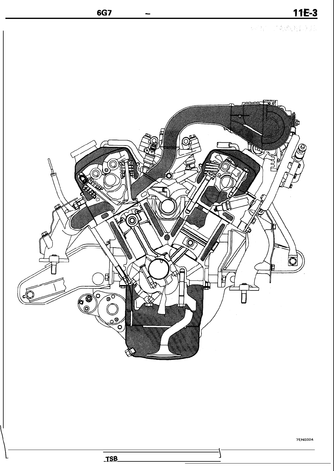
SECTIONAL VIEW
-
SOHC ENGINE for
DIAMANTE
7EN0323
TSB Revision
6G7
ENGINE
-
General Information
llE-3
TEN0324
1%
Revision
\

IIE-4
6G7
ENGINE
-
General Information
SECTIONAL VIEW
-
SOHC ENGINE for MONTERO AND TRUCK
TSB Revision
7EN0135
I

667
ENGINE
-
General Information
TSB Revision
7EN0120
I

WE-6
6G7
ENGINE
-
General Information
SECTIONAL VIEW
-
DOHC NON-TURBO ENGINE
TSB Revision
7EN0325


IIE-8
6G7
ENGINE
-
General Information
SECTIONAL VIEW
-
DOHC TURBO ENGINE
1
TSB Revision
7EN0335

667
ENGINE
-
General Information
IIE-9
TSB Revision
7EN0334

IIE-10
6G7
ENGINE
-
General Information
JJBRICATION
SYSTEM
-
SOHC
/
Oil pressure
switch
\
n
t
Oil pressure
gauge unit
Oil cooler by-pass
valve
-
MONTERO only
Rocke
Lash adjuster
7LUOO34
TSB Revision

667
ENGINE
-
General Information
llE41
UBRICATION
SYSTEM
-
DOHC
To
turbo-
Oil pressure switch
charger
\
-turbo
only
is
Oil pressure
gauge unit
Las
To oil cooler
-
Turbo only
II
Oil cooler by-pass
valve -Turbo only
Relief valve
TSB Revision

WE-12
6G7
ENGINE
-
General Specifications
GENERAL SPECIFICATIONS
SOHC
Description
Specifications
Type
6O”V,
SOHC (per bank)
Number of cylinders
6
Combustion chamber
Compact type
Total displacement
cm3
(cu.in.1
2,972 (181.4)
Cylinder bore
x
stroke
mm (in.)
91
.I
x
76.0 (3.59
x
2.99)
Compression ratio
Front wheel drive vehicle
10.0
Rear wheel drive vehicle
8.9
Valve timing: Front wheel drive
Intake valve
Opens
16” BTDC
Closes
66” ABDC
Exhaust valve
Opens 56” BBDC
Closes
26”
ATDC
Valve timing: Rear wheel drive
Intake valve
Opens
19” BTDC
Closes
59” ABDC
Exhaust valve
Opens
59” BBDC
Closes 19” ATDC
Lubrication system Pressure feed, full-flow filtration
3il pump type
Trochoid type
Cooling system
Water-cooled forced circulation
JVater
pump type
Centrifugal impeller type
EG
R
type
Single type
njector type and number Electromagnetic, 6
njector
identification mark For MONTERO and TRUCK
B210H
For DIAMANTE and TRUCK
N21
OH
Throttle bore
mm (in.) 60 (2.362)
rhrottle position sensor
Variable resistor type
Iosed
throttle position switch Movable contact type
TSB Revision

667
ENGINE
-
General Specifications
DOHC
Description
Type
Number of cylinders
Combustion chamber
Total displacement
cm3
(cu.in.1
Cylinder bore
x
stroke
mm (in.)
Compression ratio Non-turbo
Turbo
Valve timing-Non-turbo
Intake valve
Opens
Closes
Exhaust valve
Opens
Closes
Valve timing -Turbo
Intake valve
Opens
Closes
Exhaust valve
Opens
Closes
Lubrication system
Oil pump type
Cooling system
tiater
pump type
EGR type
Injector type
njector identification mark Non-turbo
Turbo
Throttle bore
mm (in.)
Throttle position sensor
Closed
throttle position switch
Specifications
6O”V.
DOHC (per bank)
6
Compact type
2,972 (181.4)
91.1
x
76.0 (3.59
x
2.99)
10.0
8.0
16” BTDC
55” ABDC
48” BBDC
15” ATDC
16” BTDC
55” ABDC
50” BBDC
17” ATDC
Pressure feed, full-flow filtration
Trochoid type
Water-cooled forced circulation
Centrifugal impeller type
Single type
Electromagnetic, 6
BDH210
BDL360
60 (2.362)
Variable resistor type
Movable contact type
1
TSB Revision
I

IIE-14
6G7
ENGINE
-
Service Specifications
SERVICE SPECIFICATIONS
mm (in.)
Standard
Limit
Cylinder head
-
SOHC
Flatness of gasket surface
Less than 0.05
(.0019)
0.2
(.008)
Grinding limit of gasket surface
*0.2
(.008)
*
Total resurfacing depth of both
cylinder head and cylinder block
Overall height
84 (3.31)
Oversize rework dimensions of valve guide hole
(both intake and exhaust)
0.05
(.002)
13.05-
13.07
(.5138-
.5147)
0.25
(.OlO)
13.25
-
13.27
(5217
-
.5224)
0.50
(.020)
13.50
-
13.52
(.5315
-
.5323)
Oversize rework dimension of valve seat hole
Intake 0.3
(.012)
44.30
-
44.33 (1.7441
-
1.7453)
0.6
(.024)
44.60
-
44.63 (1.7559
-
1.7571)
Exhaust 0.3
(.012)
38.30
-
38.33 (1.5079
-
1.5091)
0.6
(.024)
38.60
-
38.63 (1.5197
-
1.5209)
Cylinder head
-
DOHC
Flatness of gasket surface
Less than 0.03
(.0012)
0.2
(.008)
Grinding limit of gasket surface
“0.2
(008).
*
Total resurfacing depth of both
cylinder head and cylinder block
3verall
height
132
(5.20)
Dversize rework dimensions of valve guide hole
Iboth
intake and exhaust)
0.05
(.002)
12.05
-
12.07
(.4744-
.4752)
0.25
(.OlO)
12.25
-
12.27
(4823
-
.4831)
0.50
(.020)
12.50
-
12.52
l.4921
-
.4929)
3versize rework dimension of valve seat hole
Intake 0.3
(.012)
36.30
-
36.33 (1.4291
-
1.4303)
0.6
(.024)
36.60
-
36.63
(1.4409
-
1.4421)
Exhaust 0.3
(.012)
33.30-33.33(1.3110-1.3122)
0.6
(.024)
33.60
-
33.63 (1.3228
-
1.3240)
Camshaft-
SOHC
Zam
height
Intake
41.25 (1.6240)
40.75
(1.6043)
Exhaust
41.25 (1.6240)
40.75
(1.6043)
lournal
diameter
34 (1.34)
Iii
clearance
0.05
-
0.09
(.0020
-
.0035)
dentification mark
for
DIAMANTE
for MONTERO and TRUCK
!
TSB Revision

667
ENGINE
-
Service
SDecifications
mm (in.)
Camshaft
-
DOHC
Cam height
Intake
Exhaust
Journal diameter
Oil clearance
Rocker arm
-
SOHC
I.D.
Rocker arm-to-shaft clearance
Rocker
shaft
-
SOHC
3.D.
Dverall
length
Valve
-
SOHC
3verall
length
Intake
Exhaust
jtem
diameter
Intake
Exhaust
-ace
angle
stem-to
guide clearance
Intake
Exhaust
-hickness
of valve head (Margin)
Intake
Exhaust
lalve
-
DOHC
Iverall
length
Intake
Exhaust
item
diameter
Intake
Exhaust
ace angle
item-to guide clearance
Intake
Exhaust
hickness of valve head (Margin)
Intake
Exhaust
Standard
35.49(1.3972)*‘,34.91
(1.3744)**
35.20(1.3858)*',34.91 (1.3744)*'
26(1.02)
0.05-0.09(.020-.0035)
18.91
-18.93(.7445-.7453)
0.01
-0.04(.0004-.0016)
18.89-18.90
(.7437-.7441)
333.5(13.130)
102.97 (4.0539)
102.67 (4.0421)
7.96-7.98(.3134-.3142)
7.93-7.95
(.3122-.3130)
45"-45.5"
0.03-0.06(.0012-.0024)
0.05-0.09(.0020-.0035)
1.2
(.047)
2.0
i.079)
106.28(4.1842)
105.40(4.1496)
6.57-6.58(.2587-.2591)
6.53-6.55(.2571
-.2579)
45"-45.5"
0.02-0.05(.0008-.0020)
0.05-0.09
(.0020-.0035)
1
.o
l.039)
1.5
(.059)
Limit
34.99(1.3776)*'
34.41 (1.3547)"'
34.70 (1.3661)"'
34.41
(1.3!%7)"2
0.10(.004)'
.
0.10
(.0039)
0.15
(.0059)
0.7
(.028)
1.5
(.059)
0.10
i.0039)
0.15
i.0059)
0.5(.019)
1
.o
i.039)
NOTE
*I
=
Up to 1992 models
“2 = from 1993 models
TSB Revision
I

IIE-16
667
ENGINE
-
Service
SDecifications
mm (in.)
Standard
Limit
Valve spring
-
SOHC
Free length 49.8 (1.961)
48.8 (1.921)
Load/Installed height
N/mm
(Ibs./in.)
329/40.4
(725/l
.591)
Out-of-squareness Less than 2”
4”
Valve spring - DOHC
Free length
45.2
(1.780)*‘,
46.4 (1.827)“’
44.2 (1.740)*’
45.4 (1.787)“’
Load/installed height
N/mm
(Ibs.in.1
240/37.9
(52.911.492)
Out-of-squareness Less than 2”
4”
Valve guide
-
SOHC
Overall length
Intake
44 (1.73)
Exhaust
48 (1.89)
I.D.
8.00
-
8.02 i.315
-
.316)
O.D.
13.06-
13.07
(.5142-.5146)
Service size
0.05
(.002),
0.25
LO1
0)
0.50
(.020)
Oversize
Valve guide
-
DOHC
Overall length
Intake
Exhaust
I.D.
O.D.
Service size
45.5(1.791)
50.5 (1.988)
6.60
-
6.62
(.2598
-
.2607)
12.06
-
12.07
(.4748
-
.4752)
0.05
(.002),
0.25
LO1
0)
0.50
(.020)
Oversize
Valve seat
Seat angle
valve
contact width
Sinkage
Service size
Piston
-
SOHC
3.D.
‘iston-to-cylinder
clearance
Service
size
44-
44.5”
0.9
-
1.3
(035
-
,051)
0.30
(.012),
0.60
t.024)
Oversize
91
.I
(3.587)
0.02
-
0.04
(.0008
-
.0016)
0.25
(.OlO),
0.50
(.020)
0.75
(.030),
1
.OO
l.039)
Oversize
0.2
‘iston
-
DOHC
3.D.
‘iston-to-cylinder
clearance
Service size
91 .I (3.587)
0.02
-
0.04
(.0008
-
.0016)
0.25
LOlO),
0.50
f.020)
0.75
(.030),
1
.OO
(039) Oversize
NOTE
O.D. = Outer Diameter
I.D. = Inner Diameter
*I
= Up to 1992 models
“2
=
From 1993 models
1
TSB Revision

6G7
ENGINE
-
Service Specifications
,llE-17
mm (in.)
Piston ring
-
SOHC
End gap
No. 1 ring
No. 2 ring
Front wheel drive vehicle
Rear wheel drive vehicle
Oil ring
Front wheel drive vehicle
Rear wheel drive vehicle
Ring to ring groove clearance
No.1
ring
Front wheel drive vehicle
Rear wheel drive vehicle
No.2
ring
Piston ring
-
DOHC
End gap
No.
1
ring
No. 2 ring
Oil ring
?ing
to ring groove clearance
No. 1 ring
No. 2 ring
‘iston
pin
I.D.
‘Tess-in
load
N
(Ibs.)
‘Tess-in
temperature
Connecting
rod
3ig
end center-to-small end center length
3end
‘wist
jig end side clearance
Crankshaft
!nd
play
ournal O.D.
‘in O.D.
jut-of-roundness of journal and pin
Two-camshaft engine
Four-camshaft engine
aper
of journal and pin
)il
clearance of journal
)il
clearance of pin
NOTE
O.D.
=
Outer Diameter
Standard
0.30-0.45(.0118-.0177)
0.45
-
0.60
(.0177
-
.0236)
0.25
-
0.45
LOO98
-
.0177)
0.20
-
0.60
LOO79
-
.0236)
0.20
-
0.70
(.0079
-
.0276)
0.03
-
0.07
LOOI
2
-
.0028)
0.05
-
0.09
(0020
-
.0035)
0.02
-
0.06
(.0008
-
.0024)
0.30
-
0.45
(.0118
-
.0177)
0.45
-
0.60
(.0177
-
.0236)
0.20
-
0.70
(.0079
-
.0276)
0.03
-
0.07
(.0012
-
.0028)
0.02
-
0.06
(.0008
-
.0024)
22.001
-
22.007
(8662
-
.8664)
75.00
-
175.00 (1,653
-
3,858)
Room temperature
Limit
0.8
(.031)
0.8
(.031)
0.8
(.031)
‘I
.o
(.039)
1
.o
(.039)
0.1
(004)
0.1
(004)
0.1
(.004)
0.8
(.031)
1
.o
(.039)
1
.o
(039)
0.1
(.004)
0.1
(.004)
140.9-
141
.o
0.05
(0020)
or less
0.1
(004)
or less
0.10
-
0.25
(.0039
-
.0098)
0.05
-
0.25
(0020
-
.0098)
60 (2.36)
50 (I
.97)
Less than 0.005
(.0002)
Less than 0.003
(.OOOl)
Less than 0.005
(.0002)
0.020
-
0.050 t.0008
-
.0020)
0.020
-
0.050
(0008
-
.0020)
0.4
(.016)
0.3
(.012)
0.1
(.004)
0.1
(.004)
1
TSB Revision

IIE-18
6G7
ENGINE
-
Service
SDecifications
mm (in.)
Cylinder block
Cylinder bore
Flatness of gasket surface
Grinding limit of top surface
*
Total resurfacing depth of both
cylinder head and cylinder block
Standard
91.1 (3.587)
0.05
(.002)
Limit
“0.2
(.008)
Oil pump
Tip clearance
0.03
-
0.08
(0012
-
.0031)
0.35 (0138)
Side clearance
0.04-0.10
(.0016-
.0039)
Body clearance 0.10
-
0.18
(0040
-
.0070)
Drive belt
-
SOHC for
DIAMANTE
Deflection
New belt
4.0-5.0(.157-,197)
Used belt 7.0
(276)
Tension gauge
N
(Ibs.)
New belt 700
-
900 (154
-
198)
Used belt 500 (I
IO)
Drive belt
-
SOHC for MONTERO and TRUCK
Deflection
New belt
6.5
-
8.0
(.256
-
,315)
Used belt
9.0
(.354)
Tension gauge
N
(Ibs.)
New belt
500-700(110-154)
Used belt
400 (88)
Irive
belt
-
DOHC
Ieflection
New belt
3.5-4.0(.138-,157)
Used belt
4.0-5.0(.157-,197)
rension
N
(Ibs.)
New belt
650
-
850 (143
-
187)
Used belt
450
-
500 (99
-
132)
njector
Zoil
resistance
Non-turbo R
13
-
16 at
20°C
(68°F)
Turbo
R
2
-
3 at
20°C
(68°F)
dle
air control motor
Ioil
resistance
R
28
-
33 at
20°C
(68°F)
-hrottle
position sensor
tesistance
kS1
3.5
-
6.5
rccelerator
pedal position sensor
lesistance
kR
3.5-6.5
‘ariable
induction control motor
(esistance
fi
5
-
35 at
20°C
(68°F)
TSB Revision

667’
ENGINE
-
Torque Specifications
TORQUE
SPECIFICATIONS
Generator and drive belt
Cooling fan bolt
Nm
11
ftlbs.
8
.<
Fan pulley bolt
11
8
Tensioner pulley nut
SOHC DIAMANTE, DOHC
50
36
SOHC MONTERO AND TRUCK
45
33
Tensioner bracket bolt
SOHC DIAMANTE
42
30
SOHC MONTERO AND TRUCK
Ml0
24
17.
Ml2
42
30
DOHC
19
14
,,.’
Idler pulley bolt
,’
SOHC MONTERO AND TRUCK
45
33
DOHC
50
36
Cooling fan bracket bolt
42
30
Tensioner bracket stay bolt
24
17
Generator pivot nut
23
17
Generator brace bolt
.F-’
SOHC DIAMANTE
14
IO
SOHC MONTERO AND TRUCK- Side bolt
10
7
-
Exhaust
manifold
tightening side
bolt
13
9
Generator bracket bolt
24
17
45
33
lrankshaft bolt SOHC
155
122
DOHC
185
134.
ntake manifold plenum and throttle body
iGR
pipe bolt
18
13
ntake manifold plenum stay bolt
18
13
!GR
valve bolt
22
16
-hrottle
body bolt
12
8
SOHC MONTERO AND TRUCK
14
10
gnition coil bolt
2.5
1.8
gnition
power transistor bolt
5
3.6
-hrottle body
‘hrottle
position sensor bolt
2
1.4
Ye
air control motor bolt
3.5
2.5
SOHC DIAMANTE DOHC Non-TURBO
2.5
1.8
\ccelerator pedal position sensor bolt
2
1.4
‘acuum
actuator bolt
3.5
2.5
1
TSB Revision

IIE-20
6G7
ENGINE
-
Torque Specifications
Ignition system
Center
cover bolt
Spark plug
Distributor nut
Ignition coil bolt
SOHC MONTERO AND TRUCK
DOHC
Ignition power transistor bolt
DIAMANTE
3000GT
Crankshaft position sensor nut
Timing belt
-
SOHC
Engine support bracket bolt
Ml0
Ml2
Tensioner lock bolt
Camshaft
sprocket bolt
Zenerator stay bolt
3enerator bracket bolt
riming belt - DOHC
Engine
support bracket bolt
Ml0
Ml2
ZrankshaftKamshaft position sensor bolts
4uto
tensioner bolt
rensioner pulley bolt
rensioner arm assembly bolt
dler pulley bolt
dler pulley bracket bolt
jocker
cover bolt
Camshaft
sprocket bolt
ntake manifold and fuel parts
njector
and fuel rail bolt
:uel
regulator bolt
pressure
-uel
pipe bolt
leat
pipe bolt
ngine coolant temperature gauge unit
ngine coolant temperature sensor
SOHC DIAMANTE
hermo
switch
dater outlet fitting bolt
ltake
manifold nut
Jater inlet fitting bolt
hermostat housing bolt
. .
Nm
ft.Ibs.
3
2
25
18
14
10
25
18
13
9
22
16
13
9
12
7
60
43
110
80
29
19
90
65
25
18
25
18
70 ‘51
110
80
9
7
24
17
49
35
42
30
55
40
42
30
3
2
90
65
12
9
9
7
9
7
12
9
30
22
11
8
8
6
8
6
19
14
18
13
19
14
19
14
-
ITSB Revision
1

6G7
,ENGlNE
-
Torque Specifications
Exhaust manifold
Oil level guide bolt
gauge
Heat protector bolt
Engine hanger bolt
SOHC DIAMANTE
SOHC MONTERO AND TRUCK
DOHC NON-TURBO
Exhaust manifold nut
SOHC
DOHC NON-TURBO
DOHC TURBO
Heater pipe bolt
dater
pipe bolt
SOHC MONTERO AND TRUCK
dater
bolt
pump
ieat
protector
C
Turbocharger stay bolt
ixhaust
fitting bolt
3il
pipe bolt
eye
Yare
nut
Nater pipe eye bolt
Xl
return pipe bolt
rurbocharger
‘urbocharger waste gate actuator bolt
locker arms and camshafts - SOHC
>il
filler bolt
locker cover bolt
Iistributor
adaptor bolt
locker arm shaft and bearing cap bolt
Camshafts,
rocker arms and bearing caps- DOHC
lrankshaft position sensor adaptor bolt
learing
caps, front and rear bolt
rearing cap bolts No. 2,
3,4
lylinder
head and valve- SOHC
:ylinder head bolt
:ylinder
head and valve
-
DOHC
:ylinder
head bolt
NON-TURBO
TURBO
Nm
ft.lbs.
14
10
14
10
24
17
19
14
13
9
19
14
45
33
30
22
12
9
14
10
12
9
24
17
30
22
60
43
14
10
17
12
25
18
31
22
9
7
12
9
9
7
9
7
13
9
20 14
24
17
20 14
11
8
110
80
110
80
125
+
Back off
90
+
Back off
+
125
.--*
90
TSB
Revision
I

11
E-22
667
ENGINE
-
Torque Specifications
Nm
ft.lbs.
Oil pan and oil pump
Transmission stay bolt
75 54
Oil pressure switch
DIAMANTE AND
3000GT
19 14
MONTERO AND TRUCK
IO
7
Oil pressure gauge unit
DIAMANTE AND
3000GT
10
7
MONTERO
55
40
Oil cooler by-pass valve
55 40
Oil filter bracket stay bolt
(10x20)
23
17
(8x20)
13
IO
Oil filter bracket bolt
DIAMANTE AND
3000GT
24
17
MONTERO AND TRUCK mark 4 24
17
mark 7
14 10
Drain plug
40
29
Oil bolt
pan
6
4
Oil screen bolt
19 14
Plug
45 33
Oil case bolt
pump
14
10
Oil cover bolt
pump
10
7
Piston and connecting rod
Connecting rod cap nut
52 38
Crankshaft,
flywheel and drive plate
+wheel
bolt
75 54
Irive
plate bolt
75 54
3ear
plate bolt
11
8
3ell
housing cover bolt
9 7
3il
seal case bolt
11
8
3earing
cap stay bolt 48
35
3earing
cap bolt
-
SOHC
79 57
DOHC 93 67
1993
models DOHC -TURBO
74 54
knock
sensor bracket bolt
29
21
knock
sensor
23
17
Bracket
Knock
sensor
-
DIAMANTE and
3000GT
23
17
knock
sensor bracket bolt
-
DIAMANTE and
3000GT
29
21
loll stopper bracket
-
M
10
42 30
Ml2
75
54
TSB Revision

667
ENGINE
-
Sealant
SEALANT
‘”
,. )
Items
Specified sealant
Auto tensioner bolt -Turbo
3M
ATD Part No. 8660
Engine coolant temperature sensor
3M
NUT Locking Part
No.41
71
Engine coolant temperature gauge unit
3M
ATD Part No.8660
Rocker cover
3M
ATD Part No.8660
Bearing cap
3M NUT Locking Part
No.41
71
Oil pressure switch
3M
ATD Part No.8660
Oil pressure gauge unit
3M
ATD Part No.8660
Oil pan
MITSUBISHI GENUINE Part No.MD970389
Oil seal case
MITSUBISHI GENUINE Part No.MD970389
Quantity
As required
As required
As required
As required
As required
As required
As required
As required
As required
,
TSB Revision

11
E-24
6G7
ENGINE
-
SDecial
Tools
SPECIAL
TOOLS
MD99871
9 or
SOHC engine only
Leak-down tester
Air bleed wire
Camshaft oil
seal installer
For SOHC
engine only
ton and timing
belt
For SOHC engine only
TSB Revision

8G7
ENGINE
-
Special Tools
Tool
Number and
tool name
Supersession
MD99871
7
Crankshaft
front oil seal
installer
I
MD99871
8
Crankshaft
rear oil seal
installer
MD998719
Pulley holding
pins (2)
MD998727
Oil pan
remover
M D998729
Valve stem
seal installer
MD998735
Valve spring
compressor
M D998754
Pulley holding
pins
(2)
MD998761 MD998761-01
Camshaft oil
seal installer
M
D998762
Circular packing
installer
MD99871
7-01
MD998718-01
Use with
MB990938,
01
MIT308239
MD998735-01
M
IT308239
I
Installation of crankshaft rear oil seal
iolding
camshaft sprocket when loosening
x
torquing bolt
-or
SOHC engine only
f
qemoval
of oil pan
nstallation of valve stem seal
:or
SOHC engine only
lemoval and installation of valve and
re-
jted
parts
l-
lolding
crankshaft sprocket when
loosen-
ir
lg
or torquing bolt
lstallation of camshaft oil seal
or DOHC engine only
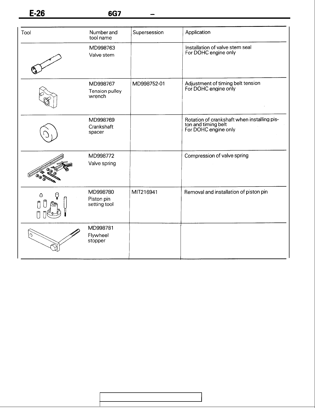
Application
Installation of crankshaft front oil seal
M
D998762-01
Installation of circular packing
For DOHC engine only
TSB Revision
11
E-26
6G7
ENGINE
-
Special Tools
seal installer
compressor
Installation of flywheel
TSB Revision

667
ENGINE
-
Generator and Drive Belt
GENERATOR AND DRIVE BELT
REMOVAL AND INSTALLATION
-
SOHC for
DIAMANTE
1
3
2
30
ft.lbs.
il
7
155
Nm
112
ft.lbs.
23
Nm
8
I
14
Nm
10
ft.lbs.
Removal steps
+A4
I.
Drive belt
2.
Tensioner pulley
3.
Adjusting bolt
4.
Adjusting stud
5.
Tensioner bracket
6.
Pivot bolt
7.
Generator
8.
Generator brace
QArJ
+B4
9. Crankshaft bolt
10.
Special washer
11.
Crankshaft pulley
7EN0487
1
TSB Revision
I

IIE-28
6G7
ENGINE
-
Generator and Drive Belt
tEMOVAL
AND INSTALLATION
-
SOHC for MONTERO and TRUCK
12
13
Nm
9
ftlbs.
I
I
IONm
7 ftlbs.
Removal steps
13
Nm
9
ftlbs.
13
1.
Drive belt
2.
Cooling fan
3.
Fan clutch
4. Fan pulley
5.
Idler pulley
6.
Tensioner pulley
7.
Adjusting bolt
8.
Adjusting stud
9.
Tensioner bracket
0. Cooling fan bracket assembly
1. Tensioner bracket stay
2.
Generator brace
3.
Generator
4.
Crankshaft bolt
5.
Special washer
6.
Crankshaft pulley
7EN0488
TSB Revision

6G7
ENGINE
-
Generator and Drive Belt
IEMOVAL
AND INSTALLATION
i
DOHC
23
Nm
17
ft.lby
24 Nm
17 ftlbs.
24
Nm
17
ft.lbs.
I
4
8
I
45 Nm
33
ft.lbs.
50
Nm
2
36
klbs.
\
50
Nm
I
165
Nm
134ft.lbs.
Removal steps
#A4
1.
Drive belt
2.
Idler pulley
3.
Tensioner pulley
4.
Adjusting bolt
5.
Adjusting stud
6.
Tensioner bracket
7.
Generator
8.
Generator bracket
9.
Bracket
(IA(J
#64
IO.
Crankshaft bolt
11.
Special washer
12.
Crankshaft pulley
7EN0489
TSB Revision

WE-30
6G7
ENGINE
-
Generator and Drive Belt
SOHC for
DIAMANTE
NTERO and TRUCK
DOHC
IOON
7EN0349
REMOVAL SERVICE POINT
(JAO
CRANKSHAFT BOLT LOOSENING
(1) Using the special tool, hold the drive plate or flywheel.
(2)
Remove the crankshaft bolt.
INSTALLATION SERVICE POINT
#A4
DRIVE BELT TENSION ADJUSTMENT
DRIVE BELT
-
TENSION CHART
Generator
drive belt
SOHC for
New
DIAMANTE
USed
SOHC for
New
MONTERO
USed
and TRUCK
DOHC
New
Used
I
Deflection
mm (in.)
I
TenEo;bt;uge
4.5
(.16-.20)
700-900(154-198)
7
l.28)
500 (110)
6.5-8.0(.26-.32)
500-700(110-154)
9(.35)
400(88)
3.5-4.0(.14-.16)
650-850(143-187)
4-5(.16-.20)
450-600(99-132)
TSB Revision
(1)
Loosen the tensioner pulley locking nut.
(2) Tighten the adjusting bolt to adjust the belt
deflectbn
to the
specification shown in the chart.

6G7
ENGINE
-
Generator and Drive Belt
SOHC
for
DIAMANTE-
w
gauge
Tension’
w
7EN0399
SOHC
for MONTERO and TRUCK
7EL0070
DOHC
(3) If you use a tension gauge, tighten the adjusting
bblt
to
adjust the belt tension to the specification shown in the
chart.
.:.
I)B4
CRANKSHAFT BOLT TIGHTENING
(1)
Using the special tool, hold the drive plate or flywheel.
(2) Install the crankshaft bolt.
TSB Revision
1

11
E-32
6G7
ENGINE
-
Intake Manifold Plenum and Throttle Body
INTAKE MANIFOLD PLENUM AND THROTTLE BODY
REMOVAL AND INSTALLATION
-
SOHC for
DIAMANTE
8
18
Nm
12
Nm
8
ft.lbs.
I
5Nm
3.6
ft.lbs.
22
Nm
16
ftlbs.
18Nm
13
ft.lbs.
Removal steps
1.
EGRpipe
2. Ignition coil
For California
3. High tension cable
4. Intake manifold plenum stay, rear
5. Intake manifold plenum
stay,
front
6.
EGR valve
7. EGR valve aasket
1
For California
8.
Throttle body
9. Throttle body gasket
10.
Ignition power transistor
11. Intake manifold plenum
12. Intake manifold plenum gasket
7EN0405
TSB Revision

6G7
ENGINE
-
Intake Manifold Plenum and Throttle Body
IEMOVAL
AND INSTALLATION
-
SOHC for MONTERO and TRUCK
14
Nm
10
ft.lbs.
tr-
18
Nm
13
ft.lbs.
18
Nm
Removal steps
1. EGR pipe
2.
EGR pipe gasket
I
For California
3.
Intake
inariifold plenum stay, rear
4. Intake manifold plenum stay, front
5.
EGR valve
6. EGR valve gasket
>
For California
7. Throttle body
8. Throttle body gasket
9. Intake
manifold
plenum
10. Intake manifold plenum gasket
22
Nm
16
ft.lbs.
7EN0408
TSB Revision

11
E-34
6G7
ENGINE
-
Intake Manifold Plenum and Throttle Body
{EMOVAL
AND INSTALLATION
-
DOHC NON-TURBO
6
12 Nm
8
ft.lbs.
I
8Nm
3 ftlbs.
22 Nm
16
ft.lbs.
18Nm
13
ft.lbs.
3
18Nm
13 ftlbs.
Removal steps
1.
EGR pipe
For California
2. Intake manifold plenum stay, rear
3. Intake manifold plenum stay, front
5.
EGR valve
6. EGR valve gasket
I
For California
7. Throttle body
8. Intake manifold plenum
9. Intake manifold plenum gasket
Cb,18Nm
13
fklbs.
TSB Revision
7EN0411

IEMOVAL
AND FUEL SYSTEM
-
DOHC TURBO
m2-?&
18hm
13 ftlbs.
18Nm
13
ft.lbs.
Removal steps
1.
EGRpipe
2. EGR pipe gasket
j
For California
3. Intake manifold plenum stay, rear
4. Intake manifold plenum stay, front
5.
EGR valve
6. EGR valve aasket
I
For California
7. Throttle
bo?iy
8. Throttle body gasket
9.
Intake
manifold plenum
10.
Intake manifold plenum gasket
18 Nm
13
ftlbs.
6G7
ENGINE
-
Intake Manifold Plenum and Throtiib
B’ijdy
qq-ps5
1
TSB
Revision
I
I .
1

11
E-36
6G7
ENGINE
-
Intake Manifold Plenum and Throttle Body
6EM0384
INSPECTION
EGR VALVE
(1)
Check the EGR valve for sticking or carbon deposits.
If such conditions exist, clean or replace the EGR valve.
(2) Connect a hand vacuum pump to the nipple of the EGR
valve and plug other nipple.
(3) If there is vacuum leakage, replace the EGR valve.
(4) Blow air in from one passage of the EGR to check its
condition as follows.
TSB Revision

THROTTLE BODY
667 ENGINE
-
Throttle Body
n-E-37
DISASSEMBLY AND REASSEMBLY
-
SOHC for DIAMANTE, DOHC NON-TURBO
2Nin
1.4ft.lbs.
2.5 Nm
1.8
ft.lbs.
Disassembly steps
QArJ
+A4
1. Throttle position sensor
2. Idle air control motor
@O
3. Throttle body
7FU1282
DISASSEMBLY AND REASSEMBLY
-
For VEHICLES with TRACTION CONTROL
!Nm
1.4
ft.lbs.-
4
I
ii+--
3.5 Nm
2.5 ftlbs.
3.5 Nm
2.5
ft.lbs.
5
Disassembly steps
1. Water hose
#B4
6. Throttle body
1.4
ft.lbs.
sensor
7FU1283
TSB Revision

11
E-38
6G7
ENGINE
-
Throttle Body
DISASSEMBLY AND REASSEMBLY
-
DOHC TURBO
Disassembly steps
Up to 1992 models
3.
Vacuum valve
4.
Dash
pot-
From 1993
models
(IAO
)A4
5. Throttle position sensor
6.
Idle
air control motor
0
7.
Throttle body
DISASSEMBLY AND REASSEMBLY
-
SOHC for MONTERO and TRUCK
3
I
n
1
cz!J
/T’
Disassembly steps
OAO
)B4
1.
Throttle position sensor
(Within closed throttle position switch)
2. Idle air control motor assembly
3. Throttle body
3.5
Nm
2.5 ftlbs.
2Nm
1.4
ft.lbs.
1
TSB Revision
7FUO532
I

6G7
ENGINE
-
Throttle Body
DISASSEMBLY SERVICE POINTS
OAo
THROlTLE
POSITION SENSOR, ACCELERATOR
PEDAL POSITION SENSOR AND IDLE AIR CONTROL
MOTOR REMOVAL
(1)
Do not
d’
rsassemble
the sensor and motor.
(2)
Do not clean the sensor and motor by dipping them into the
solvent. Clean them with shop towel.
\
7FU105i
(%r)
THROlTLE
BODY REMOVAL
(1) Do not remove the throttle valve.
(2) Check if the vacuum port or passage is clogged. Use
compressed air to clean the vacuum passage.
INSPECTION
DASH POT
-
DOHC TURBO
Up to 1992 models
(1) Push the rod of the dash pot all the way in and close the
nipple with the fingers,
(2)
If the rod does not protrude after releasing it, the dash pot is
functioning normally.
(3) If the rod protrudes, a broken diaphragm is suspected.
Therefore, replace the dash pot.
From 1993 models
(1) Push the dash pot rod in lightly and confirm the resistance.
NOTE
1.
Resistance increases as the rod is pushed harder.
2. If the rod can be pushed in with no resistance, either
the diaphragm or check valve is faulty.
(2) Release finger and confirm that the rod returns to its
original position quickly.
NOTE
If the rod returns slowly, the check valve is faulty.
TSB Revision

IIE-40
6G7
ENGINE
-
Throttle Bodv
6EM069
Red
M
D998463
7FUO29(
Idle
air
mot01
MD998463
7FUOO71
VACUUM VALVE
-
DOHC TURBO
Up to 1992 models
(1)
Remove the filter from the vacuum valve.
(2) Connect a hand vacuum pump to the black nipple of the
vacuum valve.
(3) With the other nipple closed by the finger, apply a negative
pressure of 500
mmHg
(19.7
in.Hg.)
to make sure that the
negative pressure is maintained.
(4)
Let go your finger and make sure that the negative pressure
leaks out gradually.
(5) Disconnect the hand vacuum pump and connect it to the
green nipple.
(6) Make sure that the negative pressure leaks out as soon as it
is applied.
(7) Remove the hand vacuum pump from the valve.
(8) Install the filter onto the black nipple of the valve.
IDLE AIR CONTROL MOTOR
Checking the Coil Resistance
(1) Connect Test Harness to the motor connector.
(2) Measure the resistance between the white clip of Test
Harness and the red clip or blue clip.
Standard value: 28
-
33
LR
at
20°C
(68°F)
(3)
Measure the resistance between the green clip of Test
Harness and the yellow clip or black clip.
Standard value: 28
-
33
LR
at
20°C
(68°F)
Operational Check
(1)
Connect Test Harness to the idle air control motor
connector.
(2) Connect the positive
0
terminal of 6 volt battery to the
white clip and the green clip of Test Harness.
1
TSB Revision
I

6G7
ENGINE
-
Throttle Body
1
gs41
7FUO29f
w
“’
7FUlb3Z
I
(3) Hold the idle air control motor as shown in the illustration,
connect the negative
0
terminal of the power supply to
each clip as described in the following steps, and check
whether or not a vibrating feeling (a feeling of very slight
vibration of the stepper motor) is generated as a result of
the activation of the stepper motor.
@
Connect the negative
0
terminal of the power supply to
the red and black clip.
@ Connect the negative
0
terminal of the power supply to
the blue and black clip.
@ Connect the negative
0
terminal of the power supply to
the blue and yellow clip.
@ Connect the negative
0
terminal of the power supply to
the red and yellow clip.
@ Connect the negative
0
terminal of the power supply to
the red and black clip.
@ Repeat the tests in sequence from @ to
0.
(4) If, as a result of these tests, vibration is detected, the
stepper motor can be considered to be normal.
CHECKING VACUUM ACTUATOR
-
VEHICLES with TRACTION CONTROL
(1)
With the throttle valve opened, apply a vacuum of 200
mmHg (7.9
in.Hg.)
to the vacuum actuator to make sure
that the throttle valve closes.
(2) Then lower the level of vacuum gradually to make sure that
the vacuum actuator opens.
REASSEMBLY SERVICE POINTS
I)A4
THROTTLE POSITION SENSOR
(TPS)
INSTALLATION
-
SOHC for DIAMANTE, DOHC
(1)
Install the throttle position sensor to the throttle body as
shown in the illustration.
(2) Turn the throttle position sensor 90” clockwise to set it, and
tighten the screws.
TSB Revision

11
E-42
6G7
ENGINE
-
Throttle Bodv
Throttle position
Ground
I
Throttle position
sensor
output
Closed throttle
position switch
7FU053E
7FUO53:
I
I
I
7FUO53L
Ground
\
Throttle position
sensor
outmt
Closed throttle
position switch
\
Throttle position
sensor power
7FU053E
(3) Connect a circuit tester between 4 (ground) and 2 (output),
or between 2 (output) and 1 (power). Then, make sure that
the resistance changes smoothly when the throttle valve is
slowly moved to the fully open position.
(4) Check for continuity across terminals 3 (closed throttle
position switch) and 4 (ground) with the throttle valve both
fully closed and fully open.
Throttle valve position
Fully closed
Continuity
Conductive
Fully open
I
Non-conductive
I
If there is no continuity with the throttle valve fully closed,
turn TPS counterclockwise, and then check again.
NOTE
Some throttle position sensors are not provided with the
position switch. In that case, the check described in step (4)
cannot be accomplished.
(5) If the above specifications are not met, replace TPS.
I)B4
;rNHslA~-EP$tSITION SENSOR (TPS)
-
SOHC for MONTERO and TRUCK
(1)
Install the throttle position sensor to the throttle body as
shown in the illustration.
(2) Turn the throttle position sensor 90” counterclockwise to
set it, and tighten the screws.
!I
(3) Connect a circuit tester between
@
(ground) and
@
(output), or between @ (output) and @ (power). Then,
make sure that the resistance changes smoothly when the
throttle valve is slowly moved to the fully open position.
(4) Check for continuity across terminals @ (closed throttle
position switch) and @ (ground) with the throttle valve both
fully closed and fully open.
TSB Revision
1

6G7
ENGINE
-
Throttle Body
w43
7FU1071
7FU107:
Closed throttle
Accelerator
pedal position
sensor output
7~~053~
)r”““-’
If there is no continuity with throttle valve fully closed, turn
the throttle position sensor clockwise, and then check
again.
(5) If the above specifications are not met, replace TPS.
I)c4
ACCELERATOR PEDAL POSITION SENSOR
(APS)
INSTALLATION
(1)
Install the accelerator pedal position sensor to the throttle
body as shown in the illustration.
(2) Turn the accelerator pedal position sensor 90” clockwise to
set it, and tighten the screws.
(3) Connect a circuit tester between (ground) and (output), or
between (output) and (power). Then, make sure that the
resistance changes smoothly when the throttle valve is
slowly moved to the fully open position.
(4) Check for continuity across terminals (closed throttle
position switch) and (ground) with the throttle valve both
fully closed and fully open.
Throttle valve position
Continuity
Fully closed
Conductive
Fully open
Non-conductive
If there is no continuity with the throttle valve fully closed,
turn APS counterclockwise, and then check again.
(5) If the above specifications are not met,
rep!ace
APS.
1
TSB Revision

11
E-44
6G7
ENGINE
-
Ignition System
IGNITION SYSTEM
SOHC for
DIAMANTE
25 Nm
18
ft.lbs.
Removal steps
1. Spark plug cables
2. Spark plug
3. Distributor
4. O-ring
7EN0406
TSB Revision
I

6G7
ENGINE
-
Ignition Svstem
;OHC
for MONTERO AND TRUCK
25
Nm
18
ft.lbs.
Removal steps
1. Spark plug cables
2.
Spark plugs
3. High tension cable
*A4
4.
Distributor
5.
O-ring
6.
Ignition coil
7EN0409
\
TSB
Revision
I

11
E-46
667
ENGINE
-
Ignition System
IOHC
for
DIAMANTE
AND
3000GT
13
Nm
9
ft.lbs.
Removal steps
1.
Center cover
2. Spark plug cables
3.
Soark
oluas
4.
Ciamp’
um
From
5.
Ignition
1993
coil
models
6.
Engine hanger
7.
Ignition
power transistor-
DIAMANTE
eB4
8. ignition power transistor
_
3000GT
9. Crankshaft position sensor- Up to 1992 models
10.
O-ring
7EN0492
I
I
L
I
1
TSB Revision

6G7
ENGINE
-
Ignition Svstem
WE-47
INSTALLATION SERVICE POINTS
I)A4
DISTRIBUTOR INSTALLATION
-
SOljC
(1) Turn the crankshaft so that the No. 1 cylinder is at
compression top dead center.
(2) Align the distributor housing and gear mating marks.
(3) With the stud located in the center of the adjusting slot at
the distributor, install the distributor.
Mating mark
7FI
OOWi
I
I)B4
;;RAFKSHAFT
POSITION SENSOR INSTALLATION
-
(1) Turn the crankshaft so that the No.
1
cylinder is at
compressi,on
top dead center.
(2) Install, lining up the matchmarks on the crankshaft position
sensor housing and the coupling.
TSB Revision

11
E-48
6G7
ENGINE
-
Timing Belt
-
SOHC
TIMING BELT
-
SOHC
REMOVAL AND INSTALLATION
-
DIAMANTE
110
Nm
80 ftlbs.
4F
6
I
26
Nm
19
ft.lbs.
Removal steps
+D4
1. Engine support bracket
2. Access cover
3. Timing belt front upper cover, right
4. Timing belt cover cap
5. Timing belt front upper cover, left
6. Timing belt front lower cover
7. Flange
4AO
&CC
8. Timing belt
iB4
9. Tensioner
10. Tensioner spring
11. Crankshaft sprocket
QBrJ
#A4
12. Camshaft sprocket bolt
13. Camshaft sprocket
14. Timing belt rear cover, left
15. Timing belt rear cover, right
7EN0493
TSB Revision

6G7
ENGINE
-
Timing
Belt
-
SOHC
IEMOVAL
AND INSTALLATION
-
MONTERO AND TRUCK
11
Nm
8 ftlbs.
25
Nm
14
18
ft.lbs.
I
19
ft.lbs.
4
Removal steps
1. Access cover
2. Timing belt front upper cover, right
3. Timing belt front upper cover, left
4. Timing belt front lower cover
5. Flange
@IO
#C4
6. Timing belt
eB4
7.
Tensioner
8. Tensioner spring
9. Crankshaft sprocket
(IBIJ
+A4
10.
Camshaft sprocket bolt
11.
Camshaft sprocket
12. Timing belt rear upper cover, left
13. Generator stay
14. Generator bracket
7EN0494
TSB
Revision

WE-50
6G7
ENGINE
-
Timing Belt
-
SOHC
MB990775-01
EJ
G
000
008
,
REMOVAL SERVICE POINTS
(IAO
TIMING BELT REMOVAL
(1)
Mark the belt running direction for reference in reinstalla-
tion.
NOTE
(1)
Water or oil on the belt shortens its life drastically, so
the removed timing belt, sprocket, and tensioner must
be kept free from oil and water. Do not immerse parts in
cleaning solvent.
(2) If there is oil or water on any part, check the front case
oil seal, camshaft oil seal and water pump for leaks.
~BI)
CAMSHAFT SPROCKET BOLT REMOVAL
Abnormal wear
(Fluffy strand)
INSPECTION
TIMING BELT
Replace belt if any of the following conditions exist.
(1) Hardening of back rubber-back side is glossy without
resilience and leaves no indent when pressed with finger-
nail.
(2) Cracks on rubber back
(3) Cracks or peeling of canvas
(4) Cracks on tooth bottom
(5) Cracks on belt
(6) Abnormal wear of belt sides. The sides are normal if they
are sharp as if cut by a knife.
TSB Revision

6G7
ENGINE
-
Timing Belt
-
SOHC
Rubber exposed
Tooth missing and
canvas fiber exposed
01w70:
(7) Abnormal wear on teeth
(8) Tooth missing and canvas fiber exposed.
INSTALLATION SERVICE POINTS
+A4
CAMSHAFT SPROCKET BOLT INSTALLATION
I)B4
TIMING BELT TENSIONER INSTALLATION
(1) Insert a screwdriver into the hole of the timing belt
tensioner arm, move it all the way in the direction of the
arrow, and tighten the tensioner lock bolt to temporarily
hold this position.
1
TSB Revision
I

11
E-52
6G7
ENGINE
-
Timina Belt
-
SOHC
I)cg
TIMING BELT INSTALLATION
(1)
Align the timing marks of the camshaft sprockets and the
crankshaft sprocket.
(2) Install the timing belt on the crankshaft sprocket first and
while keeping the belt tight on the tension side, install the
belt on the left camshaft sprocket.
(3) Then, install on the water pump pulley and on the right
camshaft sprocket and finally on the timing belt tensioner.
Timing mark
(on belt cover)
Timing mark
(on rear cover or
generator bracket)
/
Camshaft sprocket
(wht)
Timing belt tensioner
(on front
case)
Crankshaft sprocket
(on sprocket)
side
I
ImIng
maw
(on sprocket)
\
Camshaft
(left)
sprocket
(4) Install the flange onto the front end of the crankshaft.
(5) Install the special tool onto the crankshaft.
(6) Loosen the tensioner lock bolt one or two turns and allow
the spring to tension the timing belt.
(7) Turn the crankshaft two full turns clockwise. Turn smoothly
and in clockwise direction only.
(8) Again line up the timing marks on the sprockets and tighten
the tensioner lock bolt to the specified torque.
TSB Revision

6G7
ENGINE
-
Timing Belt
-
SOHC
ad
,I
mark
7EN024:
il
I)D4
ENGINE SUPPORT BRACKET INSTALLATION
-
DIAMANTE
(I)
Tighten the engine support bracket bolts in the order shown
in the illustration.
NOTE
The bolt used at the location shown in the illustration is a
reamer bolt (head mark
“R”).
\
TSB
Revision

11
E-54
6G7
ENGINE
-
Timing Belt
-
DOHC
TIMING BELT
-
DOHC
REMOVAL AND INSTALLATION
-
Up to 1992 models
3Nm
2
ft.lbs.
24
17
90 Nm
65 ftlbs.
RS.
15
A
/
6
49
Nm
35
ft.lbs.
i
30
ft.lbs.
55 Nm
40 ftlbs.
Removal steps
I)E4
1. Engine support bracket
2. Timing belt front upper cover, right
3. Timing belt front upper cover, left
4. Timing belt front lower cover
4AO
$04
5. Timing belt
+C4
6. Auto tensioner
7. Tensioner pulley
8. Tensioner arm assembly
9. Idler pulley
10.
Idler pulley bracket
11. Crankshaft sprocket
#B4
12. Rocker cover
13. Rocker cover gasket, A
14. Rocker cover gasket,
B
(IB~J
*A4
15. Camshaft sprocket bolt
16. Camshaft sprocket
17. Timing belt rear cover, right
18. Timing belt rear cover, left
19. Bracket
20. Timing belt rear cover, center
7EN0497
TSB
Revision
I

667
ENGINE
-
Timing Belt
-
DOHC
tEMOVAL
AND INSTALLATION
-
From 1993 models
3Nm
2
klbs.
3Nm
2
ft.lbs.
24 Nm
17
ft.lbs.
25
10
15
r
1
14
55
Nm
42 Nm
46Nm
30 ft.lbs.
35
ft.lbs.
40 ft.lbs.
IlONm
60 ft.lbs.
ap
+C4
9. Auto tensioner
IO.
Tensioner
nrrllev
11.
Tensioner arm assembly
12.
5
Idler pulley
13. Idler pulley bracket
2
14.
Crankshaft
sprocket
15. Sensing plate
16.
Washer
Removal steps
eE4
1. Engine support bracket
2. Crankshaft position sensor bracket
3. Timing belt front upper cover, right
4. Timing belt front upper cover, left
5. Timing belt front lower cover
OAo
eD4
6. Timing belt
7. Crankshaft position sensor
8. Camshaft position sensor
#B4
17. Rocker cover
18. Rocker cover gasket, A
19. Rocker cover gasket,
B
(rBr)
+A4
20. Camshaft sprocket bolt
21. Camshaft sprocket
22. Camshaft sprocket
23. Timing belt rear cover, right
24. Timing belt rear cover, left
25. Bracket
26. Timing belt rear cover, center
7ENO498
r
1
TSB Revision

6G7
ENGINE
-
Timina Belt
-
DOHC
7EN0224
7ENO775
REMOVAL SERVICE POINTS
aA0
TIMING BELT REMOVAL
(1)
Mark the belt running direction for reference in reinstalla-
tion.
NOTE
(1) Water or oil on the belt shortens its life drastically, so
the removed timing belt, sprocket, and tensioner must
be kept free from oil and water. Do not immerse parts in
cleaning solvent.
(2) If there is oil or water on any part, check the front case
oil seal, camshaft oil seal and water pump for leaks.
OBr)
CAMSHAFT SPROCKET BOLT REMOVAL
(1)
Hold the hexagonal portion of the camshaft with a wrench,
when removing the camshaft sprocket bolt.
INSPECTION
TIMING BELT
Refer to “INSPECTION” on page
IIE-50.
AUTO-TENSIONER
(1)
Check for oil leaks. If oil leaks are evident, replace the
auto-tensioner.
(2) Check the rod end for wear or damage and replace the
auto-tensioner if necessary.
(3)
Measure the rod projection length. If the reading is outside
the standard value, replace the auto tensioner.
Standard value: 11.7
-
12.3 mm
(.461
-
.484
in.)
(4) Use a vice to force the auto tensioner rod in. If the rod
slides in easily, replace the tensioner. If there is nothing
wrong, the rod will offer considerable resistance.
TSB Revision

6G7
ENGINE
-
Timing Belt
-
DOHC
ljl51
;_,
Apply sealant
7-G
7EN024
7EN024’
I
II
I
7EN022E
Spark plug holes
7EN022i
INSTALLATION SERVICE POINTS
I)A4
CAMSHAFT SPROCKET BOLT TIGHTENING
(1)
Hold the hexagonal portion of the camshaft with a wrench
when tightening the camshaft sprocket bolt. Tighten the
bolt to the specified torque.
+B4
ROCKER COVER INSTALLATION
(1)
Apply sealant to the areas shown in the illustration.
Specified sealant: 3M ATD Part
No.8660
or equivalent.
(2) Tighten the rocker cover bolts in the sequence shown in the
illustration.
I)c4 AUTO-TENSIONER INSTALLATION
If the auto-tensioner rod is fully extended, set it in the retracted
position with the following procedure.
(1)
Set the auto tensioner in a vice.
(2) Slowly close the vice to force the rod in until the set hole (A)
of the rod is lined up with the set hole
(B)
of the cylinder.
(3) Insert a wire [I
.4
mm
(.055
in.) in diameter] into the set
holes.
(4)
Remove the auto tensioner from the vice.
(5) On engines with turbocharger, apply sealant to the threads
of the auto tensioner mounting bolt.
Specified sealant:
3M
ATD Part No.8660 or equivalent.
TSB Revision

11
E-58
6G7
ENGINE
-
Timing Belt
-
DOHC
I)04
TIMING BELT INSTALLATION
(1) Using the special tool, line up the crankshaft sprocket
timing marks, and then rotate the sprocket one tooth
counterclockwise.
(2) Line up the timing marks of the camshaft sprockets for left
bank.
(3) Using two wrenches, line up the timing marks of the
camshaft sprockets for right bank.
Caution
1. Since valve spring force can turn the camshaft
sprocket, be careful not to catch your finger.
2.
If either camshaft sprocket is rotated one complete
turn clockwise or counterclockwise after lining up
the timing marks of the other camshaft sprocket,
the intake and exhaust valves might interfere.
Consequently, if a camshaft sprocket was turned
too far in lining up the timing marks, be sure to
rotate it back from that position to line up again the
timing marks.
(4) Install the timing belt on the exhaust side camshaft
sprocket for right bank and hold it with a paper clip at the
position shown in the illustration.
(5) Install the timing belt on the intake side camshaft sprocket
and hold it with a paper clip at the positions shown in the
illustration.
Caution
Since the camshaft sprocket turns easily, avoid exces-
sive pulling on the timing belt.
TSB Revision

6G7
ENGINE
-
Timing Belt
-
DOHC
(6) Check that the timing marks of the camshaft sprockets for
left bank are in alignment. Then install the timing belt on
these sprockets and hold it with a paper clip at the positions
shown in the illustration.
(7) Install the timing belt on the idler pulley.
(8) Install the timing belt on the crankshaft sprocket.
(9) Install the timing belt on the tensioner pulley.
(1O)Using
the special tool, rotate the tensioner pulley clockwise
to tighten the center bolt.
(1 l)Remove the four paper clips.
(12)Using
the special tool, turn the crankshaft a quarter turn
counterclockwise. Then rotate it clockwise to line up the
timing marks and check that all the timing marks are in
alignment.
1
TSB Revision

11
E-60
6G7
ENGINE
-
Timing Belt
-
DOHC
Timing marks
(on right
rocker cover)
Camshaft sprocket
Timing marks
(on left rocker cover)
Auto tensioner
Timing mark (on oil pump case)
(on sprocket)
Timing mark
(on sprocket)
Crankshaft sprocket
’
7EN0235
(13)Loosen
the center bolt of the auto-tensioner pulley, and
install the special tool and a torque wrench on the
pull’ey.
While holding the pulley with approximately
10
Nm (7
ftlbs.)
torque to prevent it from turning, tighten the center
bolt to the specified torque.
(14)Turn
the crankshaft two turns clockwise, and leave it alone
for about five minutes. Then move in and out the
auto-tensioner setting metal wire to check that the wire
moves smoothly.
NOTE
If the metal wire does not move smoothly, repeat step (12)
until it does move smoothly.
(15)Remove
the auto tensioner setting metal wire.
TSB Revision

6G7
ENGINE
-
Timing Belt
-
DOHC
ad mark
I,
7EN024:
(16)Check
that the spacing between the tensioner
arm
antfaulo
tensioner is within the standard limit.
*.
Standard value: 3.8
-
4.5 mm
(.I50
-
.I77
‘in.)
r)E4
ENGINE SUPPORT BRACKET INSTALLATION
(1)
Tighten the engine support bracket bolts in the order shown
in the illustration.
NOTE
The bolt used at the location shown in the illustration is a
reamer bolt (head mark
“R”).
TSB
Revision
I

11
E-62
6G7 ENGINE
-
Intake Manifold and Fuel
Parts
INTAKE MANIFOLD AND FUEL PARTS
REMOVAL AND INSTALLATION
-
SOHC for
DIAMANTE
I/
9Nm
7 ftlbs.
-@-I-
10
I2
__/J
8Nm
/
8
ftlbs.
,I5
c1
19 Nm
14 ftlbs.
16
18
Removal steps
1.
injector harness
2. Injector and fuel rail
3.
insulator
eG4
4. Fuel pressure regulator
5. O-ring
6. Insulator
eF4
87.
lnj;e;rs
9:
Gromet
10.
Fuel pipe
11. O-ring
12. Fuel rail
*D4
13.
Engjne
coolant temperature gauge unit
+C4
14.
Engrne
coolant temperature sensor
*I34
15.
Therm0
switch
16. Water outlet fitting
17. Water outlet fitting gasket
18. Thermostat
19. Intake manifold
20. Intake manifold gasket
7EN0499
1
TSB Revision
7

6G7
ENGINE
-
Intake Manifold and Fuel Parts
IEMOVAL
AND INSTALLATION
-
SOHC for MONTERO AND TRUCK
19Nm
14
ft.lbs.
18
30
Nm
22
c.lbs.
11 Nm
8 ftlbs.
8Nm
-
47-
6lklbs.
d
12Nm
g
)f~~bs~
Removal steps
1. Injector and fuel rail
12. Heat pipe
2.
Insulator
13.
Heat pipe gasket
eG4
3. Fuel pressure regulator
14. Water hose
4. O-ring
eD4
15. Engine coolant temperature gauge unit
5. Insulator
eC4
16. Engine coolant temperature sensor
)F4
6.
Injectors
eB4 17.
Therm0
switch
7.
O-ring
18.
Water outlet fitting
8.
Gromet
19.
Water outlet fitting
gasket
9.
Fuel rail
20.
Thermostat
10.
Water hose
A
21.
Intake manifold
Il.
Water hose
B
22.
Intake
manifold gasket
7EN0500
1
TSB
Revision

11
E-64
6G7
ENGINE
-
Intake Manifold and Fuel Parts
{EMOVAL
AND INSTALLATION
-
DOHC
IY
Nrn
ldft
Ihe
-3
18 Nm
13
ft.lbs.
--$j
19
Nm
14
ft.lbs.
11
Nm
8
ftlbs.
19 Nm
14
ft.lbs.
Removal steps
1. Injector harness
2. Injector and fuel rail
3. Insulator
+G4
4. Fuel pressure regulator
5. O-ring
6.
Insulator
7.
eF4
Injector clip
8.
Injectors
9.
O-ring
10.
Gromet
11.
Fuel pipe
12.
O-ring
13.
Fuel rail
*E4
14. Intake manifold
15. Intake manifold gasket
I)Dg
16. Engine coolant temperature gauge unit
eC4
17. Engine coolant temperature sensor
+B4
18.
Therm0
switch
TE
19. Water hose
20. Water hose A
21.
Water outlet fitting
-
3000GT
22. Water outlet
fitting-
23. Water outlet fitting gasket
DIAMAN
24. Water inlet fitting
#A4
25. Thermostat
26. Thermostat housing
27. Thermostat housing gasket
7EN0501
TSB Revision

667
ENGINE
-
Intake Manifold and Fuel Parts
6FU192C
Alignment mark
\
Jiggle valve
II
II
7COOO42
I
Sealant
1 EN0338
Sealant
9cooo91
Sealant
INSPECTION
INJECTORS
(1) Measure the resistance between the terminals of the
injectors using a circuit tester. If the resistance is out
of?he
specification, replace the injector.
Standard value:
Non Turbo
13
-
16
R
at
20°C
(68°F)
Turbo
2
-
3
IR
at
20°C
(68°F)
INSTALLATION SERVICE POINTS
+A4
THERMOSTAT INSTALLATION
-
DOHC
(1)
install the thermostat and line up the jiggle valve with the
alignment mark on the thermostat housing.
I)B4
SEALANT APPLICATION TO
THERM0
SWITCH
Specified sealant:
3M
Part No. 8660 or equivalent
+c+
SEALANT APPLICATION TO ENGINE COOLANT
TEMPERATURE SENSOR
Specified sealant:
3M
Nut Locking No. 4171 or equivalent
eD4
SEALANT APPLICATION TO ENGINE COOLANT
TEMPERATURE GAUGE UNIT
Specified sealant:
3M
Part No. 8660 or equivalent

IIE-66
6G7
ENGINE
-
Intake Manifold and Fuel
Parts
_
Front
71
NO090
7FUO61'
r)E4
INTAKE MANIFOLD INSTALLATION
-
DOHC
(1)
Tighten the nuts on the right bank to 4 Nm (2.2
ft.lbs.).
(2) Tighten the nuts on the left bank to the specified torque.
Then tighten the nuts on right bank to the specified torque.
(3) Tighten the nuts on the left bank and those on the right
bbnk
again in that order.
I)Fg
INSTALLATION OF INJECTOR
(1)
Before installing the injector, the rubber O-ring must be
lubricated with a drop of clean engine oil for easy
installation.
(2) Insert the injector top end into the fuel rail. Be careful not to
damage O-ring during installation.
(3) Install the injector clip by sliding the open ends onto both
injector and fuel rail.
I)G4
FUEL PRESSURE REGULATOR INSTALLATION
(1)
Before installing the pressure regulator, the O-ring must be
lubricated with a drop of clean engine oil for easy
installation.
TSB Revision

667
ENGINE
-
Exhaust Manifold
yfip@7
EXHAUST MANIFOLD
REMOVAL AND INSTALLATION
-
SOHC for
DIAMANTE
14 Nm
IOfLlbs.
m
-I’”
/(/
16
III
24 Nm
l7
ft-‘?m
14 Nm
IO
ft.lbs.
6.4
&-
14
5--K-a
,
&
Removal steps
1.
Oil level gauge
2. Oil level gauge guide
3.
O-ring
4.
Heat protector
5. Engine hanger, right
6. Exhaust manifold, right
)BC
7. Exhaust manifold gasket
8. Heat protector, right
9.
Bracket
10.
Exhaust manifold, left
+B4
11. Exhaust manifold gasket
12.
Water hose
13.
Water hose
14. Water by-pass hose
-
D
@---1SNm
14
ft.lbs.
+A4
15. Water inlet pipe
B
+A4
16. O-ring
For
M/l
)A4
17. Water inlet pipe A
*A4
18. Water inlet pipe
*A4
19. O-ring
For A/T
20. Water pump
21.
Water pump gasket
7EN0502
I
TSB Revision

6G7
ENGINE
-
Exhaust Manifold
IEMOVAL
AND INSTALLATION
-
SOHC for MONTERO AND TRUCK
19
Nm
6
-
I/‘,“/
I
I
18
12Nm
9
ft.lbs.
14
Nm
10
ft.lbs.
Removal steps
1. Oil level gauge
2. Oil level gauge guide
3.
O-ring
4. Heat protector, right
5.
Engine hanger
6. Exhaust manifold, right
eB4
7. Exhaust manifold gasket
8. Heat protector, left
9.
Bracket
10. Exhaust manifold, left
$B4
11. Exhaust manifold gasket
12.
Water hose
13. Water hose A
14.
Heater pipe
15. Heater pipe gasket
16.
Water pipe
+A4
17.
O-ring
*A4
18. Water inlet pipe
19. Water inlet fitting gasket
20.
Water
pump
21.
Water pump gasket
7ENO360
TSB Revision

667
ENGINE
-
Exhaust Manifold
IEMOVAL
AND INSTALLATION
-
DOHC NON-TURBO
9
14
Nm
c
1 2
14
10
1
ft.lbs.
Nm
9
11m
10
ft.lbs.
13 Nm
9
ft.lbs.
14 Nm
IO
ftlbs.
45 Nm
33
ft.lbs.
Removal steps
1. Oil level gauge
2. Oil level gauge guide
3.
O-ring
4. Heat protector, right
5.
Engine hanger
6. Exhaust manifold, right
7. Exhaust manifold gasket
8. Heat protector, left
9. Exhaust manifold, left
0. Exhaust manifold gasket
1. O-ring
2. Water inlet pipe
3. O-ring
4. Water pump
15. Water pump gasket
7EN0503

IIE-70
667
ENGINE
-
Exhaust Manifold
REMOVAL AND INSTALLATION
-
DOHC TURBO
14 Nm
10
ftlbs.
-
Removal steps
1. Oil level gauge
2.
Oil level gauge guide
3.
O-ring
*A4
4.
O-ring
+A4
5. Water inlet pipe
17
ftlbs.
#A4
6.
O-ring
7.
Water
pump
8. Water pump gasket
7EN0504
TSB Revision
I

6G7
ENGINE
-
Exhaust Manifold
TIE-71
14 Nm
10
ftlbs.
60
Nm
60
Nm
44
ft.lbs.
14Nm
__B
IO
ft.lbs.
31 Nm
22
ft
Ibs.
“Nm
klbs.
43 ftlbs.
a
9. Heat protector
B
10.
Heat protector A
11.
Turbocharger stay
12.
Exhaust fitting
13. Exhaust fitting gasket
14.
Oil pipe
15. Water pipe A, right
16.
Water hose
17. Water pipe
B,
right
18.
Water hose
19. Turbocharger, right
20. Turbocharger gasket
21. Ring
22. Oil return pipe, right
23. Oil return pipe gasket
24. Exhaust manifold sta
, right
+C4
25. Exhaust manifold, rig
):
t
26. Exhaust manifold gasket
71N0120
TSB Revision

11
E-72
6G7
ENGINE
-
Exhaust Manifold
4
%-
35
IlNm
4%
8
klbs.
31 Nm
22 ftlbs.
/
14 Nm
IO
ftlbs.
25 Nm
18
ft.lbs.
-9
---ml
V
m
10
Nm
28
14Nm
&
IO
ft.lbs.
27
3im
27. Heat protector
D
28. Exhaust fitting, left
29. Exhaust fitting gasket, left
30. Heat protector
C
31.
Oil return pipe
32. Oil return pipe gasket
33.
Oil pipe
34.
Water pipe
6,
left
35.
Water hose
7lN0121
i
TSB Revision
/’

6G7
ENGINE
-
Exhaust Manifold
WE-73
I
O-ring
I
Water pump
I
Water
in’let
pipe
6EN0594
I
For right bank
Front
c3
7lNOOlC
I
Front
e
For left bank
Cylinder No.
7FNWi11
Cylinder No.
E
Groove
INSTALLATION SERVICE POINTS
+A4
O-RING AND WATER PIPE INSTALLATION
(I)
Wet the O-ring (with water) to facilitate assembly.
Caution
Keep the O-ring free of oil or grease.
I)B4
EXHAUST MANIFOLD GASKET IDENTIFICATION
-
SOHC
(1) Install gaskets with cylinder number
0,
@ and @ embos-
sed on their top side to the right bank and install those with
cylinder number
0,
@ and
@J
to the left bank.
I)c4
RIGHT EXHAUST MANIFOLD INSTALLATION
-
DOHC TURBO
Tighten the nuts in the following order.
(1) Tighten five nuts
@
to 30 Nm (22
ftlbs.).
(2) Tighten nuts
@
to 50 Nm (36
ft.lbs.).
(3) Back off nuts
@I
until a torque value of
10
Nm (7
ft.lbs.)
is
achieved.
(4) Tighten nuts
@
to 30 Nm (22
ft.lbs.).
NOTE
(1) Fit the cone disc spring with the grooved side facing the
nut.
(2) Install the nut, cone disc spring and washer in the order
shown in the illustration.
7lNOl
l!
TSB Revision

11
E-74
6G7
ENGINE
-
Exhaust
Manifold
I
Groove
/
7lNOll
I)D4 LEFT EXHAUST MANIFOLD INSTALLATION
-
DOHC
TURBO
Tighten the nuts in the following order.
(1) Tighten four nuts @ to 30 Nm (22
ft.lbs.).
(2)
-TT;.poranly
tighten the turbocharger to the
exhaust
man-
(3) Tighten nut @ to 30 Nm (22
ft.lbs.).
(4) Tighten nuts
@
and @ to 50 Nm (36
ftlbs.).
(5) Back off nuts @ and @ until a torque value of
10
Nm (7
ft.lbs.)
is achieved.
(6) Tighten nuts
@
and
@
to 30 Nm (22
ftlbs.).
NOTE
(1)
Fit the cone disc spring with the grooved side facing the
nut.
(2) Install the nut, cone disc spring and washer in the order
shown in the illustration.
TSB Revision

6G7
ENGINE
-
Turbocharger
TURBOCHARGER
DISASSEMBLY AND REASSEMBLY
Xsassembly steps
1.
Snap pin
2. Turbocharger waste gate actuator
3. Coupling
eD4
4. Turbine housing
*C4
5. Snap ring
*Bg
6. Turbine wheel assembly
bAC
7.
0-rina
r
1
8.
Combressor
cover
71N0098
O-ring
3EN019C
INSPECTION
TURBOCHARGER
(1)
Manually open and close the waste gate valve to make sure
it operates freely.
(2)
Inspect the oil passage in the cartridge for signs of deposits
or blockage.
(3) Clean the inlet section of the compressor cover with a rag.
Inspect it for signs of contact with the compressor turbine.
If worn, replace it.
REASSEMBLY SERVICE POINTS
#A4
O-RING INSTALLATION
(1) Apply a light coat of engine oil to a new O-ring and fit it in
the groove of the turbine wheel assembly.
TSB Revision
I

11
E-76
6G7
ENGINE
-
Turbocharger
Chamfered
T&ink
wheel
assembly
I
CompressoB
cover
664
TURBINE WHEEL ASSEMBLY INSTALLATION
il
)
Install the turbine wheel assembly to the compressor cover
while aligning the dowel pin and the hole.
Caution
Use care not to damage the blades of the turbine wheel
and compressor wheel.
+cg SNAP RING INSTALLATION
(1)
Fit the snap ring with its chamfered side facing up.
I)04
TURBINE HOUSING INSTALLATION
(1)
Install the turbine housing while aligning the dowel pin and
the hole.
Caution
Use care not to damage the blades of the turbine
wheel.
TSB
Revision
-I

667
ENGINE
-
Rocker Arms and Camshaft
-
SOHC
“14
E~77
ROCKER ARMS ANI) CAMSHAFTS
-
SOHC
REMOVAL AND INSTALLATION
-
DIAMANTE
9Nm
9
7
ft.lbs.
@
7
30
7
Removal steps
#E4
;.
Fi;,c:;;
cover
elII4
3. Circular packing
+C4
4. Camshaft oil seal
5. Distributor adaptor
6. O-ring
#B4
7. Rocker
arms,
shafts and
bebring
caps
OAO
+A4
98:
pa,Smhs;W$er
7EN0362
TSB
Revision

IIE-78
6G7
ENGINE
-
Rocker Arms and Camshaft
-
SOHC
REMOVAL AND INSTALLATION
-
MONTERO AND TRUCK
13Nm
t
9
ft.lbs.
------d
9Nm
Q-
7
ft.lbs.
9Nm
I--
7
ft.lbs.
0
8
Removal steps
1 Oil filler
2. Oil filler tube
eE4
3. Rocker cover
4. Gasket
#D4
5. Circular packing
I)C4
6. Camshaft oil seal
7. Distributor adaptor
8. O-ring
’
#B4
9. Rocker
arms,
shafts and bearing caps
aA0
*A4
;
7:
p&dfutster
7EN0363
TSB
Revision

6G7
ENGINE
-
Rocker Arms and Camshaft
-
SOHC
1
TE39
REMOVAL SERVICE POINT
flo
ROCKER ARM,
SHAFT
AND BEARING CAP
REMOVAL
(1) Install the special tools to the rocker arm to hold the lash
adjuster.
(2) Loosen the camshaft bearing cap bolt. Do not remove the
bolts from the cap.
(3) Remove the rocker arm, shaft and bearing cap as an
assembly.
INSPECTION
CAMSHAFT
(1)
Inspect the camshaft bearing journals for damage and
binding. If the journals are binding, also check the cylinder
head for damage. Also check the cylinder head oil holes for
clogging.
(2) Check the tooth surface of the distributor drive gear teeth
of the camshaft and replace if abnormal wear is evident.
(3) Check the cam surface for abnormal wear and damage and
replace if defective. Also measure the cam height and
replace if out of limit.
Standard value: 41.25 mm (1.6240 in.)
Limit: 40.75 mm (1.6643 in.)
LASH ADJUSTER LEAK DOWN TEST
Caution
1. The lash adjuster is a precision part. Keep it free
from dust and other foreign matters.
2. Do not disassemble the lash adjusters.
3. When cleaning the lash adjusters, use clean diesel
fuel only.
TSB
Revision

11
E-80
667
ENGINE
-
Rocker Arms and Camshaft
-
SOHC
6EN057
I
Division = 1 mm
(.04
in.)
7EN043t
6EN0421
3
M
D998443-0
1
1
!I
Lash
adjust&
7EN0174
(1)
Immerse the lash adjuster in clean diesel fuel.
(2) While lightly pushing down the inner steel ball using the
small wire, move the plunger up and down four or five
times to bleed air.
Use of the Retainer facilitates the air bleeding of the rocker
arm mounted type lash adjuster.
(3)
Remove the small wire and press the plunger. If the plunger
is hard to be pushed in, the lash adjuster is normal. If the
plunger can be pushed in all the way readily, bleed the lash
adjuster again and test again. If the plunger is still loose,
replace the lash adjuster.
Caution
Upon completion of air bleeding, hold
the lash adjuster
upright to prevents the inside diesel fuel from spilling.
(4) After air bleeding, set the lash adjuster on the special tool
(Leak down tester
MD998440).
(5) After the plunger has gone down somewhat 0.2
-
0.5 mm
(.008
-
.020
in.), measure the time taken for it to go down
1
mm
(.04
in.). Replace if the measured time is out of
specification.
Standard value: 4
-
20 seconds
/
1 mm
(.04
in.)
[Diesel fuel at 15
-
20°C
(50
-
68”F)]
INSTALLATION SERVICE POINTS
*A4
LASH ADJUSTER INSTALLATION
(1)
Immerse the lash adjuster in clean diesel fuel.
(2) Using a small wire, move the plunger up and down 4 or 5
times while pushing down lightly on the check ball in order
to bleed out the air.
(3) Insert the lash adjuster to rocker arm, being careful not to
spill the diesel fuel. Then use the special tool to prevent the
adjuster from falling while installing it.
TSB Revision
‘I

667
ENGINE
-
Rocker Arms and Camshaft
-
SOHC
+64
ROCKER ARM, SHAFT AND BEARING CAP
INSTALLATION
(1) Apply a minimum amount of the specified sealant on the
four places of the cylinder head.
NOTE
Be sure the sealing agent does not swell out onto the cam
journal surface of the cylinder head. If it swells out,
immediately wipe it off before it can dry.
Specified sealant:
3M
NUT Locking No. 4171 or equivalent
Apply sealant
Apply sealant
*
No.
1
and
No.4
bearing cap mating surface
of cylinder head
(2) Install the rocker arms, shafts and bearing caps such that
the arrow mark on the bearing cap faces in the same
direction as the arrow mark on the cylinder head.
TSB Revision

11
E-82
667
ENGINE
-
Rocker Arms and Camshaft
-
SOHC
Rocker arm shaft
assembly(B)
Arrow mark (bearing cap)
Arrow mark (cylinder head)
c7
Timing belt side
Rocker arm shaft -----
assembly (A)
Arrow
mark-(bearing
cap)
7EN0176
(3) Tighten the bearing cap bolts to the specified torque.
(4) Remove the special tools from all rocker arms.
ec4
CAMSHAFT OIL SEAL INSTALLATION
(1) Apply a slight amount of engine oil all over the circumfer-
ence of the camshaft oil seal lip.
(2) Using the special tool, insert the oil seal.
TSB Revision
I

667
ENGINE
-
Rocker Arms and Camshaft
-
SOHC
MD998714-01
/
\\/
\/
7EN0441
0.5 mm
(020
in.)
I--
Spacer
7
/
I
MD998714-01
7EN0131
#D4 CIRCULAR PACKING INSTALLATION
(1)
Install a 1.3 to 1.5 mm
(.052
to
.059
in.) thick spacer to the
special tool and drive in the circular packing.
NOTE
Use of MD724328 spacer for transmission is recom-
mended.
Caution
The packing is overdriven if no spacer is fitted to the
special tool.
I)E4
ROCKER COVER INSTALLATION
(1) Apply specified sealant on the area specified in the
illustration.
Specified sealant:
3M
ATD
Part
No. 6660 or equivalent
1
TSB Revision

IIE-84
6G7
ENGINE
-
Rocker Arms and Rocker Shafts
-
SOHC
DISASSEMBLY AND REASSEMBLY
Disassembly steps
1. Bearing cap
No.4
0
2.
Rocker arm
3.
Spring
4.
Bearing cap No.
3
5.
Bearing cap
No.
2
*A4
6. Rocker arm shaft “B”
$A4
7. Rocker arm shaft “A”
8.
Bearing cap No.
1
DISASSEMBLY SERVICE POINT
OAo
ROCKER ARM REMOVAL
(1)
Before disassembly, identify the original location of each
rocker arm by a symbol.
For example, put symbols as shown below.
1 IN: For
No.1
cylinder intake
6EX:
For
No.6
cylinder exhaust
__
TSB Revision

667
ENGINE
-
Rocker Arms and Rocker Shafts
-
SOHC
7EN006r
Notch
Rocker arm shaft “6”
Cap No.
Rocker
arm
shaft
“A”
P
7EN0015
Jiew
P
Rocker arm
Oil hole
shaft (A)
\
/
-----
‘ao’&
-,----
\
Rocker arm shaft
(B)
7ENOOlE
INSPECTION
ROCKER ARM
(1) Check the roller surface and replace the rocker arm if
recesses, damage or heat seizure is observed.
(2) Check roller rotation and replace the rocker arm if uneven
rotation or roller backlash is observed.
(3) Check the inside diameter and replace the rocker arm if
damage or seizure is observed.
ROCKER ARM SHAFT
(1) Check the rocker arm mounting portions of the rocker arm
shafts for wear or damage. Replace as necessary.
(2) Check to ensure that the oil holes are clear.
REASSEMBLY SERVICE POINT
#A4
ROCKER ARM SHAFT INSTALLATION
(1) Install the rocker arm shafts “A” and “B” to the camshaft
bearing cap
No.1
and insert the bolts into the holes of the
bearing cap and shafts.
(2) Install the rocker arm shafts with the notched side facing
the bearing cap
No.1
and the oil grooved side facing
downward. The shaft with a smaller oil hole is the rocker
arm shaft “A”.
r&B
Revision
I

IIE-88
6G7
ENGINE
-
Camshafts, Rocker Arms and Bearing Caps
-
DOHC
MD998440
Scale
=
1 mm l.039 in.)
I
n
\
6EN035:
Small wire
INSPECTION
CAMSHAFT
Measure the cam height (longer diameter of the cam). If it
exceeds the limit, replace the camshaft.
Standard value:
Up to 1992 models
Intake side
35.49 mm (1.3972 in.)
Exhaust side
35.20 mm (1.3858 in.)
From 1993 models
Intake side
34.91 mm (1.3744 in.)
Exhaust side
34.91 mm (1.3744 in.)
Limit:
Up to 1992 models
Intake side
34.99 mm (1.3778 in.)
Exhaust side
34.70 mm (1.3661 in.)
From 1993 models
Intake side
34.41 mm (1.3547 in.)
Exhaust side
34.41 mm (1.3547 in.)
LASH ADJUSTER LEAK DOWN TEST
Refer to “LASH ADJUSTER LEAK DOWN TEST” on pages
11
E-79
and 11
E-80.
Also note the following:
When the lash adjuster is set on a tester, remove the adjusting
screw of the tester and adjust it to the height of the lash
adjuster as shown in the illustration.
INSTALLATION SERVICE POINTS
I)A4
LASH ADJUSTER INSTALLATION
(1) Immerse the lash adjuster in clean diesel fuel.
(2) Using a small wire, move the plunger up and down 4 or 5
times while lightly pushing down the check ball in order to
bleed out the air.
(3) Install the lash adjuster to the cylinder head.
TSB Revision

6G7
ENGINE
-
Camshafts, Rocker Arms and Bearing Caps
-
DOHC
17E439
Identification mark
7EN024S
+64
CAMSHAFT INSTALLATlON
(1)
Turn the crankshaft to bring
No.1
cylinder to the top dead
center.
(2) Check that the rocker arm is installed correctly on the lash
adjuster and valve.
(3) Install the camshaft while noting the identification mark
(stamped on the hexagon section).
Identification mark:
Up to 1992 From 1993
models
mpdeis
Turbo
Intake side
J
Exhaust side
E
Non-turbo Intake side
Exhaust side
ii
J”
K
(4) Install the camshafts with their dowel pins positioned as
shown in the illustration.
Left bank
Right bank
KY
ApproFi
Front mark
Identification
7EN031
t
ec4
BEARING CAP INSTALLATION
(1) Install the bearing caps according to the identification mark
and cap number.
No.2,
3 and 4 bearing caps bear the front
mark. Install these caps with the front mark directed in the
same direction as that on the cylinder head.
Identification mark: Intake side
I
Exhaust side
E
(2) Gradually tighten the bearing caps in two or three steps. In
the final step, tighten to the specified torque.
TSB Revision

IIE-90
6G7
ENGINE
-
c
amshafts,
Rocker Arms and Bearing Caps
-
DOHC
I)D4
CAMSHAFT OIL SEAL
(1)
Apply engine oil sparingly all around the lip of the camshaft
oil seal.
(2)
Using the special tool, install the oil seal.
+E4
CIRCULAR PACKING
(1)
Install the circular packing with the special tool.
TSB Revision

6G7
ENGINE
-
Cylinder Head and Valve
-
SOHC
CYLINDER HEAD AND VALVE
-
SOHC
REMOVAL AND INSTALLATION
l-l
E-91
0+5
W6
ce-130
g
-0Q
10
-4
7
@E---14
b-
170
IlONm
80
ft.lbs.
\
:
Removal steps
QAIJ
+E4
12.
fyks$~;
head bolt
3:
Cylinder head assembly
#D4
4. Cylinder head gasket
~BI)
eC4
5. Retainer lock
6. Valve spring retainer
#B4
7. Valve spring
8. Inlet valve
~BI)
$C4
9. Retainer lock
10.
Valve spring retainer
1. Valve spring
2. Exhaust valve
3. Valve stem seal
4. Valve spring seat
5. Valve stem seal
6. Valve spring seat
7. Inlet valve guide
3. Snap ring
3. Exhaust valve guide
I. Inlet valve seat
I. Exhaust valve seat
2.
Cylinder head
7EN0522
TSB Revision
I

11
E-92
6G7
ENGINE
-
Cylinder Head and Valve
-
SOHC
7FNflM4
REMOVAL SERVICE POINTS
PRECAUTION FOR REMOVED PARTS
(1)
Keep removed parts in order according to the cylinder
number and intake/exhaust.
OAo
CYLINDER HEAD BOLT REMOVAL
(1)
Using the special tool, loosen the cylinder head bolts.
Loosen evenly, little by little.
~BI)
RETAINER LOCK REMOVAL
(1)
Using the special tool, compress the spring.
(2)
Remove the retainer locks.
@o
VALVE STEM SEAL REMOVAL
(I)
Do not reuse removed valve stem seals.
1
TSB Revision
I
I

6G7
ENGINE
-
Cylinder Head and Valve
-
SOHC
Ridge
wear
1
EN026:
6ENOW
INSPECTION
CYLINDER HEAD
(1)
Check the cylinder head gasket surface for flatness by
using a straightedge in the directions of A through
G
shown
in the illustration.
Standard value: 0.05 mm
(.0020
in.)
Limit: 0.2 mm
(.008
in.)
(2) If the service limit is exceeded, correct to meet the
specification.
Grinding limit:
“0.2
mm
(.008
in.)
*
Total resurfacing depth of both cylinder head and cylinder
block.
Overall height: 84 mm (3.31 in.)
VALVE
(1)
If the valve stem is worn (ridge wear) or otherwise
damaged, replace. Also replace the valve if the stem end
(that contacts the rocker arm adjusting screw) has a dent.
(2) Check the valve face for correct contact. If incorrect, reface
using a valve
refacer.
Valve should make a uniform contact
with the seat at the center of valve face.
(3) If the margin exceeds the service limit, replace the valve.
Standard value:
Intake
1.2 mm
(.047
in.)
Exhaust
2.0 mm
(.079
in.)
Limit:
Intake 0.7 mm
(.028
in.)
Exhaust
1.5 mm
(.059
in.)
TSB
Revision

11
E-94
6G7
ENGINE
-
Cvlinder Head and Valve
-
SOHC
1
EN0264
1
EN027:
6EN0491
VALVE SPRINGS
(1
)
Measure the free height of the spring and, if it is smaller
than the limit, replace.
Standard value:
SOHC
49.8 mm (1.961 in.)
DOHC
up to 1992 models
45.2 mm (1.780 in.)
From
1993 models
46.4 mm (1.827 in.)
Limit:
SOHC
48.8 mm (1.921 in.)
DOHC
up to 1992 models
44.2 mm
(1.740
in.)
From
1993 models
45.4 mm (1.878 in.)
(2) Measure the squareness of the spring and, if the limit is
exceeded, replace.
Standard value:
2”
Limit: 4”
VALVE GUIDES
(1) Measure the clearance between the valve guide and valve
stem. If the limit is exceeded, replace the valve guide or
valve, or both.
Standard value:
Intake
0.03
-
0.06 mm
(.0012
-
.0024
in.)
Exhaust
0.05
-
0.09 mm
(.0020
-
.0035
in.)
Limit
Intake
0.10 mm
(.0039
in.)
Exhaust
0.15 mm
(.0059
in.)
VALVE SEAT RECONDITIONING PROCEDURES
(1) Before valve seat reconditioning, check the valve
stem-to-
guide clearance.
(2)
Recondition the valve seat with a seat grinder or cutter. The
valve seat width should be the specified value at the center
of the valve face.
Inspect the valve seat with prussian blue to determine
where the valve contacts the seat. To do this, coat the valve
seat lightly with prussian blue, and then set the valve in
place.
Rotate the valve with a light pressure. If the blue is
transferred to the center of the valve face, contact is
satisfactory.
If the blue is transferred to the top edge of the valve face,
lower the valve seat with a 30 degrees stone or cutter. If
the blue is transferred to the bottom edge of the valve face,
raise the valve seat with a 65 degrees stone or cutter.
Valve seat diameter:
Intake 44 mm (1.73 in.)
Exhaust
38 mm (1.50 in.)
Seat width: 0.9
-
1.3 mm
(.035
-
.051
in.)
(3) The valve and valve seat should be lapped with lapping
compound.
1
TSB Revision

6G7
ENGINE
-
Cylinder Head and Valve
-
SOHC
Installed
1
height
I
6EN043:
0.5-
1
mm
LO20
-
.039
in.)
0.5-
1 mm
(.020
-
,039
in.)
I,
1
EN0274
I
1
EN027E
Removal
Installation
a
Press
0
Press
Valve
guide
6EN054:
(4) Check the valve seat
sinkage.
The valve seat
sinkage
can be determined by measuring the
valve spring’s installed height. (If the valve seat
sinkage
is
great, the valve seat’s installed height also is great.)
If the valve spring’s installed height exceeds the service
limit, replace the insert with an oversize part as described
below.
Installed height of spring (both intake and exhaust)
Standard value: 40.4 mm (1.591 in.)
Limit: 41.4 mm
(1.630
in.)
VALVE SEAT REPLACEMENT PROCEDURE
(1)
Cut the valve seat to be replaced from the inside to thin the
wall thickness. Then, remove the valve seat.
(2)
Rebore the valve seat hole in the cylinder head to a selected
oversize valve seat diameter.
Intake valve seat hole diameter
0.30 O.S.: 44.30
-
44.33 mm (1.7441
-
1.7453 in.)
0.60 O.S.: 44.66
-
44.63 mm (1.7559
-
1.7571 in.)
Exhaust valve seat hole diameter
0.30 O.S.: 38.30
-
38.33 mm
(1.5079
-
1.5091
in.)
0.60 O.S.: 38.60
-
38.63 mm (1.5197
-
1.5209 in.)
(3) Before fitting the valve seat, either heat the cylinder head
up to approximately
250°C
(482°F)
or cool the valve seat in
liquid nitrogen, to prevent the cylinder head bore from
galling.
(4)
Using a valve seat cutter, correct the valve seat to the
specified width and angle.
See “VALVE SEAT RECONDITIONING
PROCEDU’RE”.
VALVE GUIDE REPLACEMENT PROCEDURE
(1)
Remove the snap ring from the exhaust valve; guide.
(2) Using the push rod and a press, remove the valve guide
toward the cylinder head gasket surface.
(3)
Rebore the valve guide hole to the new oversize valve guide
outside diameter.
Valve guide hole diameter
0.05 O.S.: 13.05
-
13.07
mm
(.5138
-
.5’1;45
in.)
0.25
OS.:
13.25
-
13.27
mm
(.5217
-
.5224
in.)
0.50
O.S.: 13.50
-
13.52
mm
(.5315
-
.5322
in.)
TSB Revision

11
E-96
6G7
ENGINE
-
Cylinder Head and Valve
-
SOHC
MD998729-01
7EN0081
6EN0544
i
NOTE
Do not install a valve guide of the same size again.
(4) Using the special tool, press-fit the valve guide, working
from the cylinder head top surface.
(5) After installing valve guides, insert new valves in them to
check for sliding condition.
(6) When valve guides have been replaced, check for valve
contact and correct the valve seats as necessary.
INSTALLATION SERVICE POINTS
I)A4
VALVE STEM SEAL INSTALLATION
(1) Install the valve spring seat.
(2) Using the special tool, install a new stem seal to the valve
guide.
Caution
Do not reuse removed valve stem seals.
I)64 VALVE SPRING INSTALLATION
(1) Direct the valve spring end with identification color toward
the spring retainer.
#c4
RETAINER LOCK INSTALLATION
(1)
Using the special tool, compress the valve spring and insert
the retainer lock into position.
TSB Revision

6G7
ENGINE
-
Cylinder Head and Valve
-
SOHC
Identification mark
MD998051-01
+D4 CYLINDER HEAD GASKET IDENTIFlCATl6N’
Caution
Do not apply sealant to the cylinder head gasket.
Identification mark:
DIAMANTE and MONTERO 72
TRUCK
72W
#E4
CYLINDER HEAD BOLT INSTALLATION
(1)
Tighten the cylinder head bolts in the sequence shown.
Each bolt should be tightened in two to three steps,
torquing progressively. Tighten to the specified torque in
the final sequence.
TSB Revision

IIE-98
6G7
ENGINE
-
Cvlinder
Head and Valves
-
DOHC
CYLINDER HEAD AND VALVES
-
DOHC
REMOVAL OF INSTALLATION
Removal steps
Non-turbo
IlONm
80
ft.lbs.
Turbo
125
Nm-+ Back off
.+
lg\yE
90
ft.lbs.
. .
I,
Cylinder head bolt
2.
Washer
3. Cylinder head assembly
4. Cylinder head gasket
5.
Retainer lock
6. Valve spring retainer
7.
Valve spring
8.
Intake valve
9.
Retainer lock
0. Valve spring retainer
1
eB4
11. Valve spring
12. Exhaust valve
QCr$
*A4
13. Valve stem seal
14. Valve spring seat
(Gr)
+A4
15. Valve stem seal
16. Valve spring seat
17. Intake valve guide
18. Exhaust valve guide
19. Intake valve seat
20. Exhaust valve seat
21. Cylinder head
7EN0254
TSB Revision

6G7
ENGINE
-
Cylinder Head and Valves
-
DOHC
qqp99
REMOVAL SERVICE POINTS
gA0
CYLINDER HEAD BOLT REMOVAL
(1)
Using the special tool, loosen the cylinder head bolts.
Loosen evenly, little by little.
(‘IBM
RETAINER LOCK REMOVAL
(1) Using the special tool, compress the spring.
(2) Remove the retainer locks.
@I)
VALVE STEM SEAL REMOVAL
(1) Do not reuse removed stem seals.
INSPECTION
For inspection, only variations from the SOHC engine are
described below.
(Refer to page
11
E-93,
94, 95 and 96)
TSB Revision
I

IIE-100
6G7
ENGINE
-
Cylinder Head and Valves
-
DOHC
252
Valve
seat
II
II
6EN0205
Identification -
color
Spring
retainer
Stem seal
I
6EN05A4
CYLINDER HEAD
Cylinder head height (when new):
131.9
-
132.1 mm (5.193
-
5.201 in.)
INSTALLATION SERVICE POINTS
I)A4
VALVE STEM SEAL INSTALLATION
(1)
Install the valve spring seat.
(2) Using the special tool, install a new stem seal to the valve
guide.
Caution
Do not reuse removed valve stem seal.
I)B4
VALVE SPRING INSTALLATION
(1) Install the valve spring so that the end with identification
color is positioned on the rocker arm end.
+c4
INSTALLATION OF RETAINER LOCKS
(1) Using the special tool, compress the valve spring and insert
the retainer lock into position.
TSB Revision

6G7
ENGINE
-
Cylinder Head and Valves
-
DOHC
1
TE-‘MN
3
Identifi-
7EN026
I)D4
CYLINDER HEAD GASKET IDENTIFICATION
Identification mark
Non-turbo 2DN
Turbo 2DT
I)E4
CYLINDER HEAD BOLT INSTALLATION
<Turbo engine>
(1) Tighten the bolts in two to three stages in the illustrated
sequence.
(2) Back off the bolts once and tighten them to the specified
torque in the same procedure as shown in step (1).
Intake side
p-y-y-q
Exhaust side
7EN026:
TSB
Revision

IIE-102
6G7
ENGINE
-
Oil Pan and Oil Pump
OIL PAN AND OIL PUMP
REMOVAL AND INSTALLATION
-
DIAMANTE
and
3000GT
23
Nm
17
ft.lbs.
24
Nm
~~
__
1
7
**
17
ftlbs.
11
Nm
55
Nm
40
ft.lbs.
)
75
Nm
54
ft.lbs.
I
1,
14ft.lbs.
7
ft.lbs.
UJ
14 Nm
10
klbs.
33
ft.lbs.
40
Nm
29
ft.lbs.
6Nm
4
ft.lbs.
Removal steps
I,
Transmission stay, right
2. Transmission stay, left
eG4
3. Oil pressure switch
#F4
4. Oil pressure gauge unit
+E4
5. Oil filter
6. Oil cooler by-pass valve***
7. Oil filter bracket stay
8. Oil filter bracket
9. Oil filter bracket gasket
10.
Drain plug
eO4
11.
Drain plug gasket
c)ArJ
eC4
12. Oil pan
13. Oil screen
14. Oil screen gasket
15.
Plug
16. Relief spring
17. Relief plunger
)Bg
18.
Crankshaft oil seal
19. Oil pump case
20. Oil pump gasket
21.
Oil pump cover
~BI)
#A4
22. Oil pump outer rotor
(IB~J
#A4
23. Oil pump inner rotor
NOTE
*:
SOHC
**:
DOHC
***:
DOHC Turbo
7EN0422
TSB Revision
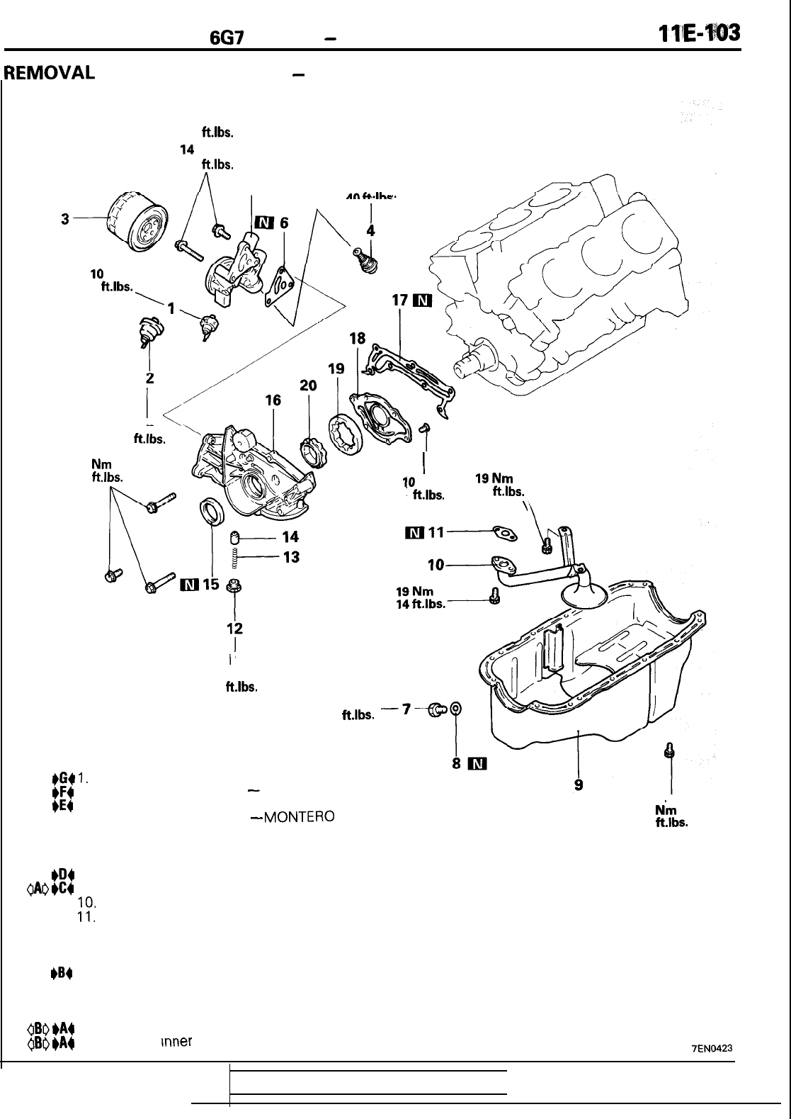
6G7
ENGINE
-
Oil Pan and Oil Pump
{EMOVAL
AND INSTALLATION
-
MONTERO and TRUCK
11!Emw3
Bolt with head mark “4” 24 Nm
17
ft.lbs.
Bolt with head mark “7”
14
Nm
10
ft.lbs.
10
Nm
7
ft.lbs.
\
m
5
55 Nm
in&
Ihc
I<
55 Nm
40
ft.lbs.
14
Nm
11
ft.lbs.
I
45 Nm
33
ft.lbs.
40 Nm
29
ft.lbs.
Removal steps
#G4
1.
Oil pressure switch
#F4
2. Oil pressure gauge unit
-
MONTERO
+E4
3. Oil filter
4. Oil cooler by-pass valve
-
MONTEBO
5. Oil filter bracket
6. Oil filter bracket gasket
7. Drain plug
#III4
8. Drain plug gasket
(IAI)
eC4
9. Oil pan
10.
Oil screen
Il.
Oil screen gasket
12. Plug
13. Relief spring
14. Relief plunger
)B4
15. Crankshaft oil seal
16. Oil pump case
17. Oil pump gasket
18. Oil pump cover
(IBI)
)A4
19. Oil pump outer rotor
@I)
@A4
20. Oil pump
Inner
rotor
I
10
Nm
19Nm
7
ft.lbs.
14
ft.lbs.
\
6
N’m
4
ft.lbs.
7EN0423
TSB Revision
I

IIE-104
6G7
ENGINE
-
Oil Pan and Oil
Pumn
REMOVAL SERVICE POINT
gA0
OIL PAN REMOVAL
(1)
Knock the special tool deeply between the oil pan and the
cylinder block.
(2)
Hitting the special tool on the side, slide it along the oil pan
to remove it.
~BI)
OUTER ROTOR
/
INNER ROTOR REMOVAL
(1)
Make alignment dots on the outer and inner rotors for
-
reference in reassembly.
INSPECTION
OIL PUMP
(1)
Check the tip clearance.
Standard value: 0.03
-
0.08 mm
(.0012
-
.0031
in.)
(2) Check the side clearance.
Standard value: 0.04
-
0.10 mm
(.0016
-
.0039)
(3) Check the body clearance.
Standard value: 0.10
-
0.18 mm
(.0040
-
.0070)
Limit: 0.35 mm
(.0138)
TSB Revision
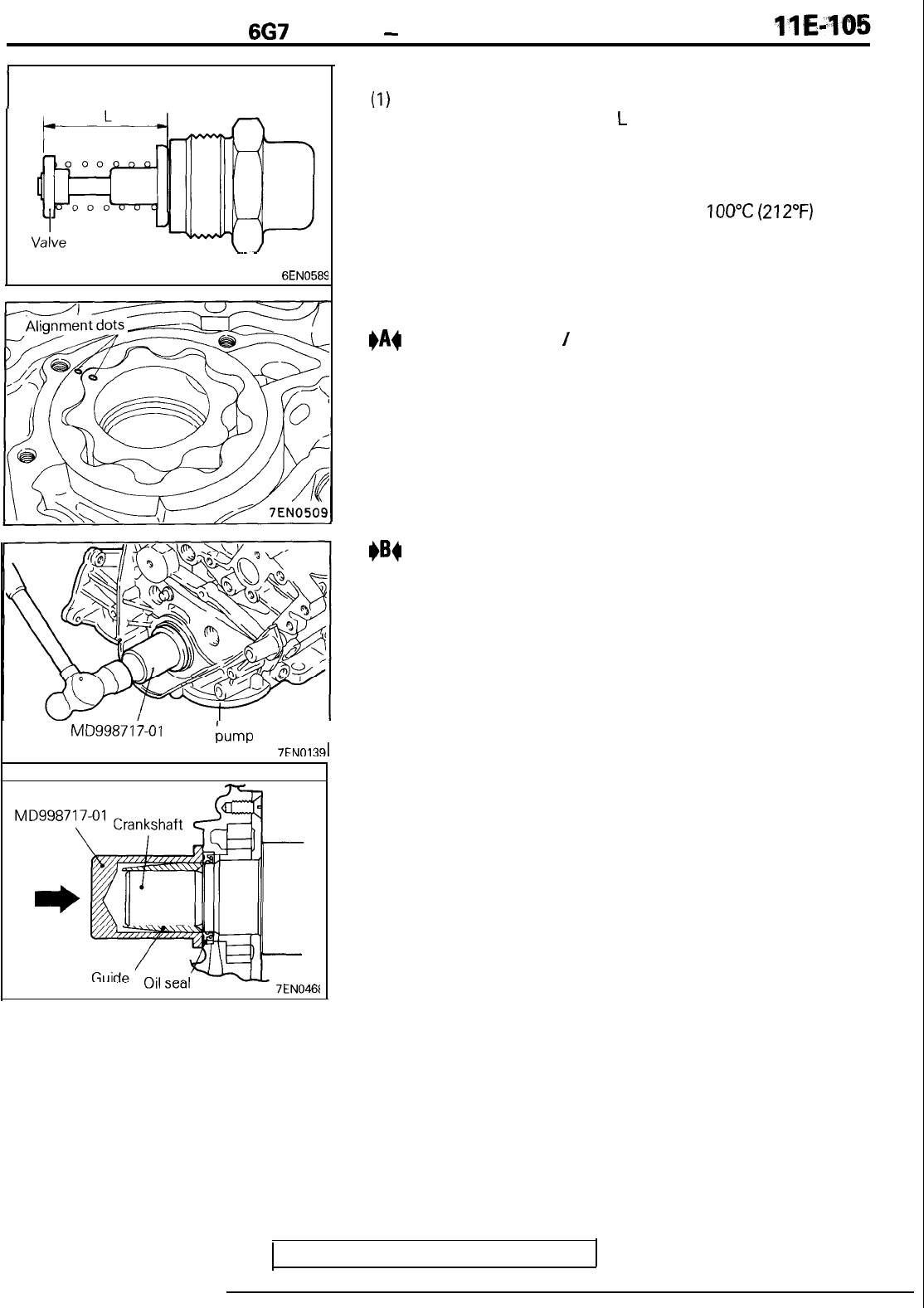
6G7
ENGINE
-
Oil Pan and Oil Pump
6EN0589
MD99871
7-01
Oil bump
I
case
7FNOld
7EN046t
OIL COOLER BYPASS VALVE
(1)
Make sure that the valve moves smoothly.
(2) Ensure that the dimension
L
measures the standard value
under normal temperature and humidity.
Dimension L: 34.5 mm (1.358 in.)
(3) The dimension must be the standard value when measured
after the valve has been dipped in
100°C
(212°F)
oil.
Dimension L: 40 mm (1.57 in.) or more
INSTALLATION SERVICE POINTS
#A$
INNER ROTOR
/
OUTER ROTOR INSTALLATION
(1) Apply engine oil to the rotors. Then, install the rotors
ensuring that the alignment dots made at disassembly are
properly aligned.
I)B4
CRANKSHAFT FRONT OIL SEAL INSTALLATION
(1) Using the special tool, knock the oil seal into the oil pump
case.
NOTE
Knock it as far as it goes.
TSB Revision

IIE-106
6G7
ENGINE
-
Oil Pan and Oil Pump
I)c4
OIL PAN INSTALLATION
(1) Remove all the remaining gasket from the mating surfaces
using a scraper or a wire brush.
(2) Apply a 4 mm
(.I6
in.) diameter bead of sealant to the oil
pan flange.
See “Form In-Place Gasket” in introduction.
Specified sealant:
Mitsubishi Genuine Part No. MD970389 or
equivalent
(3) The oil pan should be installed within 15 minutes after the
application of sealant.
(4) Tighten the flange bolts in the sequence shown in the
illustration.
Bolt
hole
area
(=7
Timing
belt
side
Tightening sequence of flange bolts
(bottom view)
a
Timing
belt side
TSB
Revision

6G7
ENGINE
-
Oil Pan and Oil Pump
1
~@q’@!!
+04
DRAIN PLUG GASKET INSTALLATION
(1) Install the drain plug gasket as illustrated.
m
l
v$ket
\
APPLY
engine oil
6EN059
1
3EN022’
I
+G4
%AEA;T
APPLICATION TO OIL PRESSURE
(1) Coat the threads of the switch with sealant and install the
switch using the special tool.
Specified sealant:
3M
ATD Part No.8660
or equivalent
Caution
1. Keep the end of threaded portion clear of sealant.
2. Avoid an overtightening.
9EN009
4
TSB
Revision
APP~
I)E4
OIL FILTER INSTALLATION
(1) Clean the installation surface of the filter bracket.
(2) Apply engine oil to the O-ring of the oil filter.
(3) Screw the oil filter on until the O-ring contacts the bracket.
Then tighten
3/4
turn.
I)F4
SEALANT APPLICATION TO OIL PRESSURE GAUGE
UNIT
(1) Coat the threads of the gauge unit with sealant and install it
using the special tool.
Specified sealant:
3M
ATD Part No.8660 or equivalent
Caution
1. Keep the end of threaded portion clear of sealant.
2. Avoid an overtightening.

IIE-108
6G7
ENGINE
-
Piston and Connecting Rod
PISTON AND CONNECTING
REMOVAL AND INSTALLATION
ROD
!
4
52
Nm
38
ft.lbs.
Removal steps
1. Nut
GAO
#E4
2. Connecting rod cap
3. Connecting rod bearing (lower)
eD4
4. Piston, connecting rod assembly
5. Connecting rod bearing (upper)
6. Piston rina No.?
1
1
1
7. Piston
rini
No.2
8.
Oil ring
9.
Piston pin
0.
Piston
1.
Connecting
rod
2.
Bolt
7EN0424
TSB Revision

6G7
ENGINE
-
Piston and Connecting Rod
llEJl69
7EN044E
Piston pin setting tool
MIT21
6941
1
3
Q2
e
@J
d/
\
3
cl
II
6O
Q
7EN0426
Press pin
Piston pin
7ENO42
ITss
REMOVAL SERVICE POINTS
OAr)
CONNECTING ROD CAP REMOVAL
(1) Mark the cylinder
numberdon
the side of the connecting rod
big end for correct reassembly.
(2) Keep the removed connecting rods, caps, and
bearings
in
order according to the cylinder number..
060
PISTON PIN REMOVAL
Item No.
Part No.
1
MIT310134
2
MIT310136
3
MIT310137
4 MIT310138
5
MIT310139
6
MIT310140
7
MIT310141
8
MIT310142
9
MIT48143
10
216943
11
10396
Description
Base
Piston Support
Connecting Rod
Guide Pin
Connecting Rod Guide Pin
Connecting Rod Guide Pin
Piston Support
Connecting Rod Guide Pin
Piston Support
Press Pin
Stop Screw
Nut
(1) Remove the stop screw from the base.
.-
(2)
Select the correct piston support for your application. (See
above) Fit the piston support onto the base. Place the base
on the press support blocks.
(3)
Insert
the press pin through the piston pin hole. Select the
correct connecting rod guide pin. (See above.) Thread the
guide pin onto the threaded portion of the press pin.
(4) Position the piston assembly on the piston support in the
press. With the press pin up as shown in the illustration,
insert the guide pin through the hole in the piston and
through the hole in the piston support.
(5) Press the piston pin out of the assembly.
IMPORTANT: To avoid piston damage,
l
The piston support must seat squarely against the
piston.
0
Verify that the piston pin will slide through the hole
in the piston support.
(6) Remove the piston pin from the piston pin.
6

IIE-110
6G7
ENGINE
-
Piston and Connecting Rod
\r/
5EN0066
Push in by piston
Piston ring’
ring gap
INSPECTION
PISTON
(1) Replace the piston if scratches or seizure is evident on its
surfaces (especially the thrust surface). Replace the piston
if it is cracked.
PISTON PIN
(1)
Insert
the piston pin into the piston pin hole with a thumb.
You should feel a slight resistance. Replace the piston pin if
it can be easily inserted or there is an excessive play.
(2) The piston and piston pin must be replaced as an assembly.
PISTON RING
(1) Check the piston ring for damage, excessive wear, and
breakage and replace if defects are evident. If the piston
has been replaced with a new one, the piston rings must
also be replaced with new ones.
(2) Check for clearance between the piston ring and ring
groove. If the limit is exceeded, replace the ring or piston, or
both.
Standard value:
No. 1
DIAMANTE and
3000GT
0.03
-
0.07 mm
(.0012
-
.0026
in.)
MONTERO and TRUCK
0.05
-
0.09 mm
(.0020
-
.0035
in.)
No. 2
0.02
-
0.06 mm
(.OOOS
-
.0024
in.)
Limit: 0.1 mm
(.004
in.)
(3) Insert the piston ring into the cylinder bore. Force the ring
down with a piston, the piston crown being in contact with
the ring, to correctly position it at right angles to the cylinder
wall. Then, measure the end gap with a feeler gauge.
If the ring gap is excessive, replace the piston ring.
Standard value:
No. 1
0.30
-
0.45 mm
(.0118
-
.0177
in.)
No. 2
DIAMANTE and
3000GT
0.45
-
0.60 mm
(.0177
-
.0236
in.)
MONTERO and TRUCK
0.25
-
0.45 mm
(.0098
-
.0177
in.)
Oil
DIAMANTE and
3000GT
0.20
-
0.60 mm
(.0079
-
.0236
in.)
MONTERO and TRUCK
0.20
-
0.70
(.0079
-
.0276
in.)
Limit:
No. 1, No. 2
0.8 mm
(.031
in.)
Oil
1.0 mm
(.039
in.)
TSB Revision
I

6G7
ENGINE
-
Piston and
Connecting
Rod
1
EN0271
Base
Press Pin
F
t
+
/
Piston
SUPPOrt
A
*
scrkw
Pin depth set
7EN042C
3
CRANKSHAFT PIN OIL CLEARANCE
(PLASTIC GAUGE
METHOD)
The crankshaft oil clearance can be measured easily by using a
plastic gauge, as follows:
(1)
Remove oil and grease and any other foreign matters from
the crankshaft pin and the bearing inner surface.
(2) Install the crankshaft.
(3)
Cut the plastic gauge to the same length as the width of the
bearing and place it on the pin in parallel with its axis.
(4) Gently place the crankshaft bearing cap over it and tighten
the bolts to the specified torque.
(5)
Remove the bolts and gently remove the crankshaft bearing
cap.
(6) Measure the width of the smashed plastic gauge at its
widest section by using a scale printed on the plastic gauge
bag.
Standard value: 0.02
-
0.05 mm
(.OOOS
-
.0020
in.)
Limit: 0.1 mm
(.004
in.)
INSTALLATION SERVICE POINTS
+A4
PISTON PIN INSTALLATION
(1)
Thread the stop screw and lock nut assembly into the base.
Fit the correct piston support on the top of the base.
Inset-t
the press pin, threaded end up, into the hole in the piston
support until the press pin touches the stop screw.
(2) Using the graduations on the press pin, adjust the stop
screw to the depth.
Depth: MONTERO and TRUCK 60 mm
DIAMANTE,
3000GT
62 mm
1
TSB
Revision
1

6G7
ENGINE
-
Piston and
Connectinn
Rod
7EN042E
6EN058
1
EN026E
(3) Place the base on the press support blocks.
(4) Slide the piston pin over the threaded end of the press pin,
and thread the correct guide pin up against it.
(5) Coat the piston pin with oil, and with the connecting rod
held in position, slide the guide pin through the piston and
connecting rod.
(6) Press the piston pin through
the.
connecting rod until the
guide pin contacts the stop screw.
(7) Remove the piston assembly from the base. Remove the
guide pin and press pin from the assembly.
IMPORTANT: Due to production tolerance variations, it
is necessary to visually inspect the piston pin depth
after installation to verify that the piston pin is
centered. Adjust if necessary.
#B4
OIL RING INSTALLATION
(1) Fit the oil ring spacer into the piston ring groove.
NOTE
The side rails and spacer may be installed in either direction.
(2) Install the upper side rail
To install the side rail, first fit one end of the rail into the
piston groove, then press the remaining portion into the
position by finger. See illustration.
Use of a ring expander to expand the side rail end gap can
break the side rail, unlike other piston rings.
NOTE
Do not use any piston ring expander when installing the
side rail.
(3) Install the lower side rail in the same procedure as
described in step (2).
(4) Make sure that the side rails move smoothly in either
direction.
TSB
Revision

6G7
ENGINE
-
Piston and Connecting Rod
llE=IA3
\
7ENO452
7EN0369
Upper side
rail
No.1
and spacer gap
6EN0541
MONTERO and TRUCK
bc4
PISTON RING
NO.2
/
PISTON RING
NO.1
INSTALLATION
(1) Using a piston ring expander, fit
No.2
and then
No.1
piston
ring into position.
NOTE
1. Note the difference in shape between
No.1
and
No.2
piston rings.
2.
Install piston rings
No.1
and
No.2
with their side having
marks facing up (on the piston crown side.)
+D4
PISTON AND CONNECTING ROD INSTALLATION
(1) Liberally coat the circumference of the piston, piston ring,
and oil ring with engine oil.
(2) Arrange the piston ring and oil ring gaps (side rail and
spacer) as shown in the illustration.
(3) Rotate the crankshaft so that the crank pin is on the center
of the cylinder bore.
(4) Use suitable thread protectors on the connecting rod bolts
before inserting the piston and connecting rod assembly
into the cylinder block.
Care must be taken not to nick the crank pin.
(5) Using a suitable piston ring compressor tool, install the
piston and connecting rod assembly into the cylinder block.
Caution
Install the piston with the front mark (arrow mark) on
the top of the piston directed towards the engine front
(timing belt side).
NOTE
For MONTERO and TRUCK, two types of pistons, one for
cylinders 1,
3 and 5
and the other for cylinders
2, 4
and
6,
have been used.
Piston with
R: For cylinders 1, 3 and 5
Piston with
L: For cylinders 2, 4 and 6

IIE-114
6G7
ENGINE
-
Piston and Connectinn Rod
Notches
Cylinder No.
/
7EN045:
7EN0454
3
I)E4
CONNECTING ROD CAP INSTALLATION
(1)
Mate the correct bearing cap with the correct connecting
rod by checking with the alignment marks marked during
disassembly. If a new connecting rod is used which has no
alignment mark, position the notches for locking the
bearing on the same side.
(2) Check if the thrust clearance in the connecting rod big end
is correct.
Standard value: 0.10
-
0.25 mm
(.0039
-
.0098
in.)
Limit: 0.4 mm
(.0157
in.)
TSB Revision

6G7
ENGINE
-
Crankshaft, Flywheel and Drive
Plate
1 l’E415
CRANKSHAFT, FLYWHEEL AND DRIVE PLATE
REMOVAL AND INSTALLATION
23
Nm
17 ftlbs.
1
26
I
74
14-
SOHC
79
Nm
57
ft.lbs.
DOHC
-
93
Nm
67
ftlbs.
16
Removal steps
1.
Flywheel
2. Ball bearing
3.
Adaptor plate
4.
Drive
elate
>
For MIT
1
For
4WD
A/T
5. Crankshaft adaptor
1
6. Adaptor plate
7. Drive plate
For FWD
A/T
8. Rear plate
9. Bell housing cover
eF4
IO.
Oil seal case
7k
Nm
54
ft.lbs.
75
Nm
54
ft.lbs.
6
48Nm
35
ft.lbs.
eE4
11. Crankshaft rear oil seal
eD4
12. Bearing cap stay
__
1992
models-Turbo
eC4
13. Bearing cap bolt
eC4
14. Bearing cap
+C4
15. Bearing cap bolt
+C4
16. Bearing
cap
I
1993
models-Turbo
*I34
17. Thrust
beanng
A
+B4
18. Thrust bearing
B
eB4
19. Crankshaft bearing (lower)
20. Crankshaft
#B4
21.
Thrust bearing
B
#B4
22. Thrust bearing A
eB4
23. Crankshaft bearing (upper)
24. Knock sensor
+A4
25. Knock sensor bracket
26. Cylinder block
7EN0514
TSB Revision

6G7
ENGINE
-
Crankshaft, Flywheel and Drive Plate
7ENOl41
INSPECTION
CRANKSHAFT
If the oil clearance exceeds the limit, replace the bearing, and
crankshaft if necessary.
(1) Measure the outside diameter of the journals and the inside
diameter of the crankshaft bearings. If the difference
between them (oil clearance) exceeds the limit, replace the
crankshaft bearing and, if necessary, crankshaft.
Standard value: 0.02
-
0.05 mm
(.0008
-
.0020
in.)
Limit: 0.1 mm
(.004
in.)
Caution
Do not attempt an undersize machining of the crank-
shaft with special
surface
treatment. This crankshaft
can be identified by its dull gray appearance.
CRANKSHAFT JOURNAL OIL CLEARANCE (PLASTIC
GAUGE METHOD)
The crankshaft oil clearance can be measured easily by using a
plastic gauge, as follows:
(1) Remove oil and grease and any other foreign matters from
the crankshaft journal and bearing inner surface.
(2) Install the crankshaft.
(3)
Cut the plastic gauge to the same length as the width of the
bearing and place it on the journal in parallel with its axis.
(4) Gently place the crankshaft bearing cap over it and tighten
the bolts to the specified torque.
(5)
Remove the bolts and gently remove the crankshaft bearing
cap.
(6) Measure the width of the smashed plastic gauge at its
widest section by using a scale printed on the plastic gauge
bag.
CRANKSHAFT REAR OIL SEAL
(1) Check the oil seal lip for wear and damage.
(2) Check rubber for deterioration or hardening.
(3) Check the oil seal case for cracks and damage.
TSB
Revision
I

6G7
ENGINE
-
Crankshaft, Flywheel and Drive Plate
INSPECTION
CYLINDER BLOCK
ll&-1-17
(I\
VisuaUy
check
for scratches, rust, and corrosion. Use
also
a
flaw detecting agent for the check. If defects are evident,
correct, or replace.
(2)
Using a straightedge and feeler gauge, check the block top
surface for
warpage.
Make sure that the surface is free
from gasket chips and other foreign matter.
Standard value: 0.05 mm
(.0020
in.)
Limit: 0.1 mm
(.0039
in.)
(3)
If the distortion is excessive, correct within the allowable
limit or replace.
Grinding limit: 0.2 mm
(.008
in.)
The total thickness of the stock allowed to be
removed from cylinder block and mating cylinder
head is 0.2 mm
(008
in.) at maximum.
Cylinder block height (when new): 210.5 mm (8.29 in.)
-
m
-Thrust
direction
7EN0462
(4) Check the cylinder walls for scratches and seizure. If
defects are evident, correct (rebore to an oversize) or
replace.
(5) Using a cylinder gauge, measure the cylinder bore and
cylindricity. If worn badly, correct by boring the cylinders to
an oversize and replace pistons and piston rings. Measure
at the points shown in the illustration.
Standard value:
Cylinder I.D.: 91.10
-
91.13 mm (3.5866
-
3.5878
in.)
Cylindricity: 0.01
(.0004
in.)
BORING CYLINDER
(1)
Oversize pistons to be used should be determined on the
basis of the largest bore cylinder.
Piston size identification
NOTE
Size mark is stamped on the piston top.
(2) Measure the outside diameter of the piston to be used.
Measure it in the thrust direction as shown.
(3) Based on the measured piston O.D., calculate the boring
finish dimension.
Boring finish dimension
=
Piston O.D. + (clearance
between piston O.D. and cylinder)
-
0.02 mm
(.OOOS
in.)
(honing margin)
TSB Revision

IIE-118
6G7
ENGINE
-
Crankshaft, Flywheel and Drive Plate
(4)
Bore all cylinders to the calculated boring finish dimension.
Caution
To prevent distortion that may result from temperature
rise during honing, bore cylinders in the order of
No.2,
No.4,
No.6,
No.1,
No.3 and
No.5.
(5) Hone to the final finish dimension (piston O.D.
+
clearance
between piston 0-D. and cylinder).
(6) Check the clearance between the piston and cylinder.
Clearance between piston and cylinder:
0.01
-
0.04 mm
(-0004
-
.0016
in.)
NOTE
When boring cylinders, finish all of six cylinders to the same
oversize. Do not bore only one cylinder to an oversize.
INSTALLATION SERVICE POINTS
I)A4
DETONATION SENSOR BRACKET
INSTALLATION
(1) Check that the bracket is in intimate contact with the
cylinder block boss and tighten to specified torque in the
order shown.
1
TSB Revision

6G7
ENGINE
-
Crankshaft, Flywheel and Drive Plate
IfE-m
I)B4
CRANKSHAFT BEARING (UPPER)
/
THRUST BEARING A
/
THRUST BEARING
B
/
CRANKSHAFT BEARING (LOWER) INSTALLATION
(1)
Classify the crankshaft bearings (upper and
lower)
by
whether there is an oil groove or not. Then, assemble as
shown in the illustration.
(2) Assemble the thrust bearings (A and B) on the
No.3
journal
area as shown.
Caution
Install them with the groove side facing outward.
7EN0463
TSB
Revision
Oil groove
Crankshaft
bearing (upper)
No oil groove
Timing belt side
Timing belt side

IIE-120
6G7
ENGINE
-
Crankshaft, Flywheel and Drive Plate
I)c4
BEARING CAP
/
BEARING BOLT INSTALLATION
(1) Attach the bearing cap on the cylinder block as shown in the
illustration.
(2) Tighten the bearing cap bolts to the specified torque in the
sequence shown in the illustration.
(3) Check that the crankshaft rotates smoothly.
Cylinder
(4) Check the end plate. If it exceeds the limit value, replace
the thrust bearing.
Standard value
:
0.05
-
0.25 mm
(.0020
-
.0098
in.)
Limit: 0.3 mm
(.012
in.)
I)Dg
BEARING CAP STAY INSTALLATION
-
DOHC TURBO
(1)
Apply engine oil to the thread and bearing surface of each
bolt.
(2) Temporarily tighten the bolts on the cylinder block side.
(3) Tighten the bolts on the bearing cap side to the specified
(4)
Frr%;:
tighten the bolts on the cylinder block side to the
specified torque.
NOTE
The bearing cap stays A and
B
differ in shape. Install correct
ones on correct sides.
1
TSB Revision

6G7
ENGINE
-
Crankshaft, Flywheel and Drive Plate
IIE-121
7EN046!
7EN0466
M
8990938-01
I
I
MD99871
8-01
Sealing agent
7EN0467
i
-I
I)E4
CRANKSHAFT REAR OIL SEAL INSTALLATION
(1)
Using the special tool, press-fit a new crankshaft rear oil
seal into the oil seal case.
I)F4
OIL SEAL CASE INSTALLATION
(1)
Apply specified sealant to the area shown in the illustration.
Specified sealant:
MITSUBISHI GENUINE Part No. MD970389 or
equivalent
(2) Apply a small amount of engine oil to the entire circuinfer-
ence of the oil seal lip section, and place the oil seal on the
cylinder block.
1
TSB Revision
I
I
I

llE-122
BRACKET
6G7
ENGINE
-
Bracket
REMOVAL AND INSTALLATION
-
DIAMANTE
and
3000GT
42Nm
30
ft.lbs.
2
I
Removal steps
1. Engine support bracket, right
2. Engine support bracket, left
7EN0521
REMOVAL AND INSTALLATION
-
MONTERO and TRUCK
30
ft.lbs.
Removal steps
1.
Roll stopper bracket, front
2. Roll stopper bracket, rear
1
TSB Revision
25
Nm
18
ft.lbs.
