
Keep this Product ID Number and use when contacting Customer Service:
OWNER’S MANUAL
MODEL N° 1306

2
Save this owner’s manual for future reference and in the event that
the manufacturer has to be contacted.
**U.S. and Canada customers ONLY**
IF ASSISTANCE IS NEEDED,
DO NOT CONTACT THE STORE!
CALL OUR CUSTOMER SERVICE DEPARTMENT at
1 (800) 225-3865
HOURS: 7:00 a.m. to 5:00 p.m. Monday through Friday (Mountain Standard Time)
**Call or visit our Web site for Saturday hours**
Lifetime Products, Inc.
**For customers outside the U.S. or Canada, please contact the store for assistance.**
Most injuries are caused by misuse and/or not following instructions. Use caution when using this product.
To ensure safety, do not attempt to assemble this product without reading and
following all instructions carefully. Check the entire box and inside all packing
materials for parts and/or additional instruction material. Before beginning assembly,
identify and inventory all parts and hardware using the parts and hardware lists and
identifi ers in this document. Proper and complete assembly, use and supervision
are essential for proper orientation and to reduce the risk of accident or injury. A
high probability of serious injury exists if this product is not installed, maintained,
and/or operated properly. Failure to comply with any of the warnings in this
instruction manual may result in serious personal injuries such as cuts, broken
bones, nerve damage, paralysis, brain injury, or death. Failure to comply may also
result in property damage. Please heed all warnings and cautions.
• If using a ladder during assembly, use extreme caution.
• Two capable adults are recommended for this operation.
• Check base daily for leakage. Leaks may cause product to fall.
• Assemble the pole sections properly. Failure to do so could cause the pole
sections to separate during play or transport.
SAFETY INSTRUCTIONS
REGISTER YOUR LIFETIME PRODUCT TODAY!
We invite you to read our privacy policy at www.lifetime.com
• Receive exclusive money-saving offers from BuyLifetime.com, our online store, as well
as NEW product notifi cations and special closeout promotions!
• In the unlikely event of a product recall or safety modifi cation, we will notify you.
• Registering your product guarantees you warranty service. If you do not register your
product, your warranty rights will not be diminished. But you will need to provide a sales
receipt to verify your product purchase date before warranty service will be provided.
Maintaining your privacy is our long-standing policy at Lifetime. And you can rest as-
sured that Lifetime will not sell or provide your personal data to other third parties, or
allow them to use your personal data for their own purposes.
BEFORE BEGINNING ASSEMBLY
Keep the hardware bags and their contents separate. If any parts
are missing, call our Customer Service Department.
Identify and inventory all parts and hardware using the parts and
hardware lists and identifi ers in this document.
Test fi t all Bolts by inserting them into their respective holes. If
necessary, carefully scrape away any excess powder coating
buildup from inside the holes. Do not scrape away all of the
powder coating. Bare metal may rust. You may need to pound
some Bolts into place with a hammer or mallet.
INSTRUCTION #1067185 C 10/19/2010

3
Save this owner’s manual for future reference and in the event that
the manufacturer has to be contacted.
**U.S. and Canada customers ONLY**
IF ASSISTANCE IS NEEDED,
DO NOT CONTACT THE STORE!
CALL OUR CUSTOMER SERVICE DEPARTMENT at
1 (800) 225-3865
HOURS: 7:00 a.m. to 5:00 p.m. Monday through Friday (Mountain Standard Time)
**Call or visit our Web site for Saturday hours**
Lifetime Products, Inc.
**For customers outside the U.S. or Canada, please contact the store for assistance.**
Most injuries are caused by misuse and/or not following instructions. Use caution when using this product.
To ensure safety, do not attempt to assemble this product without reading and
following all instructions carefully. Check the entire box and inside all packing
materials for parts and/or additional instruction material. Before beginning assembly,
identify and inventory all parts and hardware using the parts and hardware lists and
identifi ers in this document. Proper and complete assembly, use and supervision
are essential for proper orientation and to reduce the risk of accident or injury. A
high probability of serious injury exists if this product is not installed, maintained,
and/or operated properly. Failure to comply with any of the warnings in this
instruction manual may result in serious personal injuries such as cuts, broken
bones, nerve damage, paralysis, brain injury, or death. Failure to comply may also
result in property damage. Please heed all warnings and cautions.
• If using a ladder during assembly, use extreme caution.
• Two capable adults are recommended for this operation.
• Check base daily for leakage. Leaks may cause product to fall.
• Assemble the pole sections properly. Failure to do so could cause the pole
sections to separate during play or transport.
SAFETY INSTRUCTIONS
REGISTER YOUR LIFETIME PRODUCT TODAY!
We invite you to read our privacy policy at www.lifetime.com
• Receive exclusive money-saving offers from BuyLifetime.com, our online store, as well
as NEW product notifi cations and special closeout promotions!
• In the unlikely event of a product recall or safety modifi cation, we will notify you.
• Registering your product guarantees you warranty service. If you do not register your
product, your warranty rights will not be diminished. But you will need to provide a sales
receipt to verify your product purchase date before warranty service will be provided.
Maintaining your privacy is our long-standing policy at Lifetime. And you can rest as-
sured that Lifetime will not sell or provide your personal data to other third parties, or
allow them to use your personal data for their own purposes.
BEFORE BEGINNING ASSEMBLY
Keep the hardware bags and their contents separate. If any parts
are missing, call our Customer Service Department.
Identify and inventory all parts and hardware using the parts and
hardware lists and identifi ers in this document.
Test fi t all Bolts by inserting them into their respective holes. If
necessary, carefully scrape away any excess powder coating
buildup from inside the holes. Do not scrape away all of the
powder coating. Bare metal may rust. You may need to pound
some Bolts into place with a hammer or mallet.

TOOLS AND PARTS REQUIRED FOR THIS ASSEMBLY
*Two adults required to
complete assembly*
This area is located at the top,
left-hand corner of the page
and indicates which tools
and hardware are needed to
on a page.
Note:
!
Refer to the following areas throughout the instructions
to assist in the assembly process:
bottom, left-hand corner of a step
and indicates that special attention
is needed to perform a particular
part of a step.
the bottom, right-hand corner of a
step and indicate that damage to
occur if the caution or warning is
not heeded.
ASSEMBLY GUIDES
TOOLS AND HARDWARE REQUIRED FOR THIS PAGE
CAUTION
Phillips Screwdriver
(1)
(1)
(1)
Sand
(319 lb)
(1)
Pliers
Rubber Mallet
(1)
(2)
(1)
(1)
(1)
Hammer
(1)

5
TOOLS AND PARTS REQUIRED FOR THIS ASSEMBLY
*Two adults required to
complete assembly*
This area is located at the top,
left-hand corner of the page
and indicates which tools
and hardware are needed to
on a page.
Note:
!
Refer to the following areas throughout the instructions
to assist in the assembly process:
bottom, left-hand corner of a step
and indicates that special attention
is needed to perform a particular
part of a step.
the bottom, right-hand corner of a
step and indicate that damage to
occur if the caution or warning is
not heeded.
ASSEMBLY GUIDES
TOOLS AND HARDWARE REQUIRED FOR THIS PAGE
CAUTION

6
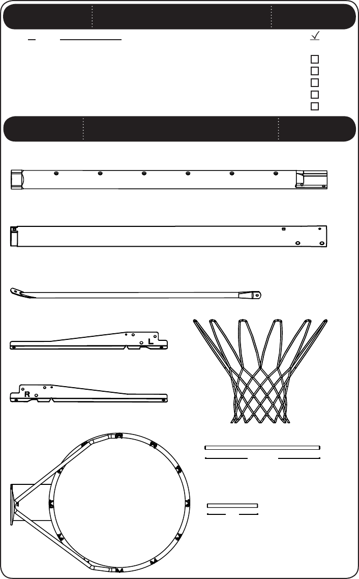
PARTS LIST
ID Item Description Qty
ALH Top Pole 1
ALE Bottom Pole 1
CMZ Slide Collar 1
AJK Right Backboard Bracket 1
AJJ Left Backboard Bracket 1
AJI Backboard 1
ALX Rim 1
AKZ Net 1
AJM Base 1
ALI Pole Brace 2
AMU Wheel 2
AJC 1/2” x 15 3/4” Axle 1
AJE 1/2” x 7” Axle 1
AYU 5/16” Hex Knob 3
CNB Pole Spacer 2
AOX Rim Support Channel 1
AEF Base Plug 2
AMT Warning Sticker (Applied to Middle Pole) 1
HARDWARE LIST
ID Item Description Qty
Pole Assembly Hardware (1066286)
AOL 5/16” x 3 1/4” Carriage Bolt 2
AAN 5/16” Cap Nut 1
ABD 5/16” Washer 1
AYT 5/16” Hex Nut 1
ADS 1/4” x 3/4” Screw (not used) 1
Pole to Base Assembly Hardware (1047792)
AAO 5/16” Nylock Nut 2
ABD 5/16” Washer 4
CNA 5/16” x 4 1/2” Tap Bolt 1
ABN 1/2” x 1/8” Spacer 2
AYT 5/16” Hex Nut 1
BKH 5/16” x 1 1/4” Hex Bolt 2
Backboard to Pole Assembly Hardware (1047754)
APK 3 1/2” U-Bolt 1
APG 5/16” x 3 1/4” Hex Bolt 2
APN 5/16” Flange Lock Nut 2
AAC 5/16” x 1 3/4” Hex Bolt 2
ABK 5/16” Flange Nylock Nut 4
ABD 5/16” Washer 4
ADQ 5/16” x 1” Screw 2
7
Parts shown at 10% of Actual Size
ALH (x1)
Top Pole
ALE (x1)
Bottom Pole
PARTS IDENTIFIER
(x1)
Left Backboard Bracket
(x1)
Right Backboard Bracket
(x1)
1/2” x 15 3/4” Axle
15 ”
3/4
7”
(x1)
1/2” x 7” Axle
ALI (x2)
Pole Brace
43 ”
1/8
*Do not remove Top Pole from Bottom Pole until instructed
HARDWARE LIST
ID Item Description Qty
Cement Anchor Hardware (1047794)
AAF 3/8” Washer 2
CHQ 3/8” x 1” Hex Bolt 2
ABD 5/16” Washer (not used) 2
AQQ 3/8” Concrete Drop-in Anchor 2
CNC 6” Chain 2
AKZ (x1)
Net
ALX (x1)
Rim

8
Parts shown at 5% of Actual Size
PARTS IDENTIFIER
(x1)
Backboard
(x1)
Base
AYU (x3)
5/16” Hex Knob
CNB (x2)
Pole Spacer
AMU (x2)
Wheel
(x2)
Base Plug
Part shown at 25% of Actual Size
CMZ (x1)
Slide Collar
Parts shown Actual Size
AOX (x1)
Rim Support Channel

9
ABN (x2)
1/2” x 1/8” Spacer
HARDWARE IDENTIFIER
Hardware shown at Actual Size
Hardware shown at Actual Size
ADS (x1)
1/4” x 3/4” Screw
(Not used)
AAN (x1)
5/16” Cap Nut
AYT (x1)
5/16” Hex Nut
AOL (x2)
5/16” x 3 1/4” Carriage Bolt
ABD (x1)
5/16” Washer
AAO (x2)
5/16” Nylock Nut
AYT (x1)
5/16” Hex Nut
ABD (x4)
5/16” Washer
CNA (x1)
5/16” x 4 1/2” Tap Bolt
BKH (x2)
5/16” x 1 1/4” Hex Bolt

10
HARDWARE IDENTIFIER
Hardware shown at Actual Size
ADQ (x2)
5/16” x 1” Screw
APK (x1)
3 1/2” U-Bolt
APN (x2)
5/16” Flange Lock Nut
(x2)
5/16” x 3 1/4” Hex Bolt
AAC (x2)
5/16” x 1 3/4” Hex Bolt
ABD (x4)
5/16” Washer
ABK (x4)
5/16” Nylock Flange Nut

11
ABD (x2)
5/16” Washer
(Not used)
HARDWARE IDENTIFIER
Hardware shown at Actual Size
(x2)
3/8” Washer
CHQ (x2)
3/8” x 1” Hex Bolt
AQQ (x2)
3/8” Concrete
Drop-in Anchor
CNC (x2)
6” Chain (not to scale)

12
POLE ASSEMBLY
HARDWARE REQUIRED
PARTS REQUIRED
TOOLS REQUIRED
SEC
1
Parts shown at 10% of Actual Size
Hardware shown at Actual Size
ALH (x1)
Top Pole
ALE (x1)
Bottom Pole
ADS (x1)
1/4” x 3/4” Screw
(Not used)
AAN (x1)
5/16” Cap Nut
AYT (x1)
5/16” Hex Nut
AOL (x2)
5/16” x 3 1/4” Carriage Bolt
ABD (x1)
5/16” Washer
AYU (x1)
5/16” Hex Knob
Part shown at 25% of Actual Size
43 ”
1/8
*Do not remove Top Pole from Bottom Pole until instructed

13
TOOLS AND HARDWARE REQUIRED FOR THIS PAGE
TOOLS AND HARDWARE REQUIRED FOR THIS PAGE
Slide the Top Pole (ALH) far enough out of the Bottom Pole (ALE) so that it
does not obstruct the holes at the bottom of the Bottom Pole. Then
attach the hardware indicated in the location shown.
SEC
1.2
1/2”
AAN (x1)
AOL (x1)
ABD (x1)
Do not overtighten the Cap Nut. If the end of
the Bolt breaks through the plastic cap, call our
Customer Service Department. Exposed threads
on the end of the Bolt may cause serious injuries.
ALH
ALE
AOL
ABD
AAN
While the Top Pole (ALH) is still inside the Bottom Pole (ALE), pull the
plastic off the Top Pole. It may be necessary to loosen the Poles
before pulling out the plastic.
SEC
1.1
Note: Make sure the crimped side of the Top Pole is on the same
side as the Warning Sticker (AMT) on the Bottom Pole.
!
ALH
Sticker
ALE

TOOLS AND HARDWARE REQUIRED FOR THIS PAGE
TOOLS AND HARDWARE REQUIRED FOR THIS PAGE
Slide the Top Pole (ALH) far enough out of the Bottom Pole (ALE) so that it
does not obstruct the holes at the bottom of the Bottom Pole. Then
attach the hardware indicated in the location shown.
SEC
1.2
1/2”
AAN (x1)
AOL (x1)
ABD (x1)
Do not overtighten the Cap Nut. If the end of
the Bolt breaks through the plastic cap, call our
Customer Service Department. Exposed threads
on the end of the Bolt may cause serious injuries.
ALH
ALE
AOL
ABD
AAN
While the Top Pole (ALH) is still inside the Bottom Pole (ALE), pull the
plastic off the Top Pole. It may be necessary to loosen the Poles
before pulling out the plastic.
SEC
1.1
Note: Make sure the crimped side of the Top Pole is on the same
side as the Warning Sticker (AMT) on the Bottom Pole.
!
ALH
Sticker
ALE

15
TOOLS AND HARDWARE REQUIRED FOR THIS PAGE
Insert a 5/16” Hex Nut (AYT) into the 5/16” Hex Knob (AYU) as shown. It may be
necessary to use the to place the Nut in the
Knob. Then position the Top Pole (ALH) at its lowest height and attach the
Knob to the Top Pole and Bottom Pole (ALE) with the hardware shown.
SEC
1.3
AYT (x1)
AOL (x1)
ALH
ALE
AYU
AYU
AYT
AOL

16
POLE TO BASE ASSEMBLY
HARDWARE REQUIRED
SEC
2
Hardware shown at Actual Size
ABN (x2)
1/2” x 1/8” Spacer
BKH (x2)
5/16” x 1 1/4” Hex Bolt
AAO (x2)
5/16” Nylock Nut
ABD (x4)
5/16” Washer
CNA (x1)
5/16” x 4 1/2” Tap Bolt
AYT (x1)
5/16” Hex Nut
(not actual size)

17
TOOLS AND HARDWARE REQUIRED FOR THIS PAGE
ALI
BKH
ABD
ABD
AAO
BKH (x2)
ABD (x4)
ABN (x2)
AAO (x2)
Attach the fl attened end of the Pole Brace (ALI) to the with
the hardware shown. Only fi nger tighten the hardware.
SEC
2.1
Note: Repeat this step to install the other Pole Brace to
the other side of the Base.
!
Slide the through the holes at the end of the Bottom
Pole (ALE) as shown. Slide the through the second set of
holes at the end of the Bottom Pole as shown. Then slide two Pole Spacers
(CNB) over the Axles as indicated. Place the and 1/2” x 1/8”
Spacers (ABN) onto the 1/2” x 15 3/4” Axle.
SEC
2.2
ABN
ABN
AMU
AMU
ALE
(x1)
Base
ALI (x2)
Pole Brace
(x1)
1/2” x 15 3/4” Axle
AMU (x2)
Wheel
15 ”
3/4
7”
(x1)
1/2” x 7” Axle
Parts shown at 10% of Actual Size
Part shown at 25% of Actual Size
PARTS REQUIRED
TOOLS REQUIRED
Part shown at 5% of Actual Size
CNB
CNB
Finger Tighten All Hardware
Parts shown at Actual Size
CNB (x2)
Pole Spacer
AYU (x2)
5/16” Hex Knob
POLE TO BASE ASSEMBLY
SEC
2

18
TOOLS AND HARDWARE REQUIRED FOR THIS PAGE
ALI
BKH
ABD
ABD
AAO
BKH (x2)
ABD (x4)
ABN (x2)
AAO (x2)
Attach the fl attened end of the Pole Brace (ALI) to the with
the hardware shown. Only fi nger tighten the hardware.
SEC
2.1
Note: Repeat this step to install the other Pole Brace to
the other side of the Base.
!
Slide the through the holes at the end of the Bottom
Pole (ALE) as shown. Slide the through the second set of
holes at the end of the Bottom Pole as shown. Then slide two Pole Spacers
(CNB) over the Axles as indicated. Place the and 1/2” x 1/8”
Spacers (ABN) onto the 1/2” x 15 3/4” Axle.
SEC
2.2
ABN
ABN
AMU
AMU
ALE
(x1)
Base
ALI (x2)
Pole Brace
(x1)
1/2” x 15 3/4” Axle
AMU (x2)
Wheel
15 ”
3/4
7”
(x1)
1/2” x 7” Axle
Parts shown at 10% of Actual Size
Part shown at 25% of Actual Size
PARTS REQUIRED
TOOLS REQUIRED
Part shown at 5% of Actual Size
CNB
CNB
Finger Tighten All Hardware
Parts shown at Actual Size
CNB (x2)
Pole Spacer
AYU (x2)
5/16” Hex Knob
POLE TO BASE ASSEMBLY
SEC
2

19
TOOLS AND HARDWARE REQUIRED FOR THIS PAGE
TOOLS AND HARDWARE REQUIRED FOR THIS PAGE
Place the Pole assembly on the ground with the crimped end of the
Top Pole (ALH) facing down. Position the under the
bottom slots of the as shown, and step onto the Base so the
Axle snaps into the slots. Then rotate the Pole assembly upward so that
the snaps into the upper slots of the Base as shown.
SEC
2.3
CNA (x1)
Snap the Slide Collar (CMZ) onto the Bottom Pole (ALE).
SEC
AYT (x1)
(not actual size)
Attach the Pole Braces (ALI) to the Bottom Pole (ALE) by securing the
5/16” Hex Knobs (AYU) through the Slide Collar (CMZ) using the hardware
shown.
SEC
2.5
Note: Tip the system forward so the Pole rests on the ground. Do not stand
the system up until it is fi lled with either sand or water later in the assembly.
!
CMZ
CMZ
ALE
ALI
ALI
ALE
AYU
AYU
CNA
AYT

20
TOOLS AND HARDWARE REQUIRED FOR THIS PAGE
TOOLS AND HARDWARE REQUIRED FOR THIS PAGE
Place the Pole assembly on the ground with the crimped end of the
Top Pole (ALH) facing down. Position the under the
bottom slots of the as shown, and step onto the Base so the
Axle snaps into the slots. Then rotate the Pole assembly upward so that
the snaps into the upper slots of the Base as shown.
SEC
2.3
CNA (x1)
Snap the Slide Collar (CMZ) onto the Bottom Pole (ALE).
SEC
AYT (x1)
(not actual size)
Attach the Pole Braces (ALI) to the Bottom Pole (ALE) by securing the
5/16” Hex Knobs (AYU) through the Slide Collar (CMZ) using the hardware
shown.
SEC
2.5
Note: Tip the system forward so the Pole rests on the ground. Do not stand
the system up until it is fi lled with either sand or water later in the assembly.
!
CMZ
CMZ
ALE
ALI
ALI
ALE
AYU
AYU
CNA
AYT

21
BACKBOARD TO POLE ASSEMBLY
SEC
3
Hardware shown at Actual Size
HARDWARE REQUIRED
(x2)
5/16” x 3 1/4” Hex Bolt
AAC (x2)
5/16” x 1 3/4” Hex Bolt
ABD (x4)
5/16” Washer
ADQ (x2)
5/16” x 1” Screw
APK (x1)
3 1/2” U-Bolt
ABK (x4)
5/16” Nylock Flange Nut
APN (x2)
5/16” Flange Lock Nut

22
TOOLS AND HARDWARE REQUIRED FOR THIS PAGE
Slide the 3 1/2” U-Bolt (APK) through the
. The U-Bolt must rest in the notches of the Backboard Brackets as
shown.
Secure the to the Top Pole (ALH)
with the hardware shown.
SEC
3.1
SEC
3.2
1/2” (x2)
APK
APK
Notch
APK (x1)
(x2)
APN (x2)
(Not actual size)
APN
APN
ALH
BACKBOARD TO POLE ASSEMBLY
SEC
3
PARTS REQUIRED
ALX (x1)
Rim
Parts shown at 10% of Actual Size
Part shown at 5% of Actual Size
(x2)
TOOLS REQUIRED
(x1)
Backboard
(x1)
Left Backboard Bracket
(x1)
Right Backboard Bracket
AOX (x1)
Rim Support Channel
Part shown at 25% of Actual Size

23
TOOLS AND HARDWARE REQUIRED FOR THIS PAGE
Slide the 3 1/2” U-Bolt (APK) through the
. The U-Bolt must rest in the notches of the Backboard Brackets as
shown.
Secure the to the Top Pole (ALH)
with the hardware shown.
SEC
3.1
SEC
3.2
1/2” (x2)
APK
APK
Notch
APK (x1)
(x2)
APN (x2)
(Not actual size)
APN
APN
ALH
BACKBOARD TO POLE ASSEMBLY
SEC
3
PARTS REQUIRED
ALX (x1)
Rim
Parts shown at 10% of Actual Size
Part shown at 5% of Actual Size
(x2)
TOOLS REQUIRED
(x1)
Backboard
(x1)
Left Backboard Bracket
(x1)
Right Backboard Bracket
AOX (x1)
Rim Support Channel
Part shown at 25% of Actual Size

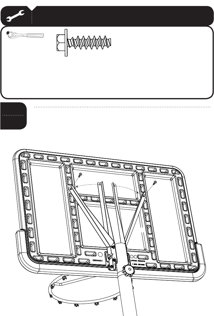
TOOLS AND HARDWARE REQUIRED FOR THIS PAGE
TOOLS AND HARDWARE REQUIRED FOR THIS PAGE
Bend the outward by hand
and position the holes in the Backboard Brackets over the holes in
the . Then securely fasten the Backboard Brackets to
the Backboard with the hardware shown.
SEC
1/2” (x2)
Attach the Rim (ALX) and to the Pole assembly by placing the
Rim Support Channel (AOX) in the recess on the underside of the Backboard
with the fl at side placed against the Backboard. Insert the 3 1/2” U-Bolt
(APK) through the top holes of the Backboard and the Rim, and secure the
U-Bolt with and .
SEC
3.3
Then insert the with
through the bottom holes of the Rim and Backboard and through
the Rim Support Channel and Backboard Brackets, and secure with
the
AAC (x2)
ABD (x4)
ABK (x4)
AOX
AAC
AAC
ABK
ABK
ABD
ABK
ABK
APK
ALX
ABD
ADQ (x2)
3/8”
ADQ
ADQ
25
TOOLS AND HARDWARE REQUIRED FOR THIS PAGE
TOOLS AND HARDWARE REQUIRED FOR THIS PAGE
Bend the outward by hand
and position the holes in the Backboard Brackets over the holes in
the . Then securely fasten the Backboard Brackets to
the Backboard with the hardware shown.
SEC
1/2” (x2)
Attach the Rim (ALX) and to the Pole assembly by placing the
Rim Support Channel (AOX) in the recess on the underside of the Backboard
with the fl at side placed against the Backboard. Insert the 3 1/2” U-Bolt
(APK) through the top holes of the Backboard and the Rim, and secure the
U-Bolt with and .
SEC
3.3
Then insert the with
through the bottom holes of the Rim and Backboard and through
the Rim Support Channel and Backboard Brackets, and secure with
the
AAC (x2)
ABD (x4)
ABK (x4)
AOX
AAC
AAC
ABK
ABK
ABD
ABK
ABK
APK
ALX
ABD
ADQ (x2)
3/8”
ADQ
ADQ

26
HARDWARE REQUIRED
PARTS REQUIRED
TOOLS REQUIRED
SEC
Part shown at 10% of Actual Size
AKZ (x1)
Net
(x2)
Base Plug
Sand
(319 lb)
Part shown at Actual Size
ABD (x2)
5/16” Washer (not used)
(x2)
3/8” Washer
CHQ (x2)
3/8” x 1” Hex Bolt
AQQ (x2)
3/8” Concrete Drop-in Anchor
CNC (x2)
6” Chain (not to scale)
Hardware shown at of Actual Size
Hammer

27
TOOLS AND HARDWARE REQUIRED FOR THIS PAGE
TOOLS AND HARDWARE REQUIRED FOR THIS PAGE
SEC
a. Insert a into the in the hole closest to the Pole.
b. Fill the Base with cold water through the hole furthest from the Pole
until the water is just below the hole.
c. Using two adults, stand the Base up on a fl at
surface and fi nish fi lling the Base with water.
d. Add one tablespoon of chlorine bleach to the
water to prevent algae formation.
e. Insert the other Base Plug into the
hole furthest from the Pole.
(319 lb)
SEC
(319 lb of sand required)
a. Insert a into the in the hole closest to the Pole.
b. Using a funnel, fi ll the Base with sand through the hole furthest from
the Pole until the sand is just below the hole.
c. Using two adults, stand the Base up on a fl at surface and fi nish fi lling
the Base with sand.
d. Insert the other Base Plug into the hole furthest from the Pole.
For safety reasons, we recommend that sand be used
instead of water to fi ll the Base. If a leak develops, water
could run out unnoticed, allowing the system to fall over,
resulting in serious personal injuries, or property damage.
If using Water, check the Base carefully for leaks. If a
leak is found, lay the system down on the ground and
call Customer Service. Do not use, stand up, or play on
a leaking system.

28
TOOLS AND HARDWARE REQUIRED FOR THIS PAGE
TOOLS AND HARDWARE REQUIRED FOR THIS PAGE
SEC
a. Insert a into the in the hole closest to the Pole.
b. Fill the Base with cold water through the hole furthest from the Pole
until the water is just below the hole.
c. Using two adults, stand the Base up on a fl at
surface and fi nish fi lling the Base with water.
d. Add one tablespoon of chlorine bleach to the
water to prevent algae formation.
e. Insert the other Base Plug into the
hole furthest from the Pole.
(319 lb)
SEC
(319 lb of sand required)
a. Insert a into the in the hole closest to the Pole.
b. Using a funnel, fi ll the Base with sand through the hole furthest from
the Pole until the sand is just below the hole.
c. Using two adults, stand the Base up on a fl at surface and fi nish fi lling
the Base with sand.
d. Insert the other Base Plug into the hole furthest from the Pole.
For safety reasons, we recommend that sand be used
instead of water to fi ll the Base. If a leak develops, water
could run out unnoticed, allowing the system to fall over,
resulting in serious personal injuries, or property damage.
If using Water, check the Base carefully for leaks. If a
leak is found, lay the system down on the ground and
call Customer Service. Do not use, stand up, or play on
a leaking system.

29
TOOLS AND HARDWARE REQUIRED FOR THIS PAGE
TOOLS AND HARDWARE REQUIRED FOR THIS PAGE
SEC
ALX
AKZ
Attach Net (AKZ) to the Rim (ALX).
Note: If a replacement Net is needed, please call our Customer Service Department.
Our Nets are shorter than average to reduce the risk of entanglement.
!
SEC
Remove the and the from the
left Pole Brace assembly. Slide the 6” Chain (CNC) onto the
Hex Bolt (BKH) and reattach the hardware as illustrated. Repeat this step
. Tighten the hardware.
1/2” (x2)
CNC (x2)
(not to scale)
BKH
AAO
ABD
CNC

30
TOOLS AND HARDWARE REQUIRED FOR THIS PAGE
TOOLS AND HARDWARE REQUIRED FOR THIS PAGE
SEC
ALX
AKZ
Attach Net (AKZ) to the Rim (ALX).
Note: If a replacement Net is needed, please call our Customer Service Department.
Our Nets are shorter than average to reduce the risk of entanglement.
!
SEC
Remove the and the from the
left Pole Brace assembly. Slide the 6” Chain (CNC) onto the
Hex Bolt (BKH) and reattach the hardware as illustrated. Repeat this step
. Tighten the hardware.
1/2” (x2)
CNC (x2)
(not to scale)
BKH
AAO
ABD
CNC

31
TOOLS AND HARDWARE REQUIRED FOR THIS PAGE
The basketball system may be adjusted from 7 1/2 feet to 10 feet.
ONLY ADULTS SHOULD ADJUST THE HEIGHT OF THE SYSTEM.
To Raise or Lower the Hoop:
a. Using at least two adults, tip the system forward and rest the Rim on a non-
scratching surface. Do not scrape the powder coating off the Rim while adjusting
the system, or you could void the product warranty and cause rusting.
b. With one person holding the system at all times, remove the Adjustment Knob
and the Carriage Bolt. Adjust the system to the desired height and replace the
Bolt and Knob.
c. Make sure the Adjustment Knob is secure
before standing the system back up to
playing position
OPERATION OF HEIGHT ADJUSTMENT SYSTEM
The system must only be moved by people capable of
handling its weight. Children should not be allowed to move the system.
CAUTION: The system must only be moved on its Wheels. Sliding the
Base may damage the Base which could result in leakage and the
system tipping over.
MOVING THE SYSTEM
a. Adjust the system to its lowest position.
b. Stand in front of the system and pull on the Pole until the unit is balanced on
its Wheels.
c. Move the system to the desired location and carefully set the Base down.
SEC
Pull out the end links of the Chains (CNC) so they are away from the sides
of the Base. Mark the location of the last links in the Chain and drill a
hole 13 mm (1/2 inch) in diameter and 39 mm (1 1/2 inches) deep in
the cement in each spot. Place the Cement Anchors (AAQ) in the drilled
holes and use a 5/16” hex bolt and a hammer to tap down the anchor
tab located inside each Anchor. Tap with force at least fi ve or six times
until the sides of the Anchor begin to fl are. Slide a 3/8” x 1” Hex Bolt (CHQ)
through a and through the end link of the Chain. Secure
the Bolts into the Cement Anchors. Repeat for the other side.
With the Base in the desired location, pull out the end links of the Chains (CNC)
so they are away from the sides of the Base. Mark the location of the last links
in the Chain and drill a hole 13 mm (1/2 inch) in diameter and 39 mm (1 1/2
inches) deep in the cement in each spot.
b. Place the Cement Anchors (AD) in the drilled holes and use a 5/16” hex bolt
and a hammer to tap down the anchor tab located inside each Anchor. Tap with
force at least fi ve or six times until the sides of the Anchor begin to fl are.
c. Slide a 3/8” x 1” Hex Bolt (CHQ) through a 3/8” Flat Washer (AAF) and through
the end links of each Chain (CNC).
d. Secure the 3/8” x 1” Hex Bolts (AB) into the Cement Anchors.
To prevent the Base from being punctured, install the cement anchors in a way that will not
permit them to come in contact with the Base. The hardware used with the cement anchor could
puncture the Base, resulting in leakage, which could cause the system to tip over, potentially
resulting in serious personal injuries. Do not attempt to use the portable unit without fi rst fi lling
the Base with weight and securing the cement anchors. The system may fall over without being
secured to the ground and could cause serious personal injuries.
WARNING
Note: Using the Cement Anchors cannot replace fi lling the Base with sand or water.
The Base must be fi lled and secured with the Cement Anchors. Both are necessary
for a secure and stable system.
!
(x2)
CHQ (x2)
AQQ (x2)
To prevent the Base from being punctured, install the
cement anchors in a way that will not permit them to
come in contact with the Base. The hardware used with
the cement anchor could puncture the Base, resulting
in leakage, which could cause the system to tip over,
potentially resulting in serious personal injuries. Do not
attempt to use the portable unit without fi rst fi lling the
Base with weight and securing the cement anchors. The
system may fall over without being secured to the ground
and could cause serious personal injuries.
CHQ
AQQ

32
NOTES

33
NOTES

DAÑOS A LA PROPIEDAD.
Le propriétaire doit s’assurer que tous les joueurs connaissent et appliquent
les règles suivantes afi n d’utiliser l’équipement en toute sécurité.
El propietario del sistema debe asegurarse de que todos los jugadores
conozcan y respeten estas reglas para que el sistema se use en forma
segura.
Owners must ensure that all players know and follow these rules for safe
operation of the system.
• Only hang from the rim briefl y to regain balance or avoid injuring others. Release
the rim as soon as safely possible.
• During play, especially when performing dunk type activities, keep player’s face
away from the backboard, rim, and net. Serious injury could occur if teeth/face
come in contact with the backboard, rim, or net. Player should wear a mouth
guard during play.
• Do not slide, climb, or play on base or pole.
• Completely fi ll base according to manufacturer’s instructions. Never leave the
unit standing in an upright position without fi rst fi lling the base with weight or
the system will tip quickly causing serious personal injury.
• When adjusting height or moving system, keep hands and fi ngers away from
moving parts.
• Do not allow children to move or adjust system.
• Do not wear jewelry (rings, watches, necklaces, etc.) during play. Objects may
entangle in net.
• Keep organic material away from pole base. Grass, litter, etc. could cause
corrosion and/or deterioration.
• Surface beneath the base must be smooth and free of gravel or other objects.
• Cuélguese del aro sólo en forma breve, para recuperar el equilibrio o evitar
lesionar a otros jugadores. Suéltese del aro lo más pronto que pueda hacerlo
con seguridad.
• Durante el juego, especialmente al embocar violentamente de alto, la cara
de los jugadores debe mantenerse alejada del tablero, el aro y la red. Pueden
producirse lesiones graves si los dientes o la cara entran en contacto con el
tablero, el aro o la red. Los jugadores deben usar un protector bucal durante
el juego.
• No se deslice, no trepe ni juegue sobre la base o el poste.
• Llene la base completamente siguiendo las instrucciones del fabricante.
Nunca deje la unidad en posición de uso sin haber llenado previamente la base
con material de contrapeso, pues el sistema podría tumbarse rápidamente y
causar graves lesiones personales.
• Mantenga las manos y los dedos alejados de las piezas movibles cuando
regule la altura o desplace el sistema.
• No deje que los niños regulen ni desplacen el sistema.
• No use joyas (anillos, relojes, collares o gargantillas, etc.) durante el juego.
Estos objetos pueden engancharse en la red.
• La superfi cie donde se coloque la base debe estar lisa y desprovista de
piedras, grava u otros objetos. Las perforaciones pueden originar pérdidas, y
éstas pueden hacer que el sistema se tumbe.
• No permita que la base del poste entre en contacto con materiales
orgánicos. El pasto, los desechos animales, etc., pueden causar corrosión y/o
deterioros.
• Controle el poste y todas las piezas metálicas una vez al mes en busca de
signos visibles de corrosión (oxidación, picaduras, escamado). Elimine todo
rastro de óxido y vuelva a pintar con esmalte para exteriores. Si el óxido ha
penetrado cualquier pieza de acero, reemplace esa pieza de inmediato.
• Inspeccione el sistema antes de cada uso para verifi car que esté
adecuadamente contrapesado, que los elementos de fi jación no estén fl ojos,
que no haya desgaste excesivo, inestabilidad ni signos de corrosión. Si
encuentra irregularidades, repárelas antes de usar el sistema.
Nunca juegue con un equipo dañado.
• No use el sistema en presencia de vientos fuertes o condiciones climáticas
adversas, ya que puede tumbarse. Coloque la unidad en su posición de
almacenamiento y/o en una zona a resguardo del viento, lejos de propiedades
personales que puedan dañarse si el sistema se cae, y de líneas de suministro
de energía.
• No use el sistema para levantar ningún objeto. El mecanismo está diseñado
para elevar solamente el peso del tablero con el aro. No cuelgue nada de la
agarradera, el aro, el tablero ni los brazos de elevación, ya que esto puede
dañar el sistema y anular la garantía.
• Ne vous suspendez pas à l’anneau plus que nécessaire pour retrouver votre
équilibre ou éviter de blesser les autres joueurs. Relâchez l’anneau aussitôt que
possible.
• Lors d’un match, particulièrement dans le cas des smashs, le visage du joueur
ne doit pas faire face au panneau, à l’anneau, ni au fi let. Le joueur risque de
graves blessures si ses dents ou son visage entrent en contact avec le panneau,
l’anneau, ou le fi let. Les joueurs doivent toujours porter un protège-dents
lorsqu’ils jouent.
• Ne glissez pas, ne grimpez pas, et ne jouez pas sur la base ou le poteau.
• Remplissez complètement la base selon les instructions du fabricant. Ne
laissez jamais l’unité debout de plein pied sans avoir d’abord rempli la base avec
un poids ou l’équipement pourrait basculer rapidement et causer de graves
blessures.
• Lorsque vous ajustez la hauteur ou lorsque vous déplacez l’équipement,
gardez vos mains et doigts loin des pièces mobiles.
• Ne permettez pas aux enfants de déplacer ou d’ajuster l’équipement.
• Ne portez pas de bijoux (bagues, montres, colliers, etc.) lorsque vous jouez.
Ces objets pourraient s’accrocher au fi let.
• La surface sur laquelle est posée la base doit être lisse et sans gravier ou tout
autre objet qui pourrait trouer la base entraînant ainsi une fuite ce qui pourrait
faire basculer l’équipement.
• La base ne doit pas non plus être posée sur aucun type de matière organique.
L’herbe, les déchets, etc. peuvent entraîner la corrosion et la détérioration de
l’équipement.
• Une fois par mois, vérifi ez que le Poteau et toutes les pièces en métal ne
montrent pas de signes de corrosion (rouille, piqûres, écaillage). Enlevez toute la
rouille et repeignez complètement avec une peinture pour extérieur. Si la rouille
a pénétré une des pièces en acier, vous devrez remplacer immédiatement la
pièce en question.
• A chaque fois que vous allez utiliser l’équipement, vérifi ez d’abord l’équilibre,
la possibilité de pièces desserrées ou usées, la stabilité de l’équipement et tout
signe de corrosion ou réparation nécessaire avant utilisation.
• Ne jouez jamais avec un équipement endommagé.
• N’utilisez pas l’équipement lors de fortes rafales de vent ou de mauvais temps.
L’équipement pourrait basculer. Placez l’équipement dans un endroit abrité du
vent ou loin des structures qu’il pourrait endommager s’il basculait et loin des
fi ls électriques.
• N’utilisez pas l’équipement pour lever ou soulever quoique ce soit. Son
mécanisme a été conçu uniquement pour soutenir le poids du panneau et de
l’anneau. N’accrochez rien au manche, à l’anneau, au panneau ni aux leviers
sous peine d’endommager l’équipement et d’annuler la garantie.
#FS16400
10/12/2004
www.lifetime.com
Punctures cause leakage and could cause system to tip over.
• Once a month check pole and all metal parts for signs of corrosion (rust, pitting,
chipping). Completely remove rust and repaint with exterior enamel. If rust has
penetrated any steel part, replace that part immediately.
• Check system before each use for proper ballast, loose hardware, excessive
wear, instability, and signs of corrosion and repair before use.
• Never play on damaged equipment.
• Do not use system during windy or severe weather. System may tip over. Place
system in an area protected from the wind or in an area away from property that
may be damaged if the system falls, and from overhead power lines.
• Do not use the system to lift or hoist anything. The mechanism is designed
to lift only the weight of the backboard and rim. Do not hang anything from
the handle, rim backboard, or lifter arms as this will damage the system and
void the warranty.
WARNING
ADVERTENCIA
AVERTISSEMENT
ENHANCE YOUR LIFETIME
®
PURCHASE BY ADDING
ACCESSORIES OR OTHER GREAT PRODUCTS:
Or call: 1-800-424-3865
To purchase accessories or other Lifetime Products, visit us at:
www.lifetime.com

35
Part #600248E
1. One person must stabilize the backboard, while the other person removes the pole locking knob and bolt.
2. Adjust the pole to desired height, and replace the knob and bolt.
3. Make sure adjustment knob is secure.
ADJUSTING THE SYSTEM
1. Make sure the base is empty before moving.
2. Face the front of the base where the wheels are located
and pull back on the pole until the unit is balanced on its
wheels.
3. Move the unit to the desired location and carefully set
it down.
4. Fill the Base, secure cement anchors and check portable
base for stability before play.
TRANSPORTING THE PORTABLE BASE
FAILURE TO FOLLOW THESE WARNINGS MAY RESULT IN SERIOUS INJURY AND/OR
PROPERTY DAMAGE.
OWNERS MUST ENSURE THAT ALL PLAYERS KNOW AND FOLLOW
THESE RULES FOR SAFE OPERATION OF THE SYSTEM.
www.lifetime.com
1. Do Not allow children to move or adjust the system.
2. Always make sure adjustment knob is securely tightened before play.
3. Make sure cement anchors are installed properly during assembly and that they are secure before play.
4. During play, especially when performing dunk type activities, keep players face away from the backboard, rim
and net. Serious injury could occur if teeth/face come in contact with the backboard, rim or net. Player should wear
mouth guard during play.
5. Only hang from rim briefly to regain balance or avoid injuring others. Release the rim as soon as safely pos-
sible.
6. DO NOT slide, climb or play on base or pole.
7. Before each use, always check that the base is filled according to manufacturer’s instructions. Check for loose
hardware, instability, and signs of corrosion and repair before each use. Check the base for leaks. If a leak exists,
water could run out unnoticed, allowing the unit to fall over. Never play on damaged equipment.
8. Surface beneath the base must be smooth and free of gravel or other objects. Punctures can cause leakage
and could cause system to tip over.
9. During play, do not wear Jewelry (rings, watches, necklaces, etc.). Objects may entangle in net.
10. When moving system, keep hands and fingers away from moving parts.
11. Once a month check pole and all metal parts for rust. Completely remove rust and repaint with exterior
enamel. If rust has penetrated any steel part, replace that part before using system again. Keep water and
organic material away from pole.
12. Never operate or leave the unit standing in an upright position without first filling the base with weight and
securing cement anchors or it may tip over into the pool and cause injuries such as those listed above.
13. Do not use system during windy or severe weather. System may tip over. Place system in an area
protected from the wind or in an area away from property that may be damaged if the system falls.
WARNING

36
UNAVAILABLE OR OBSOLETE.
1. Lifetime basketball systems are warranted to the original purchaser to be free from defects in
material or workmanship for a period of fi ve years from the date of original retail purchase. The word
“defects” is defi ned as imperfections that impair the use of the product. Defects resulting from misuse,
abuse or negligence will void this warranty. This warranty does not cover defects due to improper
installation, alteration or accident. This warranty does not cover damage caused by vandalism, rusting,
“acts of nature” or any other event beyond the control of the manufacturer.
2. This warranty is nontransferable and is expressly limited to the repair or replacement of defective
basketball equipment. If the equipment is defective within the terms of this warranty, Lifetime Products,
Inc. will repair or replace defective parts at no cost to the purchaser. Shipping charges to and from
the factory are not covered and are the responsibility of the purchaser. Labor charges and related
expenses for removal, installation or replacement of the basketball system or its components are not
covered under this warranty.
3. This warranty does not cover scratching or scuffi ng of the product that may result from normal
usage. In addition, defects resulting from intentional damage, negligence, unreasonable use or
hanging from the net or rim will void this warranty.
4. Liability for incidental or consequential damages is excluded to the extent permitted by law. While
every attempt is made to embody the highest degree of safety in all equipment, freedom from injury
cannot be guaranteed. The user assumes all risk of injury resulting from the use of this product. All
merchandise is sold on this condition, and no representative of the company may waive or change
this policy.
5. This product is not intended for institutional or commercial use; Lifetime Products, Inc. does not assume
any liability for such use. Institutional or commercial use will void the warranty.
6. This warranty is expressly in lieu of all other warranties, expressed or implied, including warranties
of merchantability or fi tness for use to the extent permitted by Federal and state law. Neither Lifetime
Products, Inc., nor any representative assumes any other liability in connection with this product.
This warranty gives you specifi c legal rights, and you may also have other rights which vary from
state to state.
Lifetime Products, Inc., PO Box 160010 Clearfi eld, UT 84016-0010, or call (800) 225-3865
M-F 7 a.m. to 5 p.m. MST.
**Call or visit our Web site for Saturday hours**
Please include your dated sales receipt and photographs of damaged parts.
WARRANTY INFORMATION
www.lifetime.com
FAUTE DE NE PAS SUIVRE CES AVERTISSEMENTS,
VOUS RISQUEZ DE CAUSER DES BLESSURES
GRAVES ET/OU DES DOMMAGES À L’ÉQUIPEMENT.
SI NO SE OBEDECEN ESTAS ADVERTENCIAS
PUEDEN PRODUCIRSE GRAVES LESIONES Y/O
DAÑOS A LA PROPIEDAD.
Le propriétaire doit s’assurer que tous les joueurs
connaissent et appliquent les règles suivantes afin
d’utiliser l’équipement en toute sécurité.
WARNING
El propietario del sistema debe asegurarse de que
todos los jugadores conozcan y respeten estas reglas
para que el sistema se use en forma segura.
FAILURE TO FOLLOW THESE WARNINGS MAY
RESULT IN SERIOUS INJURY AND/OR PROPERTY
DAMAGE.
Owners must ensure that all players know and follow
these rules for safe operation of the system.
• Cuélguese del aro sólo en forma breve, para recuperar el
equilibrio o evitar lesionar a otros jugadores. Suéltese del
aro lo más pronto que pueda hacerlo con seguridad.
• Durante el juego, especialmente al embocar violentamente
de alto, la cara de los jugadores debe mantenerse alejada
del tablero, el aro y la red. Pueden producirse lesiones
graves si los dientes o la cara entran en contacto con
el tablero, el aro o la red. Los jugadores deben usar un
protector bucal durante el juego.
• No se deslice, no trepe ni juegue sobre el poste.
• Mantenga las manos y los dedos alejados de las piezas
movibles cuando regule la altura del sistema.
• No deje que los niños regulen el sistema.
• No use joyas (anillos, relojes, collares o gargantillas, etc.)
durante el juego. Estos objetos pueden engancharse en la
red.
• No permita que la base del poste entre en contacto con
materiales orgánicos. El pasto, los desechos animales, etc.,
pueden causar corrosión y/o deterioros.
• Controle el poste y todas las piezas metálicas una vez al
mes en busca de signos visibles de corrosión (oxidación,
picaduras, escamado). Elimine todo rastro de óxido y
vuelva a pintar con esmalte para exteriores. Si el óxido ha
penetrado cualquier pieza de acero, reemplace esa
pieza
de inmediato.
• Inspeccione el sistema antes de cada uso para verificar
que los elementos de fijación no estén flojos, que no haya
desgaste excesivo, inestabilidad ni signos de corrosión.
Si encuentra irregularidades, repárelas antes de usar el
sistema.
• Nunca juegue con un equipo dañado.
• No use el sistema para levantar ningún objeto. El
mecanismo está diseñado para elevar solamente el peso
del tablero con el aro. No cuelgue nada de la agarradera, el
aro, el tablero ni los brazos de elevación, ya que esto puede
dañar el sistema y anular la garantía.
•Ne vous suspendez pas à l’anneau plus que nécessaire
pour retrouver votre équilibre ou éviter de blesser les autres
joueurs. Relâchez l’anneau aussitôt que possible.
• Lors d’un match, particulièrement dans le cas des smashs,
le visage du joueur ne doit pas faire face au panneau, à
l’anneau, ni au filet. Le joueur risque de graves blessures si
ses dents ou son visage entrent en contact avec le panneau,
l’anneau, ou le filet. Les joueurs doivent toujours porter un
protège-dents lorsqu’ils jouent.
• Ne glissez pas, ne grimpez pas, et ne jouez pas sur la base
ou le poteau.
• Lorsque vous ajustez la hauteur ou l’équipement, gardez
vos mains et doigts loin des pièces mobiles.
• N’autorisez pas les enfants à ajuster l’équipement.
• Ne portez pas de bijoux (bagues, montres, colliers, etc.)
lorsque vous jouez. Ces objets pourraient s’accrocher au
filet.
• Gardez la base du poteau libre de toute matière organique.
L’herbe,
les déchets, etc. peuvent la corroder et la
détériorer.
• Une fois par mois, vérifiez que le poteau et toutes les pièces
en métal ne montrent pas de signes de corrosion (rouille,
piqûres, écaillage). Enlevez toute la rouille et repeignez
complètement avec une peinture pour extérieur. Si la rouille
a pénétré une des pièces en acier, vous devrez remplacer
immédiatement la pièce en question.
• A chaque fois que vous allez utiliser l’équipement, vérifiez
d’abord l’équilibre, la possibilité de pièces desserrées ou
usées, la stabilité de l’équipement et tout signe de corrosion
ou réparation nécessaire avant utilisation.
• Ne jouez jamais avec un équipement endommagé.
• N’utilisez pas l’équipement pour lever ou soulever quoique
ce soit. Son mécanisme a été conçu uniquement pour
soutenir le poids du panneau et de l’anneau. N’accrochez
rien au manche, à l’anneau, au panneau ni aux leviers sous
peine d’endommager l’équipement et d’annuler la garantie.
ADVERTENCIA
AVERTISSEMENT
Only hang from the rim briefly to regain balance or avoid
injuring others. Release the rim as soon as safely possible.
During play, especially when performing dunk type activities,
keep player’s face away from the backboard, rim, and net.
Serious injury could occur if teeth/face come in contact with
the backboard, rim, or net. Player should wear a mouth
guard during play.
Do not slide, climb, or play on pole.
When adjusting height or moving system, keep hands and
fingers away from moving parts.
Do not allow children to move or adjust system.
Do not wear jewelry (rings, watches, necklaces, etc.) during
play. Objects may entangle in net.
Keep organic material away from pole base. Grass, litter,
etc. could cause corrosion and/or deterioration.
Once a month check pole and all metal parts for signs of
corrosion (rust, pitting, chipping). Completely remove rust
and repaint with exterior enamel. If rust has penetrated any
steel part, replace that part immediately.
Check system before each use for loose hardware,
excessive wear, instability, and signs of corrosion and repair
before use.
Never play on damaged equipment.
Do not use the system to lift or hoist anything. The
mechanism is designed to lift only the weight of the
backboard and rim. Do not hang anything from the handle,
rim backboard,
or lifter arms as this will damage the system
and void the warranty.
#FS16500
10/12/2004
www.lifetime.com
