
LED Retrofit Kits, TLEDs,
and Lighting Controls:
An Application Guide
Lighting use constitutes about 20%
of the total source electricity con-
sumption in commercial buildings.
The vast majority of lighting in U.S.
commercial buildings is provided by
fluorescent troer ceiling fixtures.
There are currently over 350 million
installed troers using more than 65
million kWh (the annual energy
usage of 6 million U.S. homes).
Retrofitting these fluorescent troers
to light-emitting diode (LED) sources
oers the potential for enormous
energy savings. As of 2015, only 5%
of the troers in use had LED light
sources. At a project level, retrofitting
or replacing fluorescent troers with
LEDs can result in energy savings of
20% to 60% and help agencies meet
energy-eciency goals.
Troer Lighting at a Glance
The term “troffer” is a combination of two different architectural elements: a “trough” and
a “coffer.” A troffer is a rectangular light xture designed to t into a modular dropped ceil-
ing grid. Fluorescent tubes were introduced to the market in 1938, and ceiling troffer x-
tures were soon designed to accommodate standard linear uorescent lamp sizes (T12s,
T8s, and T5s). Troffers are typically available in standard sizes of 1x4-ft, 2x4-ft, and 2x2-ft.
There are hundreds of millions of uorescent-based troffers in use in the United States;
nearly every commercial building has them. Around 2010, LEDs began to gain popularity
for interior lighting, and lighting manufacturers began designing troffer models with integral
LED sources. Most LED troffer luminaires sold today are still designed in the traditional
Have access to
ceiling plenum
and no known
hazards in ceiling?
Will you be in the
space more than
5 years?
yes
no/unknown
Consider a
retrofit kit
Do you want the
lowest first-cost
option?
no
yes
Consider
TLED
Do you want
lighting
controls?
yes
Consider Type C
TLED
Consider a
new fixture
yes
Consider Type A
TLED
no
Consider Type B
TLEDno
Are you looking for
FEMP designated
products?
yes
Is your space
covered by
GSA P100?
yes
yes
Is your space
covered by
DoD’s Unified
Facilities Criteria?
yes
yes
Will you plan for
ballast replacement in the future?
Does the facility understand the
potential shock hazard/risk of line
voltage being provided to the socket?
Are you willing to spend added
time and money to have the fixture
rewired by skilled electricians?
yes
yes
yes
yes
no
yes
no
yes
In a lighting upgrade of the New Carrollton Federal Building in Lanham, Maryland, the
General Services Administration cut energy use by 82% and trimmed an annual lighting
bill from $291,000 to $53,500 by replacing 11,800 fluorescent troers with LED fixtures
and controls. Photo source: GSA.
Figure 1. Determining the best LED troer retrofit option for your facility
LED Troer Retrofit Lighting and Controls
Best Practices
FEDERAL ENERGY MANAGEMENT PROGRAM

1x4-ft, 2x4-ft, and 2x2-ft rectangular troffer
shapes, although that may change for new
buildings as architects and lighting design-
ers realize they are free from the design con-
straints dictated by the size and shape of
linear uorescent troffers. Recognizing the
preponderance of uorescent troffers in
existing buildings, lighting manufacturers
also began to market tubular LED lamps
and LED retrot kits that replace the uo-
rescent light sources in existing troffers to
provide the same light levels with longer
lasting LED solutions that use less energy.
Retrofit Options
This document provides guidance for
retrotting existing uorescent troffer
xtures with LEDs. Information about
lighting controls is also provided.
There are three retrot options:
1. Lamp – Replace the lamp only with
tubular LEDs (TLEDs).
2. Retrot Kit – Replace the uorescent
lamps and other luminaire components
with an LED retrot kit.
3. Luminaire – Replace the entire uores-
cent luminaire, including the housing,
with a new LED luminaire.
Table 1 summarizes pros and cons of
each option, what agencies approve or have
criteria associated with an option’s use, and
an approximate sense of installation time,
energy savings, and rst cost.
Figure 1 (on the previous page) is a
decision tree to guide decision makers in
choosing the best option for their facility.
Reduced-
Wattage
Tubular
Fluorescents*
*This option is included for comparison purposes only.
Retrofit
Option
Installation
Time
First
Cost
Energy
Savings
Fed. Agency
Approved
(as of 2/1/2017)
Option
Pros Cons
Very low cost ($3–$10/lamp). Long life.
May use existing ballast so quick
installation.
Aging ballast may fail soon; may be hard
to find replacement. To add controls to
dim or reduce wattage, you must change
the ballast.
DoD: yes
GSA: yes
FEMP: yes
<5 min 20% ¢
TLEDs
In-Line
Ballast
TLEDs
Use existing ballast and sockets. No
rewiring, no electrician needed. Low
shock risk. Fast. Lowest cost on parts
and labor.
Aging ballast may fail soon; may be hard
to find ballast replacement in the future.
Possible ballast incompatibility. Possible
flicker. High risk of product failure. May
not dim. Least efficient of TLED options.
To add dimming controls, you must
change the ballast.
DoD: yes
GSA: case-by-case
FEMP: no criteria
<5 min 20% $
1
A
Line-Voltage
TLEDs
Does not rely on existing ballast. Greater
energy savings than in-line ballast. Low
cost on parts. Quick installation.
Potentially fatal shock hazard at
installation. Requires electrician.
Requires label. Heavy TLEDs might
cause issues with the lamp holders.
To add controls to dim or reduce wattage,
you must change the ballast.
DoD: no
GSA: case-by-case
FEMP: no criteria
<15 min 30%–50% $$
B
External-
Driver TLEDs
Safer than Type B. External driver
provides better thermal management.
Easier to add controls.
Lower voltage from driver to sockets.
Lower cost than retrofit kits. Most
efficient of the TLED options.
Requires electrician. Requires a label.
Not as efficient as retrofit kits. Heavy
TLEDs might cause issues with the
lamp holders.
DoD: no
GSA: case-by-case
FEMP: no criteria
<15 min 30%–50% $$
C
Retrofit Kits
Uses existing housing but replaces old
lamps, ballasts, and sockets with new
electronics and LED modules for longer
life. Better heat management and lower
failure potential than TLEDs. Higher
efficiency than TLEDs. Can add lighting
controls. Less labor than a new fixture.
Higher parts and labor costs than TLEDs.
Requires electrician.
DoD: yes
GSA: yes
FEMP: no criteria
<15 min 60% $$
2
New
Luminaires
Maximum energy savings. Fixture is
designed to optimize LED source
performance. Maximum potential for
adding lighting controls. Could add
non-lighting controls (carbon dioxide,
heat, etc.) Lowest failure potential;
longest lasting.
Most expensive for parts and labor.
Requires electrician. May require access
above ceiling; potential safety and health
risks. Most time to install. One-for-one
replacement may over-light space and
may require costly redesign for maximum
efficiency.
DoD: yes
GSA: yes
FEMP: yes
>30 min 60% $$$
3
Table 1. Comparison of LED Options for Retrofitting Troers: Pros and Cons, Costs and Benefits
FEDERAL ENERGY MANAGEMENT PROGRAM
2

Tubular LEDs
Tubular LEDs (TLEDs) are LEDs that
match the form factor (diameter, length,
and base) of uorescent tubes so they can
plug into the existing sockets in a uores-
cent troffer. There are three types of
TLEDs:
1. Underwriters Laboratory (UL)
Type A – The TLED uses the
existing uorescent ballast; the
TLED also has an internal driver.
2. UL Type B – The wiring from the
existing ballast is terminated, the sock-
ets are rewired from the branch circuit,
and the TLED operates from line volt-
age supplied directly to the xture; the
TLED has an internal driver.
3. UL Type C – The TLED uses line volt-
age, but electrical connections to the
ballast are terminated and the line volt-
age is connected to an external driver
that powers the TLED.
When considering retrot options, TLEDs
tend to be the least expensive rst-cost
option. Another big advantage of TLEDs
is the time savings. In many cases, the
reectors and louvers or lens remain; the
only part being replaced is the lamp (how-
ever, sometimes the sockets also need to
be replaced). Installing a UL Type A
TLED is as easy as replacing a uorescent
lamp. UL Type B and Type C lamp
replacements take slightly longer because
they require some rewiring, which can
also increase the labor costs as an electri-
cian is required. Figure 2 depicts these
three TLED types, and Table 1 lists pros
and cons of each.
With UL Type A TLEDs, the existing bal-
last stays connected to the sockets,
whereas with Type B and C TLEDs, the
ballast is disconnected. While uorescent
lamps use a ballast to regulate current and
provide voltage to start the lamp, LEDs
use a driver instead; the driver controls the
current and regulates the power. While UL
Type A and Type B TLEDs have an inter-
nal driver, UL Type C TLEDs have an
external driver, which provides better
thermal management and may contribute
to a longer lasting lamp.
Although UL Type A TLEDs may seem
like the simplest retrot option because
you can reuse the ballast, there are sev-
eral things to keep in mind about uores-
cent ballasts and TLEDs:
• The uorescent ballast will limit the
energy efciency of the luminaire. UL
Type A TLEDs are the least
efcient of the TLEDs.
• Ballasts vary and it cannot be assumed
that all ballasts will work with all
TLEDs. Fixture manufacturers supply
different ballasts in the same xture
line to reduce supply chain risks, so
two otherwise identical xtures could
have different ballasts, which could
lead to compatibility issues with some
xtures in a project.
• Aging ballasts are likely to fail before
the TLED fails. As LEDs gain market
share, some ballasts may become
harder to nd. If your ballasts are
older than 5 years, consider UL Type
B or C replacement lamps, retrot kits,
or new luminaires instead.
• As uorescent ballasts age, they may
cause icker in some UL Type A
TLEDs.
• Emer gency lighting might be incom-
patible with some UL Type A TLEDs,
so test the TLEDs if using them in an
emergency lighting system.
UL Type B TLEDs, also sometimes
referred to as line-voltage TLEDs, have the
highest safety risk because they involve
rewiring 120-volt line voltage directly to
the sockets. The installer is required to put
a label on the xture indicating that the x-
ture has been modied, that a potential
shocking hazard exists, and that the lamp
should not be replaced with a uorescent
lamp. Because of the high voltage, the
shock could cause serious injury or death.
The Federal Energy Management Program
(FEMP) has no stated minimum efcacy
requirement for TLEDs, but it does have a
FEMP-designated minimum requirement
for linear uorescent lamps of 98 lumens
per watt (lm/W). (This is measured as bare
lamp, or with the lamp outside of the x-
ture.) So, when considering replacing uo-
rescents with TLEDs, to achieve energy
savings, the TLED should at a minimum
have an efcacy greater than 98 lm/W. The
U.S. Department of Defense’s Unied
Facilities Criteria (DoD UFC) requires that
TLEDs have a minimum efcacy of 100
lm/W (bare lamp). The Design-Lights
Consortium requires that TLEDs have a
minimum efcacy of 110 lm/W, which is a
good rule of thumb to achieve at least 10%
energy savings over the minimum require-
ment for uorescent tubes.
UFC does not have a light output require-
ment for TLEDs, but the DesignLights
Consortium’s requirement of 1,600 lumens
(bare lamp) is a good minimum for TLED
lamp retrots.
TLED UL Type A TLED UL Type B TLED UL Type C
From Branch Circuit (line voltage, 120 or 277 volts)
Internal
Driver
External
Driver
Socket
Existing
Ballast
Lower
Voltage
LEDs
Figure 2. TLEDs can fit into existing sockets. UL Type A TLEDs use the existing driver. UL
Type A and B TLEDs have internal drivers while Type C TLEDs have external drivers.
FEDERAL ENERGY MANAGEMENT PROGRAM
3

Retrofit Kits
Retrot kits cost more than TLEDs but are
generally more efcient and, in some
cases, can be installed almost as quickly as
UL Type B or C Type C TLEDs. Figure 3
shows the components in a uo rescent trof-
fer and the same troffer housing with an
LED retrot kit.
The industry uses the term retrot kit,
while some federal agencies use the term
conversion kit. UFC denes a luminaire
conversion kit as a sys tem that replaces the
lamp and other lumi naire components,
including the ballast and/or the reector,
wiring, and diffusers. According to UFC,
direct replacement of a uores cent or other
lamp with an LED lamp without electri cal
or mechanical changes is not considered to
be a luminaire conversion.
Installation Time Requirements
Although the electrical components (bal-
lasts, sockets, and wiring) of the troffer are
disconnected and, in most cases, removed
with retrot kits, retrot kits allow for the
xture housing to remain in place. Not
having to disconnect the housing from the
ceiling to install a new housing is a signi-
cant time-saving feature of retrot kits. The
space above a xture might have hazard-
ous materials that could require remedia-
tion. As labor costs can easily exceed the
cost of materials, any reduction in labor
time will add to the cost effectiveness of
the upgrade. Some troffer xture designs
Federal LED Troer Lighting Requirements
TheUSDepartmentofEnergy’sFederalEnergyManagementProgram(FEMP)provides
informationaboutenergyecientproductsandpromisingnewenergy-savingtechnolo-
giesthatcanhelpagenciesmeetfederalstandardsFederallawsandrequirementsman-
datethatagenciespurchaseENERGYSTAR-labeledorFEMP-designatedproductsinall
productcategoriescoveredbytheseprogramsENERGYSTARdoesnotcovercommercial
lightingproductsliketroersFEMP-designatedeciencyrequirementscovercertaincom-
mercialandindustriallight-emittingdiode(LED)luminaireproductcategories(seeTable)
TherearenoFEMP-designatedrequirementsfortubularLEDs(TLEDs)andLEDretrofitkits
ForbranchesofthemilitarytheUSDepartmentofDefense(DoD)hassomeadditional
requirementswhichareoutlinedintheUnifiedFacilitiesCriteria(UFC)TheUSGeneral
ServicesAdministration(GSA)establishesdesignstandardsfornewbuildingsandretrofits
initsguideFacilities Standards for the Public Buildings ServicereferredtoasP(See
the“Resources”sectionofthisguideforlinksandadditionalinformation)Tableshowsthe
Federalagencyrequirementsalongwithsomevoluntaryfederalprogramcriteriafornew
andretrofittroeroptions
are more difcult to retrot because the
xture housing is contoured around the
lamps. (See Table 4.) Also, the light distri-
bution may differ after retrot because the
optics are designed for uorescent lamps.
Ecacy
Neither FEMP nor the U.S. General
Services Administration (GSA) have
requirements for retrot kits. UFC requires
that retrot kits be 120 lm/W. For compari-
son, FEMP does have a minimum efcacy
requirement for new LED troffer lumi-
naires of 99 to 103 lm/W, depending on the
conguration, which is quite a bit higher
than its minimum requirement for new u-
orescent luminaires of 55 to 89 lm/W. (See
Table 2 for more on requirements.) UFC
does not have a minimum light output
requirement, but states that “the resulting
system must produce equivalent light lev-
els.” UFC also requires that the kit produce
at least 70% of the initial light for at least
50,000 hours.
FEMP Designated
DoD Unified Facilities
Criteria - UFC 3-530
(June 2016)*
GSA P100 (March 2016)**
Voluntary
DesignLights Consortium
(Version 4.1)
Better Buildings Alliance
Model Technical Specification
for High Efficiency Troffers
(Version 6.0)
NR
100 lm/W
(bare
lamp)
NR
110 lm/W
(bare
lamp)
NA
NR
120
lm/W
NR
100
lm/W
NA
≥99 lm/W (1x4)
≥100 lm/W (2x2)
≥103 lm/W (2x4)
NR
NR
100 lm/W
125 lm/W
≥1,500 lm (1x4)
≥2,000 lm (2x2)
≥3,000 lm (2x4)
Retrofit Kit:
Equivalent light
level; ≥70% of
initial light for
≥50,000 hours
NR
1,500 lm (kit/
luminaire)
1,600 lm (bare lamp)
1,500 lm (1x4)
2,000 lm (2x2)
3,000 lm (2x4)
NR
≤4100 K
≤3500 K
≤5000 K
2200K-
5000K
NR
≤80
≤80
≤80
≤80
Device Efficacy (lumens/Watt)
TLED Retrofit
Kit
New/Replacement
Luminaire
Light Output
(lumens)
Color Characteristics
CCT CRI
CCT = Correlated color temperature; CRI = Color rendering index; K = Kelvin; NA = Not applicable; NR = No requirement
*As of June 2016, DoD UFC allows Type A TLEDs for all military branches.
**TLEDs UL Type A, B, and C are only approved by GSA on a case-by-case basis.
Federal Standard
Table 2. LED Requirements in Federal Programs
Lamp
Ballast
Reflector
Housing
Ceiling
Tile
Lens
LEDs
External Driver
Reflector
Housing
Ceiling
Tile
Lens
Figure 3. Troer Retrofit – before and
after installing the retrofit kit
Fluorescent Troer
LED Troer Retrofit Kit
FEDERAL ENERGY MANAGEMENT PROGRAM
4

Controls
Retrot kits offer greater energy savings
potential from lighting controls than is
possible with TLEDs. The retrot kit
body itself provides a physical location to
mount the sensors to. For small retrots,
retrot kits can interface with stand-alone
wireless controls systems. For large-scale
whole-building retrots, more complex
controls systems can be deployed while
new retrot kit wiring is being installed.
New Luminaires
Replacing the entire xture with new x-
tures is typically the most expensive
option. However, it offers several
advantages. It is likely to provide both the
highest efciency and effectiveness, in
terms of the light source itself and
because the xture components and hous-
ing shape are designed to maximize light
output from an LED light source.
Depending on the model, it is likely to
work most seamlessly with controls and
may come with the controls integrated in
the xture by the manufacturer. It is likely
to be a longer lasting option. If the exist-
ing equipment is in poor condition, total
xture replacement may be the only
option. The biggest disadvantage is the
need to remove the housing from the ceil-
ing, which may require access above the
ceiling and potential health and safety
risks, as well as increased product and
labor costs.
Factors to Consider
Selecting the best option for an installa-
tion depends on several factors: the cur-
rent condition of the ballast and luminaire
components, desired photometric proper-
ties of the upgraded lighting system,
accessibility of the ceiling plenum, pur-
chase and installation budget, and ongo-
ing economic goals for the upgrade.
Product quality and performance vary
widely within each upgrade option and
individual products should be evaluated
on their own merits. Here is some guid-
ance on the various factors to consider
when deciding among the options for an
upgrade to LED troffer lighting.
Existing Condition of
Luminaires
Consider the condition of the luminaire
when deciding whether to relamp, retrot,
or replace. Damaged housings, cracked or
discolored lenses, scratches, yellowing of
the reector, peeling paint, and rusted or
broken components can all contribute to
the decision to replace or retrot the lumi-
naire rather than just replacing the lamps.
If the ballast is older than 5 years, a UL
Type A TLED lamp-only replacement is
not recommended. Luminaire design can
also make replacing the lamps challeng-
ing (see Table 4).
Equipment Purchase Costs
When considering purchase price, LED
replacement lamps are usually the lowest
cost option, retrot kits are higher, and
new LED luminaires are the highest cost.
Compare purchase and installation prices
when considering retrot kits versus new
luminaires; retrot kits are not always a
bargain.
Installation Labor Costs
TLED replacement lamps that simply
snap into the existing uorescent lamp
sockets can be installed in minutes per
lamp, providing the lowest labor installa-
tion costs. However, some products mar-
keted as replacement lamps require
modications to the luminaire and will
have labor costs similar to products mar-
keted as retrot kits. (For example, UL
Type A TLED lamps do not require
wiring modications, but Type B and C
TLEDs do.)
Labor costs for installing retrot kits are
generally higher than those for installing
replacement lamps but should be less than
those for installing new LED luminaires.
Some older systems have ballasts that
contain PCBs, a hazardous substance that
requires proper handling and disposal,
which can add to the installation costs.
Ceiling Plenum Access
If you are considering replacement
luminaires, determine if access above
the ceiling will be required for
installation, if the space is accessible, and
if above-the-ceiling work might release
contaminants into the occupied space.
Some older buildings may contain asbes-
tos in or above the ceiling tiles that could
become harmful if disturbed. When work-
ing in health care environments, addi-
tional protocols may apply (for example,
if the trof fer replacement work could
introduce dust into the space), and these
protocols could add time and cost to the
project.
Energy Savings
Generally, one would expect new LED
luminaires to provide the greatest energy
savings, followed by retrot kits, then
replacement TLEDs. In some cases, the
retrot products advertised as offering the
greatest wattage reduction also deliver
much less light than the existing system.
Compare efcacy ratings to ensure you
are getting the amount of light you want;
efcacy is the amount of lumens produced
per watt of power drawn.
Controls can greatly add to project
savings. New luminaires may allow for
more controls options and can be
purchased with integrated controls; see
the “Lighting Controls” section of this
guide for more information.
Light Levels
For light output equal to what you cur-
rently have, measure your current lighting
using a light meter, compare luminaire
efcacy ratings, or use the estimates under
“light output” in the box “How LEDs
Measure Up” on the next page. If the cur-
rent space is over-lighted, the greatest
savings may result from installing lower
light output luminaires or recon guring
the layout to use fewer lumi naires.
The light distribution also needs to be
evaluated. LEDs have different distribu-
tion characteristics that can increase the
chances of glare from the luminaire, cause
uneven light levels in task areas, and
reduce light on the walls. Detailed calcu-
lations or measurements of a mock-up
installation can help you assess the light
levels beneath and between the luminaires.
FEDERAL ENERGY MANAGEMENT PROGRAM
5

is expressed in Kelvins (K). The CCT val-
ues of most commercially available light
sources range from about 2700 K to 6500
K, with warmer, yellow-white light at the
lower end (incandescent light is typically
about 2700 K), and cooler blue-white light
at the higher end. U.S. residents prefer
lighting in the range of 2700 K to 4000 K.
Some LED xtures allow for “color tun-
ing,” which means the CCT can modulate
from about 2700 K to 6500 K. Claims
have been made about the potential for
color tuning to improve worker productiv-
ity, but research on this is still being
conducted.
Color rendering index (CRI) indicates how
well the light source renders the colors of
an object compared to a reference light
source, on a scale from 0 to 100, where the
higher numbers correspond to superior
Color Quality
In addition to the light output of the troffer,
the color characteristics of the light from
the troffer play a critical role in the accept-
ability of the technology. Color quality can
affect the work being done in lab and man-
ufacturing facilities and is an important
aspect of diagnoses in health care settings.
Correlated color temperature (CCT) is the
color appearance of the light generated and
How LEDs Measure Up
There are several measurements for describing lighting.
Ecacy is one key metric for comparing the energy eciency of lighting equipment. Lighting ecacy is the conversion of power (Watts)
into light (lumens) and is expressed as lumens per Watt (lm/W). Federal agencies and industry use several terms for ecacy; these are all
basically synonymous as long as the unit is lm/W: luminaire ecacy (LE), luminaire eciency, luminaire ecacy rating (LER), luminous
ecacy, or ecacy. There are three key points to remember about lighting ecacy: (1) The higher the number of lumens, the greater the
energy eciency. (2) Ecacy does not measure eectiveness. You should test the light distribution with an actual installation in the space
if possible before doing a building-wide retrofit. (3) Pay attention to whether the ecacy rating is for the bare lamp (or retrofit kit alone)
or the whole fixture. When a tubular light-emitting diode (TLED) or kit goes into a fixture, the ecacy for the fixture will be lower than the
bare lamp/kit ecacy because the fixture traps some of the light.
If you know the ecacy of the TLED, you can determine the ecacy of the whole luminaire fairly easily using this rule of thumb. Troer
fixtures absorb roughly 25%–35% of the light generated by the fluorescent lamps, i.e., one-quarter of the light produced by the lamps
never leaves the fixture. This 25% value can be used as a proxy to determine the LER for LEDs. If a Unified Facilities Criteria (UFC)-
compliant (100 lm/W) TLED were installed in a troer that absorbs 25% of the light, then the fixture would have an LER of roughly 75
lm/W (75% x 100 lm/W).
Illuminance is the amount of light falling on a surface and is measured in foot-candles which is lumens/square foot. UFC 3-530 provides
guidance based on the space being lighted. U.S. General Services Administration (GSA) P100 references the Illuminating Engineering
Society of North America (IES) Lighting Handbook for recommendations on illuminance levels.
When determining illuminance levels for a space, consider the age of the occupants and what type of work will be done in the space.
Older eyes and highly detailed work may both require higher illuminance levels from the troer lighting, or perhaps the addition of task
lighting.
Brightness is a perception. It is related to the amount of light emitted by the fixture, but two troers can emit the same amount of lumens
and one can appear brighter than the other. The reasons for dierences in perceptions of brightness include distribution, optical design,
and possibly glare. Evaluate luminaires before installation to prevent complaints that the lighting may be too bright. Fixes to reduce
brightness can also reduce illuminance, which could result in complaints that the lighting level is too low.
Light output is the amount of light emitted by a device and is measured in lumens. See Table 2 for federal requirements for LED troer
light output. When upgrading lighting from fluorescent to LED using retrofit kits or luminaire replacements, if you wish to maintain the
current lighting levels, you can use the
light outputs listed in Table 3 as an
estimation of what your current light
levels are, based on your current
fluorescent troer configuration.
When considering replacing an
existing fluorescent lamp with a
TLED, assume that each fluorescent
lamp has an output of 2,500 lumens.
Troffer Configuration 1 Lamp 2 Lamps 3 Lamps 4 Lamps
1’ X 4’ 1,000–1,500 3,000–4,000 4,500–6,000 NA
2’ X 2’ NA 2,500–3,500 NA NA
2’ X 4’ NA 2,500–4,000 4,000–5,000 6,000–7,500
NA = No applicable lamp models exist. Light output listed in lumens.
Table 3. Typical Fluorescent Light Output
FEDERAL ENERGY MANAGEMENT PROGRAM
6

color rendering. However, research has
indicated that this metric does not pro-
vide the best comparison of light
sources, and the lighting industry is
moving beyond this metric to include
more elements of color. Until new met-
rics gain market traction, both the GSA
and UFC documents require a CRI of at
least 80.
Flicker
Flicker is the constant uctuation of light
output from 0% to 100%. Virtually all
humans perceive icker when the fre-
quency is 50 hertz (Hz) or lower; some
can perceive it between 50 and 100 Hz.
Factors that could introduce icker in an
LED include the electrical supply, the
LED driver, a dimming system, and,
when using TLEDs, possibly the exist-
ing uorescent ballast. The industry is
working on a suitable metric for icker.
At this time, the best method for deter-
mining whether icker is occurring and
whether it is acceptable is to install the
product and observe it.
Description
Prismatic Lensed – This was the original
troffer design. It utilizes a flat lens and is
required in clean rooms, food processing
areas, and some healthcare applications.
Parabolic Louvers – The vast majority of
troffers in offices are parabolic louvers. The
louvers act to reduce glare from fluorescent
lamps. When TLEDs are installed, there
might be more glare because of differences
between the light distribution of the TLEDs
and fluorescent lamps.
Recessed Indirect – These are “softer” in
appearance. The perforated metal reduces
light output and addresses glare. However,
these fixtures are very inefficient. More than
50% of the light generated by the fluores-
cent lamp can be absorbed by the perforat-
ed metal.
Volumetric – These are lensed troffers
where the lenses contour around the
fluorescent lamps. The term volumetric was
coined because these troffers light high on
the wall, making the space feel brighter
while managing potential glare.
High Performance – These are next-
generation volumetric troffers. The optical
system has been maximized for light output
while the distribution has been optimized
to properly light the space.
Troffer Image Troffer Cross Section View TLED Kit
Retrofit
= few limitations
= proceed with
caution
= lamp
= housing
= ballast
= reflector
= louvers
= lens
Color key to components:
Table 4. Types of Troers and Retrofit Options
FEDERAL ENERGY MANAGEMENT PROGRAM
7
retrot project, savings can be expected to
increase 32% on average.
Multiple sensor strategies should be
considered. Although multiple strategies
may yield greater sav ings than any one
strategy alone, energy savings are not
additive.
Dimming controls reduce the light out-
put and energy consumption as controlled
by the occupant, by timers, or by daylight
sensors. Not all LED products are dimma-
ble. Evaluate product samples throughout
the dimming range for possible icker.
Task tuning is the reduction of light out-
put via dimming to suit occupant needs.
Tuning at the institution level can typi-
cally save 8% energy, and tuning at the
individual level can save about 7% on
average. However, the energy savings are
less consistent than for other strategies
because they depend on nishes in the
space, the lighting system installed, and
the occupant’s preference. Depending on
how the lighting system is designed
initially, tuning may be not needed or
not achievable.
Federal Resources
All federal agencies must comply with FEMP
requirements. In addition, some federal agen-
cies, such as DoD and GSA, have their own
lighting requirements documents. The U.S.
Department of Energy (DOE) conducts light-
ing research and provides resources for
implementing energy-ecient lighting. DOE
also conducts voluntary lighting programs
that list lighting guidelines.
Federal Energy Management Program
Solid-State Lighting Solutions has criteria for
ecient fluorescent lamps, ballasts, troers,
and LED troers.
FEMP Acquisition Guidance for Lighting
Products allows users to search for LED
products that have been verified by the LED
Lighting Facts® program and meet the FEMP-
designated performance requirements.
Lighting Controls
Lighting controls like occupancy sensors,
vacancy sensors, and daylight sensors can
signicantly add to the energy savings in
a retrot project. Sensors can be hard-
wired to the xture or wireless and battery-
powered. Many troffer manufacturers
now incorporate one or more controls in
their LED troffer products. However,
sensors don’t work with all retrot
products; see Table 5.
Occupancy sensors reduce the light out-
put when a space is not occupied. They
are most effective for spaces that are used
intermittently. To maximize savings, limit
the time until the setting goes to low set-
ting to the shortest acceptable. Occupancy
sensors can add 28% to savings on
average.
Vacancy sensors are manual-on/auto-off
and should be considered in small private
spaces that are used most of the day.
Daylighting sensors reduce or turn off
electric lighting when sufcient daylight
is available. These sensors can be inte-
grated with occupancy sensors as well.
When daylighting sensors are added to a
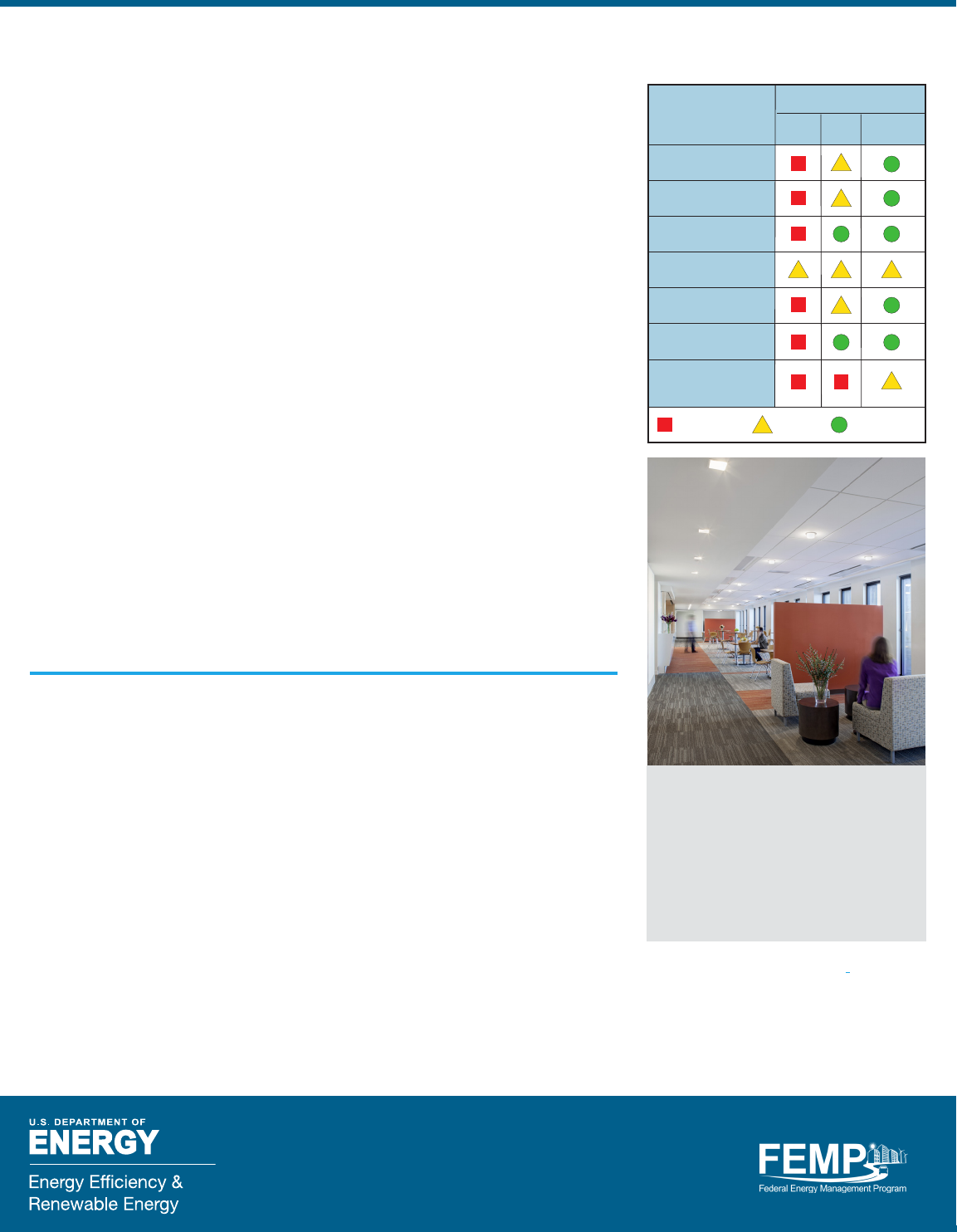
Table 5. Controls for Each LED
Troer Retrofit Option
Control
Controls integrated
into device
Available for:
TLED Kit Luminaire
None/few
Some
Many/most
Non-lighting sensors
(e.g., Bluetooth low
energy)
Communication
protocol
Works with wireless
control systems
Dims linearly
Dimming ready
Sensors integrated
into device
GSA replaced 3,300 fluorescent troers
with new LED troers at the Byron G.
Rogers Federal Building in downtown
Denver to gain lighting energy savings of
$49,200 annually. With built-in controls,
the troers can dim down to 0% output in
response to signals from daylight sensors.
Photo source: GSA.
Green Proving Ground Program enables
GSA to make sound investment decisions in
next-generation building technologies based
on their real-world performance.
Interior Lighting Campaign encourages
federal agencies to use energy-ecient
lighting and its website lists several
resources, studies, and factsheets.
U.S. Department of Defense
DoD Unified Facilities Criteria (UFC 3-530)
provides technical criteria for military
construction. UFC 3-530-01, Interior and
Exterior Lighting Systems, includes specific
information about retrofit kits and TLEDs
as well as good general guidance about
lighting.
U.S. General Services Administration
Facilities Standards for the Public Buildings
Service (P100) establishes design standards
and criteria for new buildings, major and
minor alterations, and work in historic struc-
tures for the Public Buildings Service (PBS).
FEDERAL ENERGY MANAGEMENT PROGRAM
8
DOE/EE 1544, PNNL-SA-123952
March 2017
For more information, visit:
energy.gov/eere/femp
