
Reference guide (en)
Date: 03/2020
Revision: v.1.2

MiR Fleet Reference guide (en) 03/2020 - v.1.2 ©Copyright 2017-2020: Mobile Industrial Robots A/S. 2
Copyright and disclaimer
All rights reserved. No parts of this manual may be reproduced in any form without the
express written permission of Mobile Industrial Robots A/S (MiR). MiR makes no warranties,
expressed or implied, in respect of this document or its contents. In addition, the contents of
the document are subject to change without prior notice. Every precaution has been taken in
the preparation of this manual. Nevertheless, MiR assumes no responsibility for errors or
omissions or any damages resulting from the use of the information contained.
Copyright © 2017-2020 by Mobile Industrial Robots A/S.
Contact the manufacturer:
Mobile Industrial Robots A/S
Emil Neckelmanns Vej 15F
DK-5220 Odense SØ
www.mobile-industrial-robots.com
Phone: +45 20 377 577
Email: support@mir-robots.com
CVR: 35251235

MiR Fleet Reference guide (en) 03/2020 - v.1.2 ©Copyright 2017-2020: Mobile Industrial Robots A/S. 3
Table of contents
1. About this document 5
1.1 Where to find more information 5
1.2 Version history 6
2. MiR Fleet interface 8
2.1 Signing in 8
2.2 Navigating the MiR Fleet interface 10
2.3 Getting started 11
3. Dashboards 13
3.1 Dashboards 14
3.2 Widgets 16
4. Setup 19
4.1 Scheduler 20
4.2 Robots 22
4.3 Elevators 27
4.4 Missions 30
4.5 Maps 65
4.6 Sounds 83
4.7 Transitions 84
4.8 Users 88
4.9 User groups 91
4.10 Paths 94
4.11 Path guides 96
4.12 Marker types 99

MiR Fleet Reference guide (en) 03/2020 - v.1.2 ©Copyright 2017-2020: Mobile Industrial Robots A/S. 4
4.13 Footprints 102
5. Monitoring 106
5.1 System log 106
5.2 Error logs 107
6. System 109
6.1 Settings 110
6.2 Software versions 114
6.3 Backups 114
6.4 Fleet setup 115
6.5 Evacuation zones 116
7. Help 117
7.1 MiR Fleet information 118
7.2 API documentation 118
7.3 Remote access 119
7.4 Manual 119
1. About this document
MiR Fleet Reference guide (en) 03/2020 - v.1.2 ©Copyright 2017-2020: Mobile Industrial Robots A/S. 5
1. About this document
This document describes the MiR Fleet interface. The manual is intended for administrators
of the system and users responsible for updating the system regularly, for example defining
new missions or setting up new users in the system.
1.1 Where to find more information
At www.mobile-industrial-robots.com, several additional resources are available. To access
more information, sign in to the Distributor site with your distributor account at
http://www.mobile-industrial-robots.com/en/account/. The following resources are
available:
• Distributor site > Manuals
http://www.mobile-industrial-robots.com/en/account/manuals/
This page contains the following resources:
• Quick starts describe how you start operating MiR robots quickly. This document is in
print in the box with the robots. Quick starts are available in multiple languages.
• User guides provide all the information you need to operate and maintain MiR robots.
User guides are available in multiple languages.
• Risk Analysis Guides include guidelines on how to create a risk assessment of your
robot solution.
• Commissioning guides describe how to commission your robot safely and prepare it to
operate in the workplace.
• Operating guides describe how to set up and use top modules and accessories, such as
charging stations, hooks, shelf lifts, and pallet lifts.
• Getting started guides describe how to set up products that are mainly software-
based, such as MiR Fleet and MiR AI Camera.
• Reference guides contain descriptions of all the elements of the robot interface and
MiR Fleet interface. Reference guides are available in multiple languages.
• REST API references for MiR robots, MiR hooks, and MiR Fleet.
• MiR network requirements specify the performance requirements of your network
for MiR robots and MiR Fleet to operate successfully.

1. About this document
MiR Fleet Reference guide (en) 03/2020 - v.1.2 ©Copyright 2017-2020: Mobile Industrial Robots A/S. 6
• Distributor site > Download
http://www.mobile-industrial-robots.com/en/account/download/
This page contains the following resources:
• Software and Product Release Notes for your MiR product are displayed by selecting
your product in the drop-down menu.
• CAD files of MiR products are displayed by selecting Show CAD files.
• Certificates for MiR products are displayed by selecting Show Certificates.
• Distributor site > FAQ
https://www.mobile-industrial-robots.com/en/account/faq/
This page contains frequently asked questions regarding MiR products.
• Distributor site > How to
http://www.mobile-industrial-robots.com/en/account/how-to/
This page contains how-to guides that describe how to perform specific tasks with MiR
products.
• Distributor site > Troubleshooting
https://www.mobile-industrial-robots.com/en/account/troubleshooting/
This page contains troubleshooting guides to solve common issues with MiR products.
1.2 Version history
This table shows current and previous versions of this document and their interrelations with
hardware releases.
Revision
Release
date
Description
SW
version
1.0 2019-01-17 First edition. 2.5.0
1.1 2019-03-06 Update to SW version 2.6.0.
New features in the fleet interface:
• Map zones have been reconstructed and new
zone settings are available.
• Minor corrections and improvements
throughout the manual.
2.6.0
1.2 2020-03-30 Update to SW version 2.8.0.
New features in the fleet interface:
2.8.0

1. About this document
MiR Fleet Reference guide (en) 03/2020 - v.1.2 ©Copyright 2017-2020: Mobile Industrial Robots A/S. 7
Revision
Release
date
Description
SW
version
• Marker types, used for robots driving with
shelves, has been added to the Setup section.
• A graphic Footprint editor has been added to
the Setup section making it easy to change
and create footprints.

2. MiR Fleet interface
MiR Fleet Reference guide (en) 03/2020 - v.1.2 ©Copyright 2017-2020: Mobile Industrial Robots A/S. 8
2. MiR Fleet interface
This section gives a quick overview of the MiR Fleet interface.
The interface is responsive and automatically adapts to your use of smartphone, tablet, or
PC.
2.1 Signing in
The interface comes with three default access levels:
• Distributor - the MiR distributor
• Administrator - the end-customer’s production engineer with technical responsibility for
the robot
• User - the daily operator(s) of the robot
There are two ways in which you can sign in to the MiR Fleet interface:
• Username and password
• PIN code

2. MiR Fleet interface
MiR Fleet Reference guide (en) 03/2020 - v.1.2 ©Copyright 2017-2020: Mobile Industrial Robots A/S. 9
System permissions are handled per user group whereas login credentials are handled per
individual user. Read more in the sections Users on page88 and User groups on page91.
Accessing the interface
The user interface is accessed by connecting to the MiR Fleet WiFi and opening your
preferred web browser. Enter the IPaddress of the MiR Fleet or enter mir.com in the
browser's address bar.
The fleet interface can be accessed via Chrome, Safari, Firefox, and Edge.
Username and password
Enter your username and password to sign in to the MiR Fleet interface.
Default login credentials
The default usernames and passwords are:
Distributor
• Username: Distributor
• Password: contact MiR Support
Administrator

2. MiR Fleet interface
MiR Fleet Reference guide (en) 03/2020 - v.1.2 ©Copyright 2017-2020: Mobile Industrial Robots A/S. 10
• Username: Admin
• Password: admin
User
• Username: User
• Password: user
PIN code
Select the PIN code tab and enter a four-digit PIN code. There is no preconfigured PIN code.
2.2 Navigating the MiR Fleet interface
To access a section in the MiR Fleet interface, first select an item on the main menu, then
the relevant sub-menu. The section appears in the main window.

2. MiR Fleet interface
MiR Fleet Reference guide (en) 03/2020 - v.1.2 ©Copyright 2017-2020: Mobile Industrial Robots A/S. 11
For example, to go to the Sounds section,select Setup on the main menu, then select
Sounds on the submenu bar.
2.3 Getting started
The interface supports multi-level user access, and tailored dashboards. To get started, you
first need to set up how different users may operate the robot. You can set the access level
for each user and create individual dashboards that include the main functions they need to
operate MiR Fleet. Before the robot can operate, you must also set up the system by
creating maps and missions for the robot to use.
User setup
You must set up the various levels of users that will be operating MiR Fleet, and tailor each
group to the extent of access they require. You do this in the following steps:
1. Set up users, see Users on page88.
2. Define user groups, see User groups on page91.
3. Create dashboards tailored to different users’ tasks, see Dashboards on page14.

2. MiR Fleet interface
MiR Fleet Reference guide (en) 03/2020 - v.1.2 ©Copyright 2017-2020: Mobile Industrial Robots A/S. 12
System setup
For a smooth running fleet, you must define one or more maps where the robots can
operate, including features, such as positions, and preferred or forbidden drive zones that
contribute to an organized workflow. To define the tasks the robots should execute within a
map, you must create new missions for each task. You do this in the following steps:"
• Create a map, see Maps on page65.
• Edit the map: add positions, drive zones etc., see Mapping tools on page68.
• Create missions, see Missions on page30.

3. Dashboards
MiR Fleet Reference guide (en) 03/2020 - v.1.2 ©Copyright 2017-2020: Mobile Industrial Robots A/S. 13
3. Dashboards
This section describes the items in the Dashboards menu.
The Dashboards menu displays all dashboards currently available on the robot.
In the subsection Dashboards , you can create new dashboards and edit existing ones. Select
Dashboards to open the list of dashboards, and select the Create dashboard button to open
the dashboard designer.
The Dashboards menu contains the following
items:
3.1 Dashboards 14
3.2 Widgets 16

3. Dashboards
MiR Fleet Reference guide (en) 03/2020 - v.1.2 ©Copyright 2017-2020: Mobile Industrial Robots A/S. 14
3.1 Dashboards
Dashboards are an easy way for different user groups to control the fleet giving direct
access to their individual key functions. A dashboard is made up of a number of widgets each
representing a feature in the system, such as a particular mission, the map the robots are
running in, or the current mission queue.
The system comes with a default dashboard and, in addition, you may create an unlimited
number of customized dashboards.
Create dashboard
Enter a name in the Name field to create a new dashboard. Select Create dashboard to
continue to the design section. Design the dashboard by adding widgets that represent the
features you want to assign to the dashboard.

3. Dashboards
MiR Fleet Reference guide (en) 03/2020 - v.1.2 ©Copyright 2017-2020: Mobile Industrial Robots A/S. 15
Dashboard designer
Design the dashboard by selecting widgets from the menus in the top bar. Resize the widgets
by pulling the arrow in the lower right-hand corner and rearrange their order by click-
dragging. Some widgets require further settings. For example, you must select a particular
mission for mission buttons. To do this, select the pen icon in the lower left corner and select
the wanted action.
Edit dashboard
The dashboard design can be edited and widgets added or removed.

3. Dashboards
MiR Fleet Reference guide (en) 03/2020 - v.1.2 ©Copyright 2017-2020: Mobile Industrial Robots A/S. 16
Delete dashboard
You can delete all dashboards that are created by you or another member of the user group
you belong to.
3.2 Widgets
This section describes the dashboard widgets.
Maps
Locked fleet map
A Locked fleet map widget makes the selected map visible on the dashboard. Select the
map that should be used for the locked fleet map.

3. Dashboards
MiR Fleet Reference guide (en) 03/2020 - v.1.2 ©Copyright 2017-2020: Mobile Industrial Robots A/S. 17
Locked robot map
A Locked robot map widget makes the active map of the selected robot visible on the
dashboard. The robot is always shown in the middle of a locked map. Select the robot you
want shown on the dashboard.
Missions
Mission button
You can start a mission from the dashboard by adding a Mission button widget and
selecting a predefined mission.
Mission queue
You can have the mission queue displayed on the dashboard by selecting a Mission queue
widget.
Mission group
You can select a mission group and have all missions from that group displayed on the
dashboard by adding a Mission group widget.

3. Dashboards
MiR Fleet Reference guide (en) 03/2020 - v.1.2 ©Copyright 2017-2020: Mobile Industrial Robots A/S. 18
Miscellaneous
Distributor
This widget shows information about the distributor if any distributor data has been entered
in the Distributor data section under System > Settings.
Log-out button
The Log-out button allows you to log off via the dashboard. This is useful on small devices
where there is no other log-out button.

4. Setup
MiR Fleet Reference guide (en) 03/2020 - v.1.2 ©Copyright 2017-2020: Mobile Industrial Robots A/S. 19
4. Setup
This section describes the items in the Setup menu.
The Setup menu contains the following items:
4.1 Scheduler 20
4.2 Robots 22
4.3 Elevators 27
4.4 Missions 30
4.5 Maps 65
4.6 Sounds 83
4.7 Transitions 84
4.8 Users 88
4.9 User groups 91
4.10 Paths 94
4.11 Path guides 96
4.12 Marker types 99
4.13 Footprints 102

4. Setup
MiR Fleet Reference guide (en) 03/2020 - v.1.2 ©Copyright 2017-2020: Mobile Industrial Robots A/S. 20
4.1 Scheduler
Missions to be carried out by MiR Fleet robots are handled in Scheduler. You can schedule
which robot group should execute a mission, at what date and time, and set the priority of
the mission. Missions and robot groups must be created before proper scheduling can be
done. Go to Robot > Missions to create new missions, and go to Fleet > Robots to create
robot groups.
See also Robots on page22.
Schedule a mission
Schedule a mission by selecting the earliest start, a robot, and what priority the mission
should have. Selecting Run as soon as possible schedules the mission to the queue of
missions. Selecting High priority schedules the mission to run as the first mission before all
other scheduled missions.

4. Setup
MiR Fleet Reference guide (en) 03/2020 - v.1.2 ©Copyright 2017-2020: Mobile Industrial Robots A/S. 21
Edit schedule for mission
Edit a mission if you want to change the parameters you selected when creating the mission.

4. Setup
MiR Fleet Reference guide (en) 03/2020 - v.1.2 ©Copyright 2017-2020: Mobile Industrial Robots A/S. 22
4.2 Robots
You can add new robots to MiR Fleet by scanning the network for robots or adding them
manually.
Use the Scan for robots button to find available robots on the network and the Add robot
manual button if you want to add robots by entering their IP addresses.
In the overview of robots on the fleet, each robot has an icon in the top left corner indicating
its status.
• A blue checkmark indicates that the robot is active.
• A red cross indicates that the robot is not yet active or has been deactivated.
• A yellow exclamation mark indicates that the robot has a wrong software version. All
robots and MiR Fleet must have the same software version.
Select Show info to see all details on the robot's status, IP address etc. You can also open
the robot's own interface by selecting Show info and then the Go to robot interface button.

4. Setup
MiR Fleet Reference guide (en) 03/2020 - v.1.2 ©Copyright 2017-2020: Mobile Industrial Robots A/S. 23
Add robot manually
Add a robot manually by entering the robot's IP address, and select or create a robot group
or charging group it should belong to. Deselect Active in MiR Fleet if the robot should not be
part of the active fleet. Select Factory reset the robot before adding it if you want to reset
the robot to default values before adding it to the fleet.
Note: Factory resetting the robot completely resets the robot's system to default factory
values.
Scan for robots
Scanning for robots is a fast way to add robots on the same network to the fleet. It searches
for the nearest robot WiFi addresses and lists the found robots on the screen. Subsequently
you can add the robots to the fleet.

4. Setup
MiR Fleet Reference guide (en) 03/2020 - v.1.2 ©Copyright 2017-2020: Mobile Industrial Robots A/S. 24
Groups
Robots controlled by MiR Fleet can be organized in groups each of which are dedicated to
specific missions. Each robot can be assigned to one robot group and one charging group.
A robot group is a collection of mission groups that all robots in the group are allowed to
execute. For example, you can use robot and mission groups to restrict a group of MiR Hook
robots to only perform missions for transporting carts.
A charging group is used to organize charging stations into group based on, for example,
their location. This is useful if you have enabled auto charging, and you have a set of
chargers and robots in two isolated areas. Using charging groups ensures that robots from
one area do not try to dock to charging stations in the second area.
You can read more about mission groups in the section Creating a mission on page32.
Create robot or charging group
Create a group by selecting a name, and choose if it should be a robot group or a charging
group. If you create a robot group, deselect Allow all mission groups to select the specific
mission groups the robot group is allowed to run.

4. Setup
MiR Fleet Reference guide (en) 03/2020 - v.1.2 ©Copyright 2017-2020: Mobile Industrial Robots A/S. 25
Edit group
Edit the name of the robot or charging group.
For robot groups, you can deselect Allow all mission groups to select from all available
missions groups.
Show info
You can open a detailed view of the individual robots connected to MiR Fleet.

4. Setup
MiR Fleet Reference guide (en) 03/2020 - v.1.2 ©Copyright 2017-2020: Mobile Industrial Robots A/S. 26
Select Show info to see and edit the details of the robot, such as its name and robot group.
You can also view statistics of the particular robot's performance in percentage, such as
errors, idle time, charging time, and missions, and view the robot's map.
Select Go to robot interface to open the robot's interface in a new tab.
4. Setup
MiR Fleet Reference guide (en) 03/2020 - v.1.2 ©Copyright 2017-2020: Mobile Industrial Robots A/S. 27
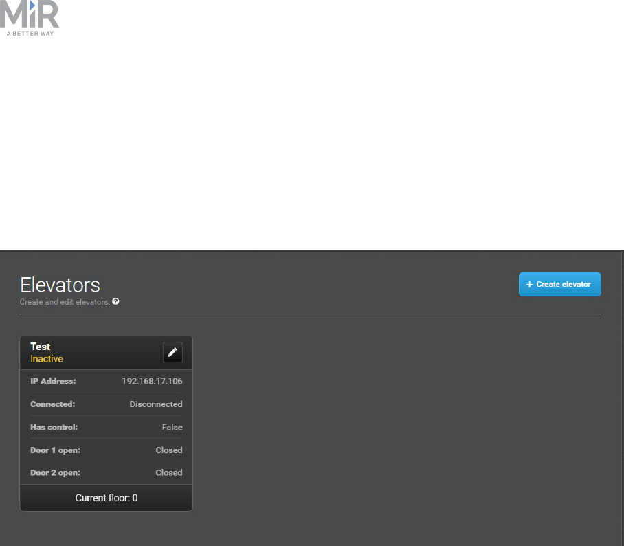
4.3 Elevators
In installations with an elevator, transitions from one map (floor) to another are handled
automatically by MiR Fleet. When an order is given to move to a position in a map
representing a different floor, the fleet control takes over and brings the robot into the
elevator and out again on the correct floor. MiR Fleetthen handles the map switch internally.

4. Setup
MiR Fleet Reference guide (en) 03/2020 - v.1.2 ©Copyright 2017-2020: Mobile Industrial Robots A/S. 28
Create elevator
The steps for setting up an elevator are:
1. Set up name and IP address or the elevator, and set the elevator active or inactive in
Create elevator.
2. Add floors with information about maps, positions, entry, and exit missions in Edit
elevator.
The Create elevator dialog has the following fields:
• Name
Enter a name for the elevator
• IP address
Enter a valid IP address for the elevator. The IP address is provided by the elevator system
integrator.
• Turn in place
Select whether or not the robot is allowed to turn in the elevator. Turning in the elevator
might be relevant if the robot enters and exits the same elevator door and it must face
front in both instances.
• Active
Select whether or not the elevator should be actively used in the fleet.

4. Setup
MiR Fleet Reference guide (en) 03/2020 - v.1.2 ©Copyright 2017-2020: Mobile Industrial Robots A/S. 29
Edit elevator
In Edit elevator you can add floors to elevators, and change the settings of an elevator.
Select +Add floor to add a new floor.
When you add a new floor, you must enter the following details:
• Floor
Enter the specific floor number. Floor designations must be numbers, for example,
Ground floor could be represented by 0, and Basement by -1.
• Map
Select the map that represents the floor. The map must include two robot positions that
will enable the switching from one map to another.
• Position in the elevator
Select the robot position representing the robot inside the elevator.
• Position in front of the elevator
Select the robot position representing the robot outside the elevator. This is the position
the robot goes to while waiting for the elevator to arrive and the doors to open.

4. Setup
MiR Fleet Reference guide (en) 03/2020 - v.1.2 ©Copyright 2017-2020: Mobile Industrial Robots A/S. 30
• Entry mission
An entry mission is not mandatory. An example of an entry mission could be a sound the
robot plays as it enters the elevator. An entry mission must include a Move action with a
variable position.
• Exit mission
An exit mission is not mandatory. An example of an entry mission could be a sound the
robot plays as it exits the elevator.
• Door
Select 1 or 2 depending on the number of exits and entries in the elevator, and if the
robot should use the same door to enter and exit the elevator or exit through the one
opposite the entry.
1: The robot makes a 180° turn inside the elevator and exits through the same door it
entered.
2: The robot does not turn and exits through the door opposite the entry door.
Select Update elevator to save the settings.
Delete elevator
Delete an elevator by selecting Delete in the Edit elevator section.
4.4 Missions
A mission is a predefined series of actions that a robot within the fleet can be set to perform.
A mission can be a simple transportation task between defined positions or a more complex
task that includes both moving between positions and performing actions, such as opening
an automatic door via Bluetooth signal, sounding a horn, or sending an email on arrival at a
position.

4. Setup
MiR Fleet Reference guide (en) 03/2020 - v.1.2 ©Copyright 2017-2020: Mobile Industrial Robots A/S. 31
Missions are started by adding them to the schedule. It is possible to add them to the
immediate mission queue by selecting Run as soon as possible when scheduling it.
Start mission
You can enqueue a mission in one of the following ways:
From a dashboard
You can configure a Mission button widget on a dashboard.
From the Scheduler menu
To enqueue a mission:
• Select Missions to schedule and run a mission.

4. Setup
MiR Fleet Reference guide (en) 03/2020 - v.1.2 ©Copyright 2017-2020: Mobile Industrial Robots A/S. 32
If there are variable parameters in a mission, for example a variable position, you will be
asked to select the position when adding the mission to the queue.
The selected parameters are shown in blue text.
Creating a mission
This section describes what a mission is and how to make one.
MiR robots function through missions that the user creates. A mission is made up of actions,
such as: move actions, logic actions, cart pick-up/delivery and sounds, which can be put
together as building blocks to form a mission with as many actions as needed. Missions
themselves can also be embedded into other missions.
Most actions have adjustable parameters, for example which position to go to. Most actions
also have adjustable variables where the user is asked a question regarding the variable
every time the mission is added to the queue. This can be practical in cases where the robot
performs the same series of actions in different areas of the facility that requires different
variables in the mission action.
When you create a mission, you can save it in the default Missions group, or can choose to
save it in any of the available actions groups. The actions groups are found in the top bar of
the mission editor window, and you can distinguish missions from actions by the small icons
shown next to their names: missions have a target icon , and actions have a running-man
icon .

4. Setup
MiR Fleet Reference guide (en) 03/2020 - v.1.2 ©Copyright 2017-2020: Mobile Industrial Robots A/S. 33
You can find more information about mission groups in the following section, Mission
groups and about actions in Mission actions on page38.
The Mission section also comes with a set of default missions that you can use and/or
modify.
Fill in the following information to create a misison:
• Name
The name must be unique and is used to identify the mission. For example, Go to charging

4. Setup
MiR Fleet Reference guide (en) 03/2020 - v.1.2 ©Copyright 2017-2020: Mobile Industrial Robots A/S. 34
station, Deliver spare parts or Warehouse to production line 1.
• Mission group
Select which group you want the mission to be part of.
• Site
If you are using more than one site, select which site you want the mission to belong to.
Select Create mission to save the settings.
Mission groups
Each mission group has a number of predefined actions that can be selected when you build
the mission. One mission can contain actions from several groups. When you save the new
mission, it will be placed in the selected group and can be used as a separate mission or as
an embedded mission in other missions.

4. Setup
MiR Fleet Reference guide (en) 03/2020 - v.1.2 ©Copyright 2017-2020: Mobile Industrial Robots A/S. 35
Create mission group
If you don't want to use any of the default group names, you can create your own group(s)
and save missions here. New groups will be shown in the top bar next to the default groups
and contain any mission(s) you want to add to it

4. Setup
MiR Fleet Reference guide (en) 03/2020 - v.1.2 ©Copyright 2017-2020: Mobile Industrial Robots A/S. 36
Mission editor
A mission is built from actions that you pick from the menus in the top bar. You can also pick
already created missions and embed them in new missions.
Actions and missions are grouped together in the top bar menus. All predefined actions are
identified by a running-man icon. User created missions are placed together with actions in
the group to which you append them and can be distinguished from actions by a target icon
next to their names.
When you have picked the actions you want in your mission, do the following:
1. Drag the actions up or down with the four-headed arrow at the far left of the action line
to sort them in the desired order. The actions are executed in a top-to-bottom order.
2. Set the parameters for the selected action by selecting the gear icon at the far right of
the action line.

4. Setup
MiR Fleet Reference guide (en) 03/2020 - v.1.2 ©Copyright 2017-2020: Mobile Industrial Robots A/S. 37
Change mission settings
To change the name and mission group of a mission, in the mission editor window, select the
gearwheel next to the name of the mission.
In the Mission editor window, move the mouse over the name of the mission, and select the
gearwheel.
Save mission
When you have completed the mission by adding all actions and sorted them in the desired
order, select Save to save the mission.
Save mission as
You can save a copy of a mission and give it a new name. That way it is easy to create a new
mission based on an existing one.

4. Setup
MiR Fleet Reference guide (en) 03/2020 - v.1.2 ©Copyright 2017-2020: Mobile Industrial Robots A/S. 38
In the Mission editor window, select Save as.
Mission actions
Actions used in missions are in the Groups tool bar at the top of the window.

4. Setup
MiR Fleet Reference guide (en) 03/2020 - v.1.2 ©Copyright 2017-2020: Mobile Industrial Robots A/S. 39
Variables
All actions that require the user to specify something, for example, a position, a number of
retries, a distance, or a subject text, have the option to define a variable. We recommend
naming variables in the form of a question that describes what the value you are inserting
should be used for. The question pops up on the operator’s user interface every time the
mission is queued and the user must select an answer before the mission can begin.

4. Setup
MiR Fleet Reference guide (en) 03/2020 - v.1.2 ©Copyright 2017-2020: Mobile Industrial Robots A/S. 40
Create variables
In the Name field, enter a question that describes what the variable is used for, for example,
“How far should the robot move?” In the Default value field, enter a default distance.
Move
This mission group contains the following actions.
Action description Parameter descriptions
Adjust localization
An Adjust localization action adjusts the
robot to the correct position in the map.
This is useful if it has to move through an
area with many dynamic obstacles where
the localization is likely to drift.
No adjustable parameters.
Check position status
Positions of the following types can have
the states free or occupied:
• Robot position
• Cart position
• Shelf position
• Pallet rack position
• Staging position
Position
Select a position from the drop-down list,
or select the XYZ icon to define a
variable.
Option
Select if the robot should check if a
position is empty or occupied, or select
the XYZ icon to define a variable

4. Setup
MiR Fleet Reference guide (en) 03/2020 - v.1.2 ©Copyright 2017-2020: Mobile Industrial Robots A/S. 41
Action description Parameter descriptions
This action checks the state of the position
for a given amount of time. If the
condition in the action is satisfied, the
robot continues executing the mission.
Otherwise, the robot raises an error.
Example: Use this action for the following
purposes:
• Check whether the load is on the pallet
rack before docking to the rack.
• Check whether the cart is in position
before picking it up with the hook.
• Check whether the target position is
free.
Timeout (seconds)
Enter the maximum time during which
the robot checks the position status. If the
position status does not match the option
selected for this position (free, occupied,
etc.) and the time expires, the robot
shows an error.
Docking
A Docking action sets a position the robot
should dock to, for example, a charging
station or a V, VL, or L-marker.
Marker
Select a marker from the drop-down list
or select the XYZ icon to define a
variable.
Move
A Move action defines a map position the
robot should move to.
Position
Select a position from the drop-down list,
or select the XYZ icon to define a
variable.
Retries (Blocked Path)
Set the number of times the robot should
try to reach the position if the path is
blocked, or select the XYZ icon to define a
variable. If, after the number of retries,
the path is still blocked, the robot stops
and produces an error message.
Distance threshold

4. Setup
MiR Fleet Reference guide (en) 03/2020 - v.1.2 ©Copyright 2017-2020: Mobile Industrial Robots A/S. 42
Action description Parameter descriptions
Depending on how accurately the robot is
required to position itself on the goal
position, the threshold can be increased
or decreased. The default is 0.1 m.
Move to coordinate
A Move to coordinate action defines an
X, Y position on the map the robot should
move to. The map's origin, i.e. the 0,0
position with 0 orientation, is located at
the point where the robot began mapping.
If in doubt of the map's origin, you may
create a fixed position with those values
as a reference point for the Move to
coordinate position you wish to create.
X
Enter the X (horizontal) map position the
robot should move to, or select the XYZ
icon to define a variable.
Y
Enter the Y (vertical) map position the
robot should move to, or select the XYZ
icon to define a variable.
Orientation
Enter the orientation in degrees, that is
the way the robot should turn relatively
to the 0-orientation when arriving on the
position, or select the XYZ icon to define
a variable. A positive value rotates the
robot counterclockwise, and a negative
value rotates it clockwise.
Retries (Blocked Path)
Set the number of times the robot should
try to reach the position if the path is
blocked, or select the XYZ icon to define a
variable. If, after the number of retries,
the path is still blocked, the robot stops
and produces an error message.
Distance threshold
Depending on how accurately the robot is
required to position itself on the goal

4. Setup
MiR Fleet Reference guide (en) 03/2020 - v.1.2 ©Copyright 2017-2020: Mobile Industrial Robots A/S. 43
Action description Parameter descriptions
position, the threshold can be increased
or decreased. The default is 0.1 m.
Planner settings
A Planner settings action allows you to
set the desired speed of the robot, to
change the settings for how much the
robot is allowed to deviate from its
planned path, and how it should filter out
obstacles when driving.
Path deviation and obstacle clearing can
be used, for example, if you want your
robot to follow its path without it
attempting to maneuver around any
dynamic obstacles, the so-called Line-
following mode.
Planner settings
Default speed: sets the default speed of
the robot while it runs this mission.
Path deviation: sets the maximum
distance the robot is allowed to deviate
from its path before it generates a new
path. Setting the value to 0 means no
deviation is allowed.
Path timeout sets the amount of time
the robot will wait for the path to clear
before generating a new one. If you set
the value to -1 the robot will wait
indefinitely for obstacles to move out of
its way instead of generating a new path.
Obstacle history clearing sets how the
robot will clear its obstacle history during
driving. The available options are, No
clearing, Clear all, Clear in front of
robot.
Relative move
A Relative move action defines an X and
a Y distance you want the robot to move
and an orientation you want it to turn
relative to its current position. A Relative
move can be used for example, to move
the robot away from docking positions in
narrow passages.
X
Enter a value in meters for how much the
robot should move forwards or
backwards from its current position. A
positive value moves the robot forwards
and a negative value moves it backwards.
Select the XYZ icon if you want to define
a variable.
Y

4. Setup
MiR Fleet Reference guide (en) 03/2020 - v.1.2 ©Copyright 2017-2020: Mobile Industrial Robots A/S. 44
Action description Parameter descriptions
When using a Relative
move, be aware that the
robot can move into
Forbidden zones and
through walls on the map.
The robot will still drive
with Collision detection and
will not hit anything, but if
there is a black line on the
map, and the wall does not
exist physically, it will drive
through it.
Enter a value in meters for how much the
robot should move left or right from its
current position. A positive value moves
the robot to the right and a negative
value moves it to the left. Select the XYZ
icon if you want to define a variable.
Orientation
Enter a value in degrees for how much
the robot should turn (yaw) when
finalizing the Relative move. A positve
value moves it counterclockwise and a
negative value moves it clockwise. Select
the XYZ icon if you want to define a
variable.
Maximum linear speed
Enter a value in meters per second for
the max. forward or backward speed
during the Relative move, or select the
XYZ icon to define a variable.
Maximum angular speed
Enter a value in meters per second for
the max. turn speed during the Relative
move, or select the XYZ icon to define a
variable.
Collision detection
Select the check box to turn on automatic
Collision detection. Collision detection
may be turned off if the robot needs to
turn around its own center in tight
spaces, for example, in an elevator. If
collision detection is on, the robot will try
to turn, but will go into emergency stop

4. Setup
MiR Fleet Reference guide (en) 03/2020 - v.1.2 ©Copyright 2017-2020: Mobile Industrial Robots A/S. 45
Action description Parameter descriptions
as soon as it detects the surrounding
walls.
Set footprint
A Set footprint action makes it possible
to change the robot's default footprint.
This can be necessary, for example, if the
robot carries a top module with larger
proportions than the robot's own or you
want to extend the footprint when the
robot tows a cart. The footprint is shown
as a shadow around the robot on the map.
Footprint
Select a created footprint, or select the
XYZ icon to define a variable. Footprints
must be created in the footprint editor
found under Setup >Footprints.
Switch map
A Switch map action is required if the
robot needs to switch automatically from
one map to another within a mission, for
example, if the robot is operating in a
large site that includes more than one
map. The maps must have overlapping
areas where the robot can locate itself in
the physical environment. Switch map
actions are the basis for Transitions
(Setup > Transitions) which handle map
switches automatically once they are set
up. The robot automatically chooses the
start position when sent to a position in
another map.
Entry Position
In the map you are switching to, select
the position the robot should start from
after the map transition, or select the
XYZ icon to define a variable.
The Switch map action must be preceded
by a Move action to the position in the
current map that physically overlaps the
goal position you select here. The overlap
of the entry and goal positions in the
physical area is important for the robot to
localize itself in the new map.

4. Setup
MiR Fleet Reference guide (en) 03/2020 - v.1.2 ©Copyright 2017-2020: Mobile Industrial Robots A/S. 46
Battery
This mission group contains the following actions.
Action descriptions Parameter descriptions
Charging
A Charging action is used to make the
robot go to a charging station for
automatic battery recharge. The action is
defined by setting a minimum charging
time and a minimum charging
percentage. When the first of those are
reached, the action is completed. For
example, if you set the minimum time to
30 minutes and the minimum percentage
to 80%, the robot will charge for
minimum 30 minutes or until it reaches a
battery level of 80%. You may also choose
to ignore either time or percentage.
A Charging action must be preceded by a
Docking action where the robot moves to
a previously defined charging position
near the charging station.
Minimum Time
Set a minimum amount of time the robot
should charge before it moves on, or
select the XYZ icon to define a variable.
The system will compare the set
minimum time with the minimum
percentage, and when the first of those
two requirements is fulfilled, the mission
continues.
You may skip defining a minimum time by
selecting the Ignore value check box. The
robot will then charge until the minimum
battery percentage level is reached.
Minimum Percentage
Enter the minimum battery percentage
the robot should charge to before it
moves on, or select the XYZ icon to define
a variable. The system will compare the
set minimum percentage with the
minimum time, and when the first of
those two requirements is fulfilled, the
mission continues. You may skip defining
a minimum percentage by selecting the
Ignore value check box. The robot will
then charge until the minimum charge
time is reached.
Charge until new mission in queue
Select this check box if you want the robot
to continue charging until it receives a

4. Setup
MiR Fleet Reference guide (en) 03/2020 - v.1.2 ©Copyright 2017-2020: Mobile Industrial Robots A/S. 47
Action descriptions Parameter descriptions
new mission. If selected, the robot stays
in the charging station until it receives a
new mission, but not until at least one of
the criteria for minimum time or
minimum percentage is reached.
If deselected, the robot leaves the
charging station when either of the two
charging criteria are reached regardless
of queued missions.
Logic
This mission group contains the following actions.
Action descriptions Parameter descriptions
Break
A Break action is used to interrupt a loop
action.
No adjustable parameters.
Continue
A Continue action is used to abort the rest
of a loop action and continue from the
start.
No adjustable parameters.
If
If actions make it possible to check battery
level, number of pending missions, PLC
registers, or input from I/O modules and
then define which actions or missions
should be performed if the conditions
return either true or false. You may use
one or more actions or missions to define
Compare
Select either Battery Percentage, PLC
Register, Pending Missions, or I/O
input, or select the XYZ icon to define a
variable.
Module
For I/O inputs: select an I/O module from

4. Setup
MiR Fleet Reference guide (en) 03/2020 - v.1.2 ©Copyright 2017-2020: Mobile Industrial Robots A/S. 48
Action descriptions Parameter descriptions
both true and false conditions.
Battery Percentage: An If action on
battery percentage checks if the battery
percentage is below, above, or equal to a
set limit and, depending on the result,
either sends the robot to a charging
station or continues the mission. The True
action could be a previously defined
charging mission. The False action could
be any alternative actions or missions, but
may also be left blank. In that case, the
robot will continue to the next step in the
mission.
Pending missions: An If action on pending
missions checks if the number of pending
(queued) missions is below, above or
equal to a set number. You then set
actions that define what the robot should
do if the set condition returns true or
false. An example could be to send the
robot to a charging station if the number
of queued missions exceeds a certain
amount.
PLC Register: An If action on a PLC
register checks if the register is set to a
certain value, for example, register 6=1
indicating that a lift is lowered when the
robot arrives at a shelf. The True action
(the lift is lowered) could then be a Wait
for PLC Register action, for example, wait
for register 6 to reset to 0.
I/O input: An If action on an I/O input
checks if the register is set to a certain
value, for example, register 6=1 indicating
the drop-down list, or select the XYZ icon
to define a variable.
Index
For PLC registers: enter the required
index number (Integer registers 1-100,
Floating point registers 101-200), or
select the XYZ icon to define a variable.
Operator
Select the arithmetic operator you want
to use, or select the XYZ icon to define a
variable.
Operators are arithmetic operators used
to specify the compare mission, for
example, use the < operator to specify “If
Battery percentage is below 50 percent”.
The available operators are:
• == ‘equal to’
• != ‘not equal to’
• > ‘greater than’
• >= ‘greater than or equal to’
• < ‘lesser than’
• <= ‘lesser than or equal to’.
Value
Enter the value for the selected register,
or select the XYZ icon to define a
variable.

4. Setup
MiR Fleet Reference guide (en) 03/2020 - v.1.2 ©Copyright 2017-2020: Mobile Industrial Robots A/S. 49
Action descriptions Parameter descriptions
that a lift is lowered when the robot
arrives at a shelf. The True action (the lift
is lowered) could then be a Wait for PLC
register action, for example, wait for
register 6 to reset to 0.
Loop
A Loop action makes it possible to have
the robot repeat a mission either a
specified number of times or endlessly
(until stopped by an operator). Drag
actions or predefined missions into the
loop action to define the sequence of
actions the robot will repeat. A loop can
be interrupted with a Break action.
Iterations
Set the number of times the robot should
run the loop, or select the XYZ icon to
define a variable.
Content
Insert the actions that should be
performed in each loop iteration.
Pause
A Pause action pauses the mission
execution until an operator selects
Continue.
This can be used in missions where the
robot should wait for an operator to do
something, for example, placing items on
the robot and manually sending the robot
on to another position by selecting
Continue.
No adjustable parameters.
Prompt user
A Prompt user action can be used when it
is required to stop and ask the operator
what the next step in the mission should
be. The action consists of a Yes action, a
No action and a Time-out action. The
Question
Write a question which can be answered
with a yes or a no, or select the XYZ icon
to define a variable. The operator will be
asked to answer yes or no to the
question, and if the answer is no, the
robot will carry on with the No action.

4. Setup
MiR Fleet Reference guide (en) 03/2020 - v.1.2 ©Copyright 2017-2020: Mobile Industrial Robots A/S. 50
Action descriptions Parameter descriptions
operator will be asked, for example, “Do
you want to go to position X?”. If the
operator answers Yes, the robot will go to
position X. If the operator answers No, the
robot will carry on to the defined No
action, for example, move to an
alternative position. If the operator does
not answer yes or no within a given time,
the Time-out action will be executed, for
example, sending an email.
User group
Select which User group the mission is
intended for or select the XYZ icon to
define a variable.
Timeout (seconds)
Set a timeout for when the robot should
continue if the user does not answer the
question. If the timeout is reached, the
robot will execute the actions in the
Timeout scope.
Return
A Return action is used to abort a mission.
It can be used, for example, as catch
action in a Try/Catch action.
No adjustable parameters.
Wait
A Wait action pauses the mission in a
given period of time.
Time
Set an amount of time the robot should
wait before moving to next action in the
mission.
While
While actions make it possible to check
battery level, number of pending missions,
PLC registers, or input from I/O modules
and then define which actions or missions
should be performed if the conditions
return either true or false. You may use
one or more actions or missions to define
the while conditions.
Battery Percentage: A While action on
battery percentage checks if the battery
Compare
Select either Battery Percentage, PLC
Register, Pending Missions, or I/O
input, or select the XYZ icon to define a
variable.
Module
For I/O inputs: select an I/O module from
the drop-down list, or select the XYZ icon
to define a variable.
Index

4. Setup
MiR Fleet Reference guide (en) 03/2020 - v.1.2 ©Copyright 2017-2020: Mobile Industrial Robots A/S. 51
Action descriptions Parameter descriptions
percentage is below or above a set limit
and, depending on the result, either sends
the robot to a charging station or
continues the mission.
PLC Register: A While action on a PLC
register checks if the register is set to a
certain value, for example, register 6=1
indicating that a lift is lowered when the
robot arrives at a shelf.
Pending missions: A While action on
pending missions checks if the number of
pending (queued) missions is below, above
or equal to the set number. You then set
an action that defines what the robot
should do if the set condition returns True.
An example could be to send the robot to
a charging station if the number queued
missions exceeds a certain amount.
I/O input: A While action on an I/O input
checks if the register is set to a certain
value, for example, register 6=1 indicating
that a lift is lowered when the robot
arrives at a shelf. The True action (the lift
is lowered) could then be a Wait for PLC
register action, for example wait for
register 6 to reset to 0.
For PLC registers: enter the required
index number (Integer registers 1-100,
Floating point registers 101-200), or
select the XYZ icon to define a variable.
Operator
Select the arithmetic operator you want
to use, or select the XYZ icon to define a
variable.
Operators are arithmetic operators used
to specify the compare mission, for
example, use the < operator to specify “If
Battery percentage is below 50 percent”.
The available operators are:
• == ‘equal to’
• != ‘not equal to’
• > ‘greater than’
• >= ‘greater than or equal to’
• < ‘lesser than’
• <= ‘lesser than or equal to’.
Value
Enter the value for the selected register,
or select the XYZ icon to define a
variable.
Content
Insert the actions that should be
performed in each loop iteration.

4. Setup
MiR Fleet Reference guide (en) 03/2020 - v.1.2 ©Copyright 2017-2020: Mobile Industrial Robots A/S. 52
Error handling
This mission group contains the following actions.
Action descriptions Parameter descriptions
Create log
A Create log action is used to create user
generated error logs. A Create log action
can be generated as an error log
(Monitoring > Error logs) under the
module name User, showing the
description entered here. This is useful in,
for example, a try/catch action where a
log is created when catching an
unsuccessful try.
Description
Enter a description for the log type you
want to create, or select the XYZ icon to
define a variable. An example of a
description could be “Mission x fail log”
Throw error
A Throw error action is used to enter an
error message that will be shown in the
user interface when the mission is run.
Message
Enter the message you want displayed on
the user interface when the mission is
run, or select the XYZ icon to define a
variable.
Try/Catch
A Try/Catch action is a way to reinforce
missions by defining an alternative action
if the first choice action fails. This will in
many cases prevent a mission from
discontinuing in case, for example, a
position is blocked. A Try/Catch action
consists of one action Try which the robot
should attempt to complete, and a second
action Catch which is used in case the Try
action fails.
Try
Select the action(s) that should be
attempted.
Catch
Select the action that should be
performed if the action(s) within Try
fails.

4. Setup
MiR Fleet Reference guide (en) 03/2020 - v.1.2 ©Copyright 2017-2020: Mobile Industrial Robots A/S. 53
Sound/Light
This mission group contains the following actions.
Action descriptions Parameter descriptions
Show light
A Show light action sets a light that the
robot will show at a given point in the
mission. The action is a combination of
light effect, speed, color, and intensity.
Effect
Select a light effect from the drop-down
list, for example, 'Blink', or select the XYZ
icon to define a variable.
Speed zones
Select a fast or slow speed from the drop-
down list, or select the XYZ icon to define
a variable.
Color 1
Select a color from the drop-down list, or
select the XYZ icon to define a variable. If
you select two different colors for Color 1
and 2, the robot will alternate between
the two.
Color 2
Select a color from the drop-down list, or
select the XYZ icon to define a variable. If
you select two different colors for Color 1
and 2, the robot will alternate between
the two.
Intensity
Set the intensity of the light, or select the
XYZ icon to define a variable. The
intensity is defined as a percentage
where 100 is full intensity.
Timeout (seconds)

4. Setup
MiR Fleet Reference guide (en) 03/2020 - v.1.2 ©Copyright 2017-2020: Mobile Industrial Robots A/S. 54
Action descriptions Parameter descriptions
Set an amount of time the light should
show, or select the XYZ icon to define a
variable.
Play sound
A Play sound action sets a sound, for
example, a beep, a horn, or a voice
message that the robot will play at a
given stage in the mission or for the
whole duration of the mission. There is a
selection of standard sound bites to
choose from, or you can upload your own
sounds to the robot in the section Setup >
Sounds.
Sound
Select a sound from the list, or select the
XYZ icon to define a variable.
If you want to hear the sounds before
selecting one, go to Setup > Sounds. You
can hear the sounds on your computer by
selecting the headset symbol.
Volume
Set the volume of the sound (0-100), or
select the XYZ icon to define a variable.
100% is approximately 80 dB.
Mode
Select how the sound should be used in
the mission:
Full length plays the sound from start to
finish, starting at the point in the mission
where it is inserted and ending when the
sound file finishes.
Loop keeps repeating the sound file until
the mission is completed.
Custom length plays the sound for the
duration of time you set in the Duration
window. If the set duration exceeds the
duration of the sound file itself, the sound
file will loop for the duration of the set
time.
You can insert a Stop sound action

4. Setup
MiR Fleet Reference guide (en) 03/2020 - v.1.2 ©Copyright 2017-2020: Mobile Industrial Robots A/S. 55
Action descriptions Parameter descriptions
anywhere in the mission. This will stop
the playing of the current sound no
matter which mode you have selected.
Duration
Set an amount of time the sound should
play, or select the XYZ icon to define a
variable.
Stop sound
Stop playing the current sound.
No adjustable parameters.
PLC
This mission group contains the following actions.
Action descriptions Parameter descriptions
Set PLC register
A Set PLC register action is used to set a
value in a register. The register can be
set in three ways:
• Set: sets a value every time the
mission is executed.
• Add: adds a value every time the
mission is executed.
• Subtract: subtracts a value every time
the mission is executed.
Register
Select a specific PLC register, or select the
XYZ icon to define a variable. Registers 1
to 100 are reserved for integers and
registers from 101-199 for floating point
numbers.
Action
Select an action from the dropdown list,
or select the XYZ icon to define a variable.
The options are Set, Add, and Subtract.
Value
Enter a value for the selected register, or
select the XYZ icon to define a variable. If
the selected register is between 1 and

4. Setup
MiR Fleet Reference guide (en) 03/2020 - v.1.2 ©Copyright 2017-2020: Mobile Industrial Robots A/S. 56
Action descriptions Parameter descriptions
100, the value must be an integer. If the
selected value is between 101 and 200,
the value must be a floating point
number.
Set and reset PLC register
A Set and reset PLC register action is
useful in missions where the robot is
requested to set a value in a PLC register
and reset the register to the original
value when the action is finished.
Register
Select a specific PLC register, or select the
XYZ icon to define a variable. Registers 1
to 100 are reserved for integers and
registers from 101-199 for floating point
numbers.
Value
Enter a value for the selected register, or
select the XYZ icon to define a variable. If
the selected register is between 1 and
100, the value must be an integer. If the
selected value is between 101 and 200,
the value must be a floating point
number.
Reset value
Enter a value for the selected register, or
select the XYZ icon to define a variable. If
the selected register is between 1 and
100, the value must be an integer. If the
selected value is between 101 and 200,
the value must be a floating point
number.
Wait for PLC register
A Wait for PLC register action is used to
wait for a value and continue to the next
action when the value is found in the set
Register
Select a specific PLC register, or select the
XYZ icon to define a variable. Registers 1
to 100 are reserved for integers and

4. Setup
MiR Fleet Reference guide (en) 03/2020 - v.1.2 ©Copyright 2017-2020: Mobile Industrial Robots A/S. 57
Action descriptions Parameter descriptions
register. registers from 101-199 for floating point
numbers.
Value
Enter a value for the selected register, or
select the XYZ icon to define a variable. If
the selected register is between 1 and
100, the value must be an integer. If the
selected value is between 101 and 200,
the value must be a floating point
number.
Timeout (seconds)
Define how long the robot should wait for
the value in the set register before giving
an error.
Email address
This mission group contains the following actions.
Action descriptions Parameter descriptions
Send email
A Send email action is used to send email
messages to selected recipients as part of
a mission, for example, to let an operator
know that it has arrived at a specific
location. Recipients must be set up in the
Users section (Setup > Users) with an
email address. Furthermore, an email
account must be set up in the robot under
System > Settings > Email configuration.
Recipient
Select a recipient from the drop-down
list, or select the XYZ icon to define a
variable. The recipients on the list come
from the Users section.
Subject
Type a subject of the email, or select the
XYZ icon to define a variable.
Message
Write the message that the robot should

4. Setup
MiR Fleet Reference guide (en) 03/2020 - v.1.2 ©Copyright 2017-2020: Mobile Industrial Robots A/S. 58
Action descriptions Parameter descriptions
send to the selected email address when
the mission is executed, or select the XYZ
icon to define a variable.
I/O module
This mission group contains the following actions.
Action descriptions Parameter descriptions
Connect Bluetooth
A Connect Bluetooth action is used when
the robot must connect and stay
connected to a Bluetooth module.
Module
Select a Bluetooth module from the drop-
down list, or select the XYZ icon to define
a variable. Bluetooth modules are set up
in the Bluetooth relays section (Setup >
Bluetooth relays).
Disconnect Bluetooth
A Disconnect Bluetooth action is used
when the robot must close the connection
to a Bluetooth module.
No adjustable parameters.
Set output
An I/O action is used when the robot
needs to send a command to an I/O
module.
Module
Select an I/O module from the drop-down
list, or select the XYZ icon to define a
variable. I/O modules are set up in the
section Setup > I/O modules.
SMTP port
Enter which output port relay should be
activated (1-4) , or select the XYZ icon to
define a variable.
Operation

4. Setup
MiR Fleet Reference guide (en) 03/2020 - v.1.2 ©Copyright 2017-2020: Mobile Industrial Robots A/S. 59
Action descriptions Parameter descriptions
Set operation to On or Off, or select the
XYZ icon to define a variable. For
example, select On if the I/O module is
used to open a door.
Timeout (seconds)
Set an amount of time the relay should
stay on, or select the XYZ icon to define a
variable.
Set and reset I/O
A Set and reset I/O action is useful in
missions where the robot is requested to
set an output on an I/O module and make
sure the output is reset to the original
value in case the robot is paused, goes
into emergency stop or the mission is
aborted, for example, in raise and lower
shelf missions.
Module
Select an I/O module from the drop-down
list, or select the XYZ icon to define a
variable. I/O modules are set up in the
section Setup > I/O modules.
Output
Enter which output port relay should be
activated (1-4) , or select the XYZ icon to
define a variable.
Operation
Set operation to On or Off, or select the
XYZ icon to define a variable. For
example, select On if the I/O module is
used to open a door.
Timeout (seconds)
Set an amount of time the relay should
stay on, or select the XYZ icon to define a
variable.
Wait for input
Module

4. Setup
MiR Fleet Reference guide (en) 03/2020 - v.1.2 ©Copyright 2017-2020: Mobile Industrial Robots A/S. 60
Action descriptions Parameter descriptions
A Wait for input action is used when the
robot needs to wait for an I/O module to
respond.
Select an I/O module from the drop-down
list, or select the XYZ icon to define a
variable. I/O modules are set up in the
section Setup > I/O modules.
Input
Enter the input port number or select the
XYZ icon to define a variable.
Value
Set operation to On or Off, or select the
XYZ icon to define a variable. For
example, select Off if the Wait for input
action is used to stop a conveyor belt.
Timeout (seconds)
Define how long the robot should wait for
the input to match the state set in Value
before giving an error.
Cart
This mission group contains the following actions.
Action descriptions Parameter descriptions
Pick up cart
Go to a position and pick up a cart.
Position
Select a position from the drop-down list,
or select the XYZ icon to define a variable.
Cart
Select either a specific cart or Any valid
cart from the drop-down list. If a specific
cart is chosen and another cart is at the
position, the action will produce an error.

4. Setup
MiR Fleet Reference guide (en) 03/2020 - v.1.2 ©Copyright 2017-2020: Mobile Industrial Robots A/S. 61
Action descriptions Parameter descriptions
Place cart
Place the cart currently attached to the
robot at a specific position.
Position
Select a position from the drop-down list,
or select the XYZ icon to define a variable.
Release cart
Choose whether or not to release the cart
after arriving at the position.
Reverse into place
You can choose to allow the robot to
reverse into place. Yes, with collision
check means that the robot will scan the
area and check for obstacles before
moving the cart to the drop-off position.
Yes, without collision check means that
the robot will move the cart into place
without scanning for obstacles. This can be
necessary when the robot docks into
alignment fixtures.
Shelf
This mission group contains the following actions.
The actions in this mission menu are the template missions included in the
software. The actions are visible only if Shelf is enabled in System > Settings
> Features.
Action descriptions Parameter descriptions
Pick up MiR500/MiR1000 shelf
This template mission sends a
MiR500/MiR1000 robot to a shelf position
Marker position
Select a marker from the drop-down list
or select the XYZ icon to define a

4. Setup
MiR Fleet Reference guide (en) 03/2020 - v.1.2 ©Copyright 2017-2020: Mobile Industrial Robots A/S. 62
Action descriptions Parameter descriptions
to pick up a shelf, change its footprint,
and move away from the shelf position
again.
variable.
Marker type
Select a marker type from the drop-down
list or select the XYZ icon to define a
variable.
Shelf footprint
Select a footprint, or select the XYZ icon
to define a variable.
Mute front
Select Muted to mute the Personnel
detection means in the front of the robot.
Mute rear
Select Muted to mute the Personnel
detection means in the rear of the robot.
Mute sides
Select Muted to mute the Personnel
detection means to thee sides of the
robot.
Undocking distance
Enter a value in meters for how much the
robot should move forwards or backwards
from its current position. A positive value
moves the robot forwards and a negative
value moves it backwards. Select the XYZ
icon if you want to define a variable.
Pick up Shelf I/O
This template mission sends a robot with
a shelf lifting application controlled with
Module
For I/O inputs: select an I/O module from
the drop-down list, or select the XYZ icon

4. Setup
MiR Fleet Reference guide (en) 03/2020 - v.1.2 ©Copyright 2017-2020: Mobile Industrial Robots A/S. 63
Action descriptions Parameter descriptions
I/Omodules to a shelf position to pick up
a shelf and change its footprint.
to define a variable.
Marker position
Select a marker from the drop-down list
or select the XYZ icon to define a
variable.
Marker type
Select a marker type from the drop-down
list or select the XYZ icon to define a
variable.
Shelf footprint
Select a footprint, or select the XYZ icon
to define a variable.
Pick up Shelf PLC
This template mission sends a robot with
a shelf lifting application controlled with
PLC registers to a shelf position to pick up
a shelf and change its footprint.
See the MiR shelf lift application
Operating guide for information
regarding how the PLCregisters control a
shelf application.
Marker position
Select a marker from the drop-down list
or select the XYZ icon to define a
variable.
Marker type
Select a marker type from the drop-down
list or select the XYZ icon to define a
variable.
Shelf footprint
Select a footprint, or select the XYZ icon
to define a variable.
Place MiR500/MiR1000 shelf
This template mission makes the robot
place a shelf at the current position,
Mute front
Select Muted to mute the Personnel
detection means in the front of the robot.

4. Setup
MiR Fleet Reference guide (en) 03/2020 - v.1.2 ©Copyright 2017-2020: Mobile Industrial Robots A/S. 64
Action descriptions Parameter descriptions
change back to the default footprint, and
move away from the position again.
Mute rear
Select Muted to mute the Personnel
detection means in the rear of the robot.
Undocking distance
Enter a value in meters for how much the
robot should move forwards or backwards
from its current position. A positive value
moves the robot forwards and a negative
value moves it backwards. Select the XYZ
icon if you want to define a variable.
Place Shelf I/O
This template mission makes a robot with
a shelf lifting application controlled with
I/Omodules place a shelf at the current
position and change back to the default
footprint.
Module
For I/O inputs: select an I/O module from
the drop-down list, or select the XYZ icon
to define a variable.
Place Shelf PLC
This template mission makes a robot with
a shelf lifting application controlled with
PLC registers place a shelf at the current
position and change back to the default
footprint.
No adjustable parameters.
UR
This mission group contains the following actions.
Action descriptions Parameter descriptions
Run UR program
Program name

4. Setup
MiR Fleet Reference guide (en) 03/2020 - v.1.2 ©Copyright 2017-2020: Mobile Industrial Robots A/S. 65
Action descriptions Parameter descriptions
A Run UR action is used to communicate
with a Universal Robots application. The
action starts a .urp file saved on the
Universal robot. The program name is
[program name].urp. Leave out .urp when
you type the name. The MiR robot will
continue until the given UR program has
been executed.
Enter the name of the UR program
(without the urp extension), or select the
XYZ icon to define a variable.
4.5 Maps
In the Maps section, you create or edit the maps the robots use to navigate by. All maps
must belong to a site, which is the overall container for one or more maps used in the same
facility. A site may, for example, have one map per floor or one per section of a large
production hall. The important thing is that the maps are contained in the same site for the
robot to be able to move from one map to another.

4. Setup
MiR Fleet Reference guide (en) 03/2020 - v.1.2 ©Copyright 2017-2020: Mobile Industrial Robots A/S. 66
Import and export sites
A site can be exported and imported into other robots.
A site contains the following information:
• Zones
• Cart calibrations
• Cart types
• Carts
• Dashboards
• Data used in missions (I/O modules, sounds, cart types, cart calibrations, carts, shelf
types, mission groups)
• Docking offsets (for the positions - not the global ones for the robot)
• I/O modules
• Maps
• Mission actions
• Mission groups
• Missions
• Path guides
• Path guides positions
• Paths
• Position transition list
• Positions/Markers
• Robot name
• Sessions (the site file itself)
• Shelf types
• Sounds
• User group permissions
• User groups
• Users
• Widgets
To export a site, simply click on the Export button next to the site you want to export. The
exported file is named [Site name]_[Robot name]_[SW version]_[Date].site
To import a site, click the Import site button and select the site file.

4. Setup
MiR Fleet Reference guide (en) 03/2020 - v.1.2 ©Copyright 2017-2020: Mobile Industrial Robots A/S. 67
Site files must be imported to a robot with the same software version as the
robot the site file was exported from. If you want to import a site file from
another software version, you must upgrade or downgrade your robot to that
version first, import the file, and then upgrade or downgrade back to the
desired software version.
Create map
To create a map, first enter a name for the map and select the site, the map should belong
to. When you select Create map, you are directed to the map editor where you find the tools
to draw the map and add various features.
Name
Enter a name that describes the map.
The name is used to identify a certain area of the site.
One way of naming maps is to select names that relate to the area of the map, for example,
Ground floor or Hall A.
Site
Select which site the map should be part of or click Create/Edit to create a new site or edit
the name of an existing site.

4. Setup
MiR Fleet Reference guide (en) 03/2020 - v.1.2 ©Copyright 2017-2020: Mobile Industrial Robots A/S. 68
A site is the whole facility where MiRFleet operates. A site can hold one or more maps, and
if the robots operate across more maps, for example, on different floors, those maps must
belong to the same site.
Click Create site to create a new site. Name the site and click OK.
Click Create map to save the map.
Mapping tools
The map recording and editing tools are all found on the icon tool bar, and the drop-down
list contains all the features you can add to your map. Different tools are displayed on the
icon toolbar depending on which feature you have selected from the drop-down list.
Mapping tools

4. Setup
MiR Fleet Reference guide (en) 03/2020 - v.1.2 ©Copyright 2017-2020: Mobile Industrial Robots A/S. 69
Press the 3-dots icon to open the Upload and download map dialog box. This toolbar has
options for uploading and downloading existing maps. It is not possible in MiR Fleet to record
a new map using a fleet robot. This must be done on the individual robot interface. The
maps saved on each robot are accessible by the fleet and can be used by other robots on the
fleet.
You may upload a map from your computer in .png format. For example, if CAD drawings of
the facility are available, it is possible to use those after converting them to .png instead of
mapping the area with the robot, but you can also upload maps previously created with the
robot and downloaded to your PC.
When you download a map, only the recorded map data is saved, that is any
added features such as positions and zones are not saved with the map file. If
you want to save a map including all details, you should export the whole site
that the map belongs to.
The Download and upload map dialog has the following options.
• Upload and overwrite
The Upload and overwrite option erases the existing map and replaces it with the map
you upload.
• Upload and append
The Upload and append option adds the uploaded map to the existing one.
• Download map
The Download map option saves the map to your PC as a PNG file.

4. Setup
MiR Fleet Reference guide (en) 03/2020 - v.1.2 ©Copyright 2017-2020: Mobile Industrial Robots A/S. 70
Editing a map
Once you have uploaded your map, modify the map by removing unwanted “noise”, adding
virtual walls, preferred or unpreferred drive zones, positions, and other features to get a
reliable map that allows the robots to maneuver smoothly and efficiently in the area.
Left-hand side tool bar
The left-hand side tool bar has the basic tools for saving, undoing and navigating in the map
you are working on. Furthermore, different tools appear on the tool bar depending on which
map layer you select from the Object types drop-down list. These are presented on the
following pages.
The toolbar contains the following elements:
• Find position
Select the magnifying glass to search for a position on the map.
• Download and upload map
Click to upload and download maps.
• Undo icon
Press one or more times to undo your last operation(s). While you are drawing a shape or
line in the map, the Undo tool is not available. But as soon as you finish by clicking the
check mark, you can undo the whole shape or line.
• Save icon
Click to save the changes to the map. For the changes to take effect, you'll need to reload
the map.
• Navigate icon
Click to view the map with all added details, and drag to move the view.
Select object list
The Select object-list contains all features that you can add to the map, such as markers,
postions, zones, walls, and floors. See detailed descriptions in Object types on page72.

4. Setup
MiR Fleet Reference guide (en) 03/2020 - v.1.2 ©Copyright 2017-2020: Mobile Industrial Robots A/S. 71
Right-hand side tool bar
The right-hand side tool bar has tools for controlling the map view.
• Zoom in
Zoom in on the map.
• Zoom out
Zoom out on the map.

4. Setup
MiR Fleet Reference guide (en) 03/2020 - v.1.2 ©Copyright 2017-2020: Mobile Industrial Robots A/S. 72
Object types
From the list, select which part of the map you want to edit. Walls and Floors let you remove
unwanted objects and add straight lines to create a more legible map. The other objects
define the positions and markers robots can go to as well as different types of zones that set
the rules for where and how the robots move.
Walls
When mapping, physical objects detected by the scanners are recorded as “walls” in the
system. Apart from real walls, these objects could also be shelves, chairs, tables, and even
people passing by. Some of these recordings are regarded as “noise” and will, if they are not
removed, potentially send the robot on unnecessary detours during its path planning. It is
therefore recommended to remove the objects that are not permanent.

4. Setup
MiR Fleet Reference guide (en) 03/2020 - v.1.2 ©Copyright 2017-2020: Mobile Industrial Robots A/S. 73
Use the Eraser or the Erase by selection-tool to remove unwanted obstacles from the map.
Use the Draw new line tool to add new walls to the map, and replace the coarse pixelated
lines. The tool works by adding lines between each point you add to the map. Select the
check mark when the line is done.
Use the Select shape or line tool to change an added object. You can add extra points or
move the existing ones to change the shape. To erase a whole shape, select the Erase shape
or line tool and select a shape to delete it.
Floors
When mapping, the floor is created automatically. You can use the Floor tool to touch up the
existing floor, for example if the mapped floor contains gray areas, which the robot is not
able to pass. You may also add a whole new floor on top of the existing one
Use the Eraser or the Erase by selection tool to remove unwanted areas of the floor from
the map. Use the Draw a new shape tool to add a new floor or patch up the exiting one. The
tool works by filling the area between each point you add to the map with gray color. You
may add as many points as needed and drag to where you want them on the map. Select the
check mark when the shape is done. The gray shape will be converted to white indicating
that it represents floor.
Use the Select shape or line tool to change an added object. You can add extra points or
drag the existing ones to change the shape. To erase a whole shape, select the Erase shape
or line tool and select on a shape to delete it.
Hold down the shift key while drawing a line or an area if you want straight lines.
Positions
Positions are defined as X-Y coordinates in the map and are used as part of missions.
Positions are used either as destination positions or as waypoints on a route. To define a
position, select the Position tool, select somewhere on the map and rotate the icon until the
arrow points in the direction you want the robot to orient to when landing. In the dialog
window that opens, it is then possible to adjust the position and the orientation manually or
select Use robot position to use the current position of the robot.
If two or more positions overlap, then, when you select one of the overlapping positions, a
list of the overlapping positions is displayed. This enables you to easily select the position you
want.

4. Setup
MiR Fleet Reference guide (en) 03/2020 - v.1.2 ©Copyright 2017-2020: Mobile Industrial Robots A/S. 74
The Use robot position button is available only if you are editing the currently
active map.
Optional positions:
• Cart positions for picking up and dropping off carts are available if a hook is applied.
• Emergency positions are positions that the robots go to when the Evacuate all zones is
given and are available if the robot is part of a fleet
• Shelf positions for picking up and placing shelves are available if a shelf lift is applied.
• Staging positions used as waiting positions become available when the robot is part of a
fleet.
Hook, Shelf, or Fleet must be enabled in the Features section under System >
Settings > Features before the positions can be viewed.
Markers
Markers are position types used by the robot to dock to physical V, VL, L, or straight bar-
shaped objects. Markers are used for example to make the robot dock to a conveyor belt or
a charging station.
To define a marker, first place the robot either facing front or rear to the marker, depending
on which way you want the robot to dock. For Charging station markers, the robot must
always be placed facing front.

4. Setup
MiR Fleet Reference guide (en) 03/2020 - v.1.2 ©Copyright 2017-2020: Mobile Industrial Robots A/S. 75
When you select the Marker tool, the quickest way to set the position is to use Detect
marker. If the robot can detect the marker, the position, offset and orientation fields will
automatically fill. Otherwise, move the robot a bit closer, and try again. The values can be
adjusted manually afterwards if required.
The Detect marker button is available only if you are editing the currently
active map.
You can see and edit the entry position of a marker by selecting on the marker and selecting
Show entry position(s). The entry position stays visible until you select again and select
Hide entry position(s).
Zones
Zones are actions that are automatically triggered when a robot enters the area in which
one of these actions apply. The zones apply both when the robot operates autonomously and
when it is driven in manual mode. It is possible to create overlapping zones so that multiple
events have affect at the same time, for example blinking and slowing down the speed of the
robot when it drives in a certain zone.
Each zone has its own color in the map. To add a zone, select it on the drop-down list, then
select the shape or line tool on the icon bar and draw the shape or line where you want it on
the map.

4. Setup
MiR Fleet Reference guide (en) 03/2020 - v.1.2 ©Copyright 2017-2020: Mobile Industrial Robots A/S. 76
Hold down the shift key while drawing a line or an area if you want straight lines.
Select the check mark on the tool bar to finish the shape or line. To edit or remove a shape
or line, select the type, for example Preferred zones, on the drop-down list. Then, to edit,
select the Select shape or line tool and select the object to edit. You can change a shape or
line by pulling the points, add extra points or change the thickness of a line. To add extra
points, first select on an existing point, then select where you want to add the point and pull
to change the shape if needed. To delete a line or shape, select the Erase shape or line tool
and select the object to delete.
Directional zones
Directional zones let you organize the motion of robots by specifying the directions in which
the robots can move in specific zones. When you create a directional zone, you specify its
direction, and the map shows the direction with arrows drawn on the zone.

4. Setup
MiR Fleet Reference guide (en) 03/2020 - v.1.2 ©Copyright 2017-2020: Mobile Industrial Robots A/S. 77
When a robot is in a directional zone, the following rules apply to the motion of the robot:
• The robot is not allowed to move in the direction opposite to the direction of the arrow.
• The robot can move perpendicular to the direction of the arrow or at any angle less than
90° to the arrow.
There are two types of directional zones: directional shape and directional line. A directional
shape is a shape on the map with a direction defined. The direction on a shape can have any
value from 0° to 360° with an increment of 45°.
A directional line is a line with a direction defined. The direction of a line is from one of its
ends to the other end.
To work with directional zones: In the map editor, select Directional zones.
Creating a directional shape
To create a directional shape:
• In the toolbar, select Draw a new shape and create a shape by placing points on the map.
• To specify the direction of the zone, use the Select shape or line tool to select the created
shape. The option Select the direction of a directional zone is displayed. Once selected,
the Select direction dialog appears and enables you to select a direction out of eight
directional options.
• Select the check mark to finish editing the zone.
Creating a directional line
To create a directional line:
• In the toolbar, select Draw a new line and create a line by placing points on the map.
• Select Line settings to change the width of the line. Use one of the presets or enter a
custom width. Select Close to save line settings.
• Select the check mark to finish editing the line.
To reverse the direction of a line, select a line and select Reverse direction in the toolbar.
Directional zones in combination with forbidden and unpreferred zones let you organize
efficient robot traffic.
• Create a thin forbidden zone in the middle of the corridor parallel to the corridor walls.
This is the lane separator.
• Create directional zones on both sides of the forbidden zone. Make the directions of the
zones opposite.

4. Setup
MiR Fleet Reference guide (en) 03/2020 - v.1.2 ©Copyright 2017-2020: Mobile Industrial Robots A/S. 78
With such a configuration, robots going in the opposite directions use different lanes and do
not get in each other's way. Replacing the Forbidden zone with an Unpreferred zone gives
robots more space for maneuvers.
Preferred zones
The robot tries to run within a preferred area taking into account dynamic obstacles.
Unpreferred zones
The robot tries to avoid an unpreferred zone but may go into it if there are no other
possibilities.
Forbidden zones
The robot never enters a forbidden zone.
Critical zones
The obstacles detected from the cameras and scanners are ignored, allowing the robot to
move close to obstacles without entering protective stop. As soon as the robot leaves the
zone, nearby obstacles can trigger protective stops again. This zone is useful to use in narrow
doorways where the robot can physically fit through.
Zone settings: Zone settings allow the user to customize a certain zone to
their needs. One or more actions can be set. While the robot is in the zone, it
will perform the actions. When the robot leaves the zone, it will go back to the
default settings.
The following zones have zone settings.
Speed zones
The robot slows down or increases its speed when driving in the zone. Slowing down may be
used if driving in a zone with many people, and speeding may be used to traverse a zone
free of people and obstacles quickly.
Zone settings

4. Setup
MiR Fleet Reference guide (en) 03/2020 - v.1.2 ©Copyright 2017-2020: Mobile Industrial Robots A/S. 79
• Name
Enter a name for the zone.
• Desired speed
Enter the speed (m/s) the robot should drive with in this zone. Default: 0.8, minimum: 0.1,
maximum: 1.5 m/s
Sound and light zones
The robot can play a sound and/or blink when driving in the zone. May be used to warn
people about the presence of the robot.
Zone settings
• Light
The robot drives with the lights on.
• Sound
Select the sound you want the robot to play.
Planner zones
The robot can turn off the laser scanners and localize with encoders, decrease the field of
view to run smoothly in populated areas, optimize the time and distance of paths and ignore
obstacles.
Zone settings
• No localization
The robot turns off the laser scanners and uses encoders only to localize. Useful for
special driving like ramps.
• Look-ahead
Look-ahead is used to define a decreased field of view. Maximum is 3 meters (default).
Minimum is 0.
• Path timeout
Maximum amount of time the robot keeps trying and will not deviate from the current
path if the path is blocked. Default is 5 seconds. Minimum is -1, which means that the
feature is disabled.
• Path deviation
Maximum allowed distance the robot can deviate from the path. Default is 0.5 meters.
Minimum is 0. Maximum is 3 meters.

4. Setup
MiR Fleet Reference guide (en) 03/2020 - v.1.2 ©Copyright 2017-2020: Mobile Industrial Robots A/S. 80
• Ignore obstacles
The robot detects all obstacles with the 3D camera, but they are ignored with this action.
This is useful if you experience problems with the robot stopping in front of windows
because of sunlight.
• Obstacle history clearing
Select how the robot will clear its obstacle history while driving. No clearing: the robot
remembers all obstacles and only clears those in the field of view of cameras and laser
scanners. Clear in front of robot: the robot disables obstacle history in a cone shape in
front of the robot, starting with the width of the footprint and increasing the width by 0.3
m per meter. Clear all: the robot disables obstacle history altogether, and only avoids
obstacles that it detects with its sensors while driving.
I/O module zones
The robot activates an I/O module when entering the zone. An I/O zone may be used instead
of controlling I/O activation through a mission.
Zone settings
• I/O module
Select the I/O module you wish to use.
• PLC registers
Index:Index is the register number and spans from 1-200. Registers 1 to 100 are reserved
for integers and registers from 101-199 for floating point numbers.
Entry action: An Entry action is used to set a value in a register. The register can be set in
three ways: Set: sets a value every time the mission is executed. Add: adds a value every
time the mission is executed. Subtract: subtracts a value every time the mission is
executed.
Entry value: Enter the value that will apply to the Entry action.
Exit action: An Exit action is used to set a value in a register. The register can be set in
three ways: Set: sets a value every time the mission is executed. Add: adds a value every
time the mission is executed. Subtract: subtracts a value every time the mission is
executed.
Limit-robots zones (Fleet)
Applies only when robots are controlled by MiR Fleet. Only a defined number of robots may
enter the zone at the same time. Used to keep a zone clear of other robots, for example in
areas where MiR Hook robots unload and pick up carts.

4. Setup
MiR Fleet Reference guide (en) 03/2020 - v.1.2 ©Copyright 2017-2020: Mobile Industrial Robots A/S. 81
Zone settings
• Robot limit
Enter the number of robots that are allowed to drive in the zone. Minimum is 1.
Evacuation zones (Fleet)
Evacuation zones make it possible to evacuate all robots in case of an emergency situation.
One or more evacuation zones can be marked up on the map and will appear on a list under
Evacuation zones. It is possible to evacuate one certain zone or all zones at once.
Select Evacuate all zones to evacuate all zones (in the top bar or under Evacuation zones)
or select Evacuate next to a specific evacuation zone to evacuate that zone. All robots will
leave the selected evacuation zones and go to the nearest evacuation positions.
To give the all clear when the emergency is over, remove the check marks from the boxes
from one or more zones under Evacuated. When the all clear has been given, the robot(s)
will wait at their Evacuation position(s) for new missions.
Evacuation zones should only be used in case of an emergency as all missions are
discontinued.
Note: There must be at least one evacuation position per robot when Evacuation zones are
applied.
Zone settings
• Evacuation zones (Fleet)
Select whether or not the evacuation zone is active. 0 is inactive and 1 is active.

4. Setup
MiR Fleet Reference guide (en) 03/2020 - v.1.2 ©Copyright 2017-2020: Mobile Industrial Robots A/S. 82
Delete map
You can delete maps that are created by you or another member of the user group you
belong to.

4. Setup
MiR Fleet Reference guide (en) 03/2020 - v.1.2 ©Copyright 2017-2020: Mobile Industrial Robots A/S. 83
4.6 Sounds
In the Sounds menu, you can upload new sounds to the robots or edit the volume and length
of the sounds.
Sounds are used in missions and can be used as alerts: “Please step aside” or to attract
peoples attention for example, when the robots have arrived at a position.

4. Setup
MiR Fleet Reference guide (en) 03/2020 - v.1.2 ©Copyright 2017-2020: Mobile Industrial Robots A/S. 84
Edit sound
You may rename any of the user added sounds on the robot and adjust the volume.
Select the Play icon to listen to the sound on the robot itself.
Select the Listen icon to listen to the sound on your computer.
Note: The volume can only be checked by playing the sound on the robot itself.
The Edit sound dialog contains the following fields:
• Name
You may change the names of user uploaded sounds. The names of the standard system
sounds cannot be changed.
• Volume (0-100)
The maximum of 100 is approximately 80 dB.
• Note
You can write a small note about the selected sound (optional).
• Delete
You can delete user uploaded sounds from the robot.
• Select Save changes to save the settings.
4.7 Transitions
Transitions are used to handle changeovers from one map to another within the same site.
Map transitions are used, for example, where two adjoining production halls have separate
maps.

4. Setup
MiR Fleet Reference guide (en) 03/2020 - v.1.2 ©Copyright 2017-2020: Mobile Industrial Robots A/S. 85
A transition entry consists of two robot positions, a start and a goal position, one in each map
at a physical point where the two maps overlap. Furthermore, it requires pre-defined
missions including Switch map actions. Going from map A to map B and from map B to map
A requires two different missions.
Once the transition is set up in the user interface, the robot handles switches from one map
to another automatically. You just set up your mission as you would in a single map-
environment, and the system will include the switch positions, the Switch map mission and
the transition action invisibly. The transition is visible only in the way that the robot stops for
a short while at the switch positions while positioning itself in the new map.
Create transition
To create a transition, select a start position and a goal position in two different maps at a
point where the maps overlap. The positions must have been predefined as Robot positions
in the two maps.

4. Setup
MiR Fleet Reference guide (en) 03/2020 - v.1.2 ©Copyright 2017-2020: Mobile Industrial Robots A/S. 86
The Create transition dialog contains the following fields:
• Site
Select the site in which the two maps are represented.
Both maps must be part of the same site for a map transition to be possible.
• Start position
Select the start position of the transition.
The start position must be of the type Robot position and have been created in advance in
a place where the two maps overlap. Start and goal positions must be placed on the exact
same spot physically but named differently, for example, "Map A_posA" and "MapB_
posA" to indicate the relation between the two.
• Goal position
Select the goal position of the transition.
The goal position must be of the type Robot position and have been created in advance in
a place where the two maps overlap. Start and goal positions must be placed on the exact
same spot physically but named differently, for example, "Map A_posA" and "MapB_
posA" to indicate the relation between the two.
• Mission
Select a mission that includes a Switch map action.
The Switch map mission must have been created in advance and include two Switch map
actions: the first switch map action must include the "from" map and the defined Start
position, and the second one must include the "to" map and the defined Goal position.
Select Create transition to save the settings.

4. Setup
MiR Fleet Reference guide (en) 03/2020 - v.1.2 ©Copyright 2017-2020: Mobile Industrial Robots A/S. 87
Edit transitions
To edit a transition you must select a start position and a goal position in two different maps
at a point where the maps overlap. The positions must have been predefined as Robot
positions in the two maps.
Delete transitions
You can delete transitions that are created by you or another member of the user group you
belong to.
If you delete a transition, the start and goal positions and attached mission are deleted as
well.

4. Setup
MiR Fleet Reference guide (en) 03/2020 - v.1.2 ©Copyright 2017-2020: Mobile Industrial Robots A/S. 88
4.8 Users
All users of the fleet, from daily operators to system administrators, must have a user profile
in the system. Users are administered in the Users section where you set up, edit, and delete
system users.

4. Setup
MiR Fleet Reference guide (en) 03/2020 - v.1.2 ©Copyright 2017-2020: Mobile Industrial Robots A/S. 89
Create user
In Create users you set up new users by entering master data such as name, email, user
credentials, and access rights. Access rights are given by associating each user with a User
group that delimits which sections of the user interface the user has access to.Note: User
groups should be defined prior to setting up Users.
The Create user dialog has the following fields:
• Name
Enter the name of the user, e.g John Smith.
The name is shown in the upper right-hand corner of the web interface when the user is
logged in and is not to be confused with the Username.
• Username
Enter the name that the user should use to sign in to the system, for example John.
• Password
Enter a password that the user should use to sign in to the system. Passwords are case
sensitive.
Users can change their own password when logged in by selecting their login name in the
upper right-hand corner of the window and changing the password in the window that
pops up.

4. Setup
MiR Fleet Reference guide (en) 03/2020 - v.1.2 ©Copyright 2017-2020: Mobile Industrial Robots A/S. 90
• Email address
Enter the user's email address. Email addresses can be used as part of a mission, for
example, to notify a user about a completed mission.
See Create mission Setup > Missions > Create Mission.
• User group
Select a user group for the user. Each user must be attached to a pre-defined user group.
The user group specifies which parts of the system the user has access to. User group
permissions are defined for each system command or feature and are granted as read-
only or write permissions.
• SingleDashboard user
Select the check box if the user's only task is to control the robot(s) from a dashboard, for
example, if the user's task is to start missions from a tablet attached to a top module.
Single dashboard users do not have access to any other parts of the user interface.
Select a dashboard for the SingleDashboard user.
When the SingleDashboard user logs in, the selected dashboard will be the one that's
available to this user.
• PIN code
Select the check box if the user is allowed to enter the system using a PIN code.
Each PIN code user must have a unique code.
Select Create user to save the settings.
Edit user
In Edit user you can change the settings of a user's profile.
Any of the settings can be changed, except for the password. Users can change their own
passwords by selecting the user name in the upper right-hand corner of the window and
changing the password in the Edit user dialog.

4. Setup
MiR Fleet Reference guide (en) 03/2020 - v.1.2 ©Copyright 2017-2020: Mobile Industrial Robots A/S. 91
Delete user
When you select Delete user, only the user's master data as shown below disappear. All
possible settings and updates made in the system by the user in question stay unchanged.
4.9 User groups
The User groups section is used to create user groups and assign permissions to each group.
A user group defines which sections of the user interface users have access to and whether
the access rights should involve viewing only or give full write access. To edit permissions for
a group, click the key icon next to the name of the user group to open the User group
permissions section.
The MiR user interface comes with a number of default user groups:
• Distributors have full read/write access to the user interface and can administer the
permissions of the Administrators and Users groups.
• Administrators per default have full read/write access to the user interface and can
administer the permissions of the Users group.
• Users per default have access to view the whole user interface and permission to create
and edit dashboards. Users with write access to the User groups section, for example,
Administrators may also create additional user groups.
Related items: When setting up users in the Users section, each user must be assigned to a
user group.

4. Setup
MiR Fleet Reference guide (en) 03/2020 - v.1.2 ©Copyright 2017-2020: Mobile Industrial Robots A/S. 92
Create user group
Fill out the name field to create a new user group.
Besides the default user groups, you can create as many additional user groups as needed.
The number of user groups needed depends on how many different tasks and permission
levels are required. Several users carrying out the same tasks can belong to the same user
group.
You can give permissions to all sections of the user interface that you have access to.
The Create user dialog has the following field:
• Name
The name must be unique and is used to identify the group of users it represents.One way
of naming user groups is to select names that characterize the tasks of the users in the

4. Setup
MiR Fleet Reference guide (en) 03/2020 - v.1.2 ©Copyright 2017-2020: Mobile Industrial Robots A/S. 93
particular group. For example, a group of users operating the robot by starting and
queing missions could be named Operators.
Select Create user group to save the settings.
User group permissions
Permissions can be given to all parts of the system that are available to the user group the
creator belongs to.
Select which sections of the system the user group should have access to. User group
permissions are divided into groups of related items, for example Maps and positions, and
you can select a whole group or individual items in a group.
The user group will have access to all the items you select for the group. All other items will
be visible but not editable to the users of the group.

4. Setup
MiR Fleet Reference guide (en) 03/2020 - v.1.2 ©Copyright 2017-2020: Mobile Industrial Robots A/S. 94
Delete user group
To delete a user group you must be signed in as user of the user group that created the
group.
When you delete a user group, all users belonging to that group will be deleted as well. To
avoid deleting one or more users of the group you are about to delete, go to the Users
section and associate those users with a different user group.
4.10 Paths
Paths are saved routes between two positions.
The first time the robot runs the route between two positions, the calculated path is saved
and used every time the robot runs the same route, thereby saving time for route
calculation. A path is automatically recalculated only in the event that one of its positions is
modified.
If you find that an automatically calculated path is unnecessarily long, for example, if the
robot had to go around a dynamic obstacle at the time it was created, you may delete it, and
the robot will then calculate a new path the next time it runs between those two positions.
Paths can also be created manually by drawing Preferred zones in the Maps section. To do
this, you must first delete any automatically created paths between the affected positions
before the preferred zone will take effect.

4. Setup
MiR Fleet Reference guide (en) 03/2020 - v.1.2 ©Copyright 2017-2020: Mobile Industrial Robots A/S. 95
• View a path
The path is shown as a dotted line between two positions on the map. The view can be
used to check if calculated paths look appropriate.

4. Setup
MiR Fleet Reference guide (en) 03/2020 - v.1.2 ©Copyright 2017-2020: Mobile Industrial Robots A/S. 96
Delete path
Paths may be deleted if you want the robot to recalculate the route between two positions or
if you have manually created a preferred path on the map.
4.11 Path guides
A path guide makes it possible to define paths that the robots should follow between two
positions. Path guides can be very useful in locations where you want the robots to follow a
certain path, for example, along a wall.
In environments where multiple robots operate, an obvious application of path guides would
be to create right-hand drive paths where two robots can pass each other without stopping
to recalculate each time they meet. This is done by creating one path guide going from A to
B and another one in the opposite lane going from B to A.
To create a path guide, you must first create a number of robot positions that act as
waypoints on the map. The positions must be placed on the path in succession, for example,
with a distance of 3-5 meters and they must be oriented in the driving direction.
When the positions are made, you create the path guide. A path guide consists of one or
more start positions, one or more goal positions, and a number of waypoints in between. You
may use the same path to go between more start and goal positions.
When you set up missions that include positions used as start and end positions, the robot
will automatically use the path guide.

4. Setup
MiR Fleet Reference guide (en) 03/2020 - v.1.2 ©Copyright 2017-2020: Mobile Industrial Robots A/S. 97
Two examples
The two examples below illustrate how robots avoid planning around each other every time
they pass each other while crossing the production hall.
Example 1 Example 2
Path guide 1: south to north Path guide 2: north to south
Path guide 1 forces the robot to follow one lane going south to north, and Path guide 2
forces the robot to follow another lane going north to south. The same two positions are
used for start and end positions but reversed in the two path guides.

4. Setup
MiR Fleet Reference guide (en) 03/2020 - v.1.2 ©Copyright 2017-2020: Mobile Industrial Robots A/S. 98
Create a path guide
To create a path guide, first enter a name for the path guide and select the map it should
belong to. After selecting Create path guide, you are directed to the section where you
select start and goal positions as well as the waypoints that make up the path guide between
them.
• Add start
Select one or more start positions for this path guide.
• Add waypoint
Select the waypoints created for this path guide.
The waypoints must have been created pointing in the driving direction.
• Add goal
Select one or more end positions for this path guide.

4. Setup
MiR Fleet Reference guide (en) 03/2020 - v.1.2 ©Copyright 2017-2020: Mobile Industrial Robots A/S. 99
Delete path guide
You can delete path guides that are created by you or another member of the user group
you belong to.
4.12 Marker types
To set up the robot for lifting, moving, and placing shelves or tables, shelf types with unique
names and dimensions must be set up in the robot interface. This will enable the robot to
dock and undock correctly, and to plan routes taking the shelf size into account.
Create marker type
To create a marker type, you must first select if it is a Bar shelf marker or a Leg shelf
marker.
Bar shelf markers are used for MiR100 and MiR200 robots.
Leg shelf markers are used for MiR500 and MiR1000 robots.
After selecting the marker type, you must enter the dimensions of the shelf plus two offsets
(X and Y), which the robot uses to fine-adjust its position when docking to the shelf.

4. Setup
MiR Fleet Reference guide (en) 03/2020 - v.1.2 ©Copyright 2017-2020: Mobile Industrial Robots A/S. 100
• Name
Enter a name for the marker type.
The Marker type name must be unique and is used to identify the marker type. Marker
types are used in missions to define pick up and place shelf actions.
• Shelf type
Select which shelf marker type you want to create.
The selection must fit the type of shelf you are going to use:
Bar shelf markers for MiR100 and MiR200 are for shelves with two side bars.
Leg shelf markers for MiR500 and MiR1000 are for for shelves with four legs.
• Bar length in meters
Enter the length of one of the side bars in meters with up to two decimals.
Enter the length of one of the side bars.
Minimum length: 0.4 m
Maximum length: 0.75 m

4. Setup
MiR Fleet Reference guide (en) 03/2020 - v.1.2 ©Copyright 2017-2020: Mobile Industrial Robots A/S. 101
• Bar distance in meters
Enter the distance between the two side bars in meters with up to two decimals.
Measure the distance between the two bars inner side to inner side.
Minimum distance: 0.4 m.
Maximum distance: 0.75 m.
• Orientation offset in degrees
Enter the orientation offset in degrees.
An orientation offset is used to fine-tune the robot’s position when docking to the shelf.
Minimum offset value is 0.
• Offset X in meters
Enter the marker type's X-offset in meters with up to two decimals.
An X-offset is used to fine-tune the robot’s position when docking to the shelf.
Minimum offset value is 0.
• Offset Y in meters
Enter the marker type's Y-offset in meters with up to two decimals.
A Y-offset is used to fine-tune the robot’s position when docking to the shelf. Minimum
offset value is 0.
• Leg asymmetry in meters (Only for Leg Shelf Markers)
Enter the value in meters that defines the offset between the two front shelf legs.
The value must be measured on the shelf that you are going to use. Minimum value: 0
(the legs are symmetric). Maximum value: 0.5.
Select Create shelf type to save the settings.

4. Setup
MiR Fleet Reference guide (en) 03/2020 - v.1.2 ©Copyright 2017-2020: Mobile Industrial Robots A/S. 102
Delete shelf type
You can delete shelf types that are created by you or another member of the user group you
belong to.
4.13 Footprints
A footprint is the amount of space the robot occupies including its top application and load. It
consists of a horizontal shape around the robot, slightly bigger than the robot itself, and a
maximum height. The horizontal shape is defined as coordinates relative to the robot's
center coordinate system.
If your robot carries a load with larger dimensions than the robot itself, for example a shelf,
you must change the footprint to fit the dimensions of the shelf. You can choose from the list
of default footprints or you can define your own.
Create footprint
To create a new footprint, first enter a name, then press the Create footprint button to
continue to the footprint editor.

4. Setup
MiR Fleet Reference guide (en) 03/2020 - v.1.2 ©Copyright 2017-2020: Mobile Industrial Robots A/S. 103
• Name
Enter the name of the footprint ... The name is used to identify the footprint.
• Select robot type
Select the correct robot type, for example, MiR500-1000.
Select Create footprint to save the settings and continue to the footprint editor.
Edit footprint
You can edit a footprint in a simple or in an advanced mode:
Simple mode lets you change the footprint length X and width Y
Advanced mode lets you add and remove points and reshape the footprint as long as it
forms a convex shape.
• Use the Toggle icon to switch between simple and advanced edit modes.
• Drag the points to change the size and shape of the footprint, or select a point and enter
the X and Y values at the bottom-left corner of the editor.
• Select the Arrow+ icon to add extra points to the shape.
• Select the Arrow- icon to remove points from the shape.
• Select the Edit height button to open the footprint height editor.
• Select the Save icon to save the changes.

4. Setup
MiR Fleet Reference guide (en) 03/2020 - v.1.2 ©Copyright 2017-2020: Mobile Industrial Robots A/S. 104
Delete footprint
You can delete footprints that are created by you or another member of the user group you
belong to.
Note! If you delete a footprint, it will affect missions in which it is used.
Migrate footprint
A migrated footprint comes from a site file with a software version that is older than the
version in which the footprint editor was introduced.
You can edit name, robot type, and height of the migrated footprint.

4. Setup
MiR Fleet Reference guide (en) 03/2020 - v.1.2 ©Copyright 2017-2020: Mobile Industrial Robots A/S. 105

5. Monitoring
MiR Fleet Reference guide (en) 03/2020 - v.1.2 ©Copyright 2017-2020: Mobile Industrial Robots A/S. 106
5. Monitoring
This section describes the items in the Monitoring menu.
The Monitoring menu contains the following
items:
5.1 System log 106
5.2 Error logs 107
5.1 System log
The system log contains events that are logged by the operating system components. The
system log contains information about system state at a given time (shown by color-codes),
the affected module, a short explanation, and a time stamp.
The system log is mainly used by system supporters for troubleshooting.

5. Monitoring
MiR Fleet Reference guide (en) 03/2020 - v.1.2 ©Copyright 2017-2020: Mobile Industrial Robots A/S. 107
The System log table has the following columns:
• State
State is a visual color-indication of the system state at the time of logging.
• Module
Module indicates in which module the logged event has taken place.
• Message
The message is a short description of the logged event.
• Time
The time the event was recorded; hh:mm:ss.
5.2 Error logs
Error log is a list of all detected system errors. Each entry is shown with a description, an
indication of which module is affected and the time when the error occurred.
When further examination of a log entry is required, it can be downloaded in an encrypted
file format and sent to MiR Support. Each file contains detailed information plus a recording
of the last 30 seconds of robot action(s) before the error occurred.
It is also possible to create a user generated log with a recording of the last 30 seconds of
the robot's actions.
Select Generate log to record the last 30 seconds of the robot's actions.
Select Delete all to delete the entire error log.

5. Monitoring
MiR Fleet Reference guide (en) 03/2020 - v.1.2 ©Copyright 2017-2020: Mobile Industrial Robots A/S. 108
The Error logs table has the following columns:
• Description
A short description of the logged event.
• Module
Shows which of the robot's modules has caused the error, for example /Hook/Connection.
• Time
Shows the exact time the error occurred.
• Download
Select the Download icon to download the log entry in an encrypted file format.
• Delete error log
Log entries can be deleted individually by clicking the x-icon next to the selected entry.

6. System
MiR Fleet Reference guide (en) 03/2020 - v.1.2 ©Copyright 2017-2020: Mobile Industrial Robots A/S. 109
6. System
This section describes the items in the System menu.
The System menu contains the following items:
6.1 Settings 110
6.2 Software versions 114
6.3 Backups 114
6.4 Fleet setup 115
6.5 Evacuation zones 116

6. System
MiR Fleet Reference guide (en) 03/2020 - v.1.2 ©Copyright 2017-2020: Mobile Industrial Robots A/S. 110
6.1 Settings
Settings contains MiR Fleet's parameter settings.
The settings are divided into sub groups, and all parameters have context help texts.

6. System
MiR Fleet Reference guide (en) 03/2020 - v.1.2 ©Copyright 2017-2020: Mobile Industrial Robots A/S. 111
Charging and staging
In Charging and staging , you can set and change charging and staging settings for the
robots in the fleet.
Collision avoidance
Synchronize the fleet robots' footprints and positions and ensure they do not collide.

6. System
MiR Fleet Reference guide (en) 03/2020 - v.1.2 ©Copyright 2017-2020: Mobile Industrial Robots A/S. 112
Distributor data
Edit data about the distributor selling MiRFleet.

6. System
MiR Fleet Reference guide (en) 03/2020 - v.1.2 ©Copyright 2017-2020: Mobile Industrial Robots A/S. 113
Date and time
You can set the system date and time manually by entering values in the fields or
automatically by selecting Load from device. The latter option sets the system time to the
time of the computer connected to the robot.
Advanced
Advanced configuration parameters
The dialog contains the following fields:
• Restart fleet software
If something in the fleet system is not responding you can try restarting the fleet
software.

6. System
MiR Fleet Reference guide (en) 03/2020 - v.1.2 ©Copyright 2017-2020: Mobile Industrial Robots A/S. 114
• Factory reset
Resetting the system will completely restore the system to default values. Only do this if
you really want to reset the system completely.
6.2 Software versions
In the Software versions section, you can update the fleet to run the newest software and see
a list of all previous versions installed on the fleet.
Select Upload software and select the software file on your computer to start the upload.
You can follow the upgrade process on-screen. When finished, restart the fleet, and log on to
the interface again. The fleet is now ready to operate with the new software version.
Note: If a hook is mounted on the robot, the hook must be updated to the same software
version. Go to Hook > Software versions and follow the same procedure as for updating the
robot.
6.3 Backups
In the Backups section, you can create a backup of the current system state and restore to a
previous version of the software.

6. System
MiR Fleet Reference guide (en) 03/2020 - v.1.2 ©Copyright 2017-2020: Mobile Industrial Robots A/S. 115
Select Backup to create a backup of the current version. It can be useful to create a backup
(snapshot) if you want to be able to revert to the exact state of the current software
including data such as settings, missions, reports etc. at a later stage.
It can be useful to create a backup (snapshot) if you want to be able to revert to the exact
state of the current software including data such as settings, missions, reports etc. at a later
stage.
Delete backup
Backups may be deleted individually. Select Delete backup to remove the selected file from
the system.
6.4 Fleet setup
This section contains the basic configuration properties.

6. System
MiR Fleet Reference guide (en) 03/2020 - v.1.2 ©Copyright 2017-2020: Mobile Industrial Robots A/S. 116
Configuration
You can edit the name of the product in the Name field.
6.5 Evacuation zones
In case of an emergency, all robots can be evacuated from one or all zones.
Evacuation zones make it possible to evacuate all robots in case of an emergency situation.
One or more evacuation zones can be marked up on the map and will appear on a list under
Evacuation zones. It is possible to evacuate one certain zone or all zones at once.
Select Evacuate all zones to evacuate all zones (in the top bar or under Evacuation zones)
or select Evacuate next to a specific evacuation zone to evacuate that zone. All robots will
leave the selected evacuation zones and go to the nearest evacuation positions.
To give the all clear when the emergency is over, remove the check marks from the boxes
from one or more zones under Evacuated. When the all clear has been given, the robot(s)
will wait at their Evacuation position(s) for new missions.
Evacuation zones should only be used in case of an emergency as all missions are
discontinued.
Note: There must be at least one evacuation position per robot when Evacuation zones are
applied.


7. Help
MiR Fleet Reference guide (en) 03/2020 - v.1.2 ©Copyright 2017-2020: Mobile Industrial Robots A/S. 118
7.1 MiR Fleet information
This menu item contains the following information:
• MiR Fleet name
This field shows the MiR Fleet name.
• MiR Fleet serial
This field shows the MiR Fleet serial number.
7.2 API documentation
All functionality found in the fleet interface can also be accessed through the fleet's REST
API. In fact, the REST API is what the fleet interface uses to communicate with the robots.
You can connect to the fleet using either http://mir.com:8080 or http://mir.com/api.
Alternatively, you can use the fleet's IP address if you are not connected to the fleet's own
WiFi.
For authorization, please refer to the given example, automatically generated when you
enter your username and password.
Select Launch API documentation to get the list of available commands. Selecting a
particular command opens the dialog with extra details and the Try it out button.

7. Help
MiR Fleet Reference guide (en) 03/2020 - v.1.2 ©Copyright 2017-2020: Mobile Industrial Robots A/S. 119
7.3 Remote access
MiR Remote enables the MiR Technical Support team to remote access the fleet's software.
This will in many cases help solving a software problem quickly.
You have command of the remote session, which means that you can retrieve access at any
time by clicking the Disconnect button.
During the remote access session, you can continue using the fleet if the problem you need
solved allows it.
7.4 Manual
A copy of this reference guide is available in the interface. To access the guide, go to: Help >
Manual.
