
USER MANUAL
AXIS P1344 Network Camera
About this document
This manual is intended for administrators and users of the AXIS P1344
Network Camera, and is applicable to firmware 5.40 and later. It
includes instructions for using and managing the product on your
network. Previous experience of networking will be of use when
using this product. Some knowledge of UNIX or Linux-based systems
may also be beneficial, for developing shell scripts and applications.
Laterversionsofthisdocumentwill be posted to the Axis website,
as required. See also the product’s online help, available via the
web-based interface.
Liability
Every care has been taken in the preparation of this manual. Please
inform your local Axis office of any inaccuracies or omissions. Axis
Communications AB cannot be held responsible for any technical or
typographical errors and reserves the right to make changes to the
product and manuals w ithout prior notice . Axis Comm unications AB
makes no warranty of any kind with regard to the material contained
within th is docum e nt, inc luding, but not limited to, the implie d
warranties of merch a ntability and fitness for a particular purpose. Axis
Communications AB shall not be liable nor responsible for incidental or
consequential damages in connection with the furnishing, performance
or use of this material.
Intellectual Property Rights
Axis AB has intellectual property rights relating to technology embodied
in the product described in this document. In particular, and without
limitation, these intellectu al property rig hts may inclu de one or m ore
of the patents listed at http://www .axis.com/patent.htm an d one or
more additional patents or pending pat e nt applications in the US and
other countries.
This product contains licensed third-party software. See the menu item
“About” in the product’s user interface for more information.
This product contains source code copyright Apple Computer,
Inc.,underthetermsofApplePublicSourceLicense2.0(see
http://www.opensource.ap ple.com/apsl). The source code is available
from http://develo per.apple.co m/darwin/p rojects/bonjour/
Equipment Modifications
This equipment must be installed and used in strict accordan ce with the
instructions given in the user documentation. This equipment contains
no user-serviceable components. Unaut horized equipment changes or
modifications will invalidate all a pplica ble regula tory certifications
and approvals.
Trademark Acknowledgments
Apple, Boa, Bonjour, Ethernet, Int ernet E xplorer, Linux, Microsoft,
Mozilla, Real, SMPTE, QuickTime, UNIX, Win dows , Windows Vista and
WWW are registered trademarks of the respective holders. Java and
all Java-based trademarks and logos are trademarks or registered
trademarks of Oracle and/or its affiliates. UPnP
TM
is a ce r tific
ation
mark of the UPnP
TM
Implementers Corporation.
Support
Should you require any technical assistance
,pleasecontactyourAxis
reseller. If your questions cannot be answered immediately, your
reseller will forward your queries through the appropriate channels to
ensure a rapid response. If you are connec
tedtotheInternet,youcan:
• download user documentation and software u pdates
• find answers to resolved problems in the FAQ database. Search
by product, category, or phrase
• report p roblems to Axis support staff by logging in to your private
support area
• chat with Axis support staff (se lected countries only)
• visit Axis Support at www.axis.com/techsup/

AXIS P1344 Network Camera
Table of Contents
Hardwareoverview .......................................... 5
Connectors .................................................... 6
LEDindicators .................................................. 7
StatusLEDwhenusingFocusAssistant .............................. 8
Replacingthelens ............................................... 8
Accessingtheproduct ....................................... 9
Accessfromabrowser ........................................... 9
AccessfromtheInternet .......................................... 10
Settherootpassword ............................................ 10
TheLiveViewpage .............................................. 11
Mediastreams .............................................. 14
HowtostreamH.264 ............................................ 14
MJPEG ........................................................ 14
AXISMediaControl(AMC) ........................................ 14
Alternativemethodsofaccessingthevideostream .................... 15
Accessingaudiostreams .......................................... 16
Settinguptheproduct ....................................... 17
BasicSetup .................................................... 17
VideoandAudio ............................................ 18
VideoStream ................................................... 18
Stream Profiles ................................................. 19
CameraSettings ................................................ 20
ViewArea ..................................................... 21
Overlay ........................................................ 21
PrivacyMask ................................................... 22
Focus ......................................................... 22
AudioSettings .................................................. 22
AudioClips .................................................... 24
Live View Config ............................................ 25
PTZ ( Pan Tilt Zoom) ......................................... 27
PresetPositions ................................................. 27
GuardTour ..................................................... 27
Advanced ...................................................... 28
Detectors .................................................. 29
CameraTampering .............................................. 29
MotionDetection ............................................... 29
Audiodetection ................................................. 31
Applications . .............................................. 32
Events .................................................... 33
ConvertEventTypestoActionRules ................................ 33
SettingUpanActionRule ........................................ 33
Recipients ..................................................... 34
Schedules ...................................................... 34
Recurrences .................................................... 34
Recordings ................................................. 36
RecordingList .................................................. 36
Continuousrecording ............................................ 36
SystemOptions ............................................. 38
Security ....................................................... 38
Date&Time .................................................... 39
Network ....................................................... 40
Storage ....................................................... 44
Ports&Devices ................................................. 45
Maintenance ................................................... 45
Support ....................................................... 46
Advanced ...................................................... 47
Resettofactorydefaultsettings ................................... 47
Troubleshooting ............................................ 49
Checking the firmware ........................................... 49
Upgrading the firmware .......................................... 49
Emergencyrecoveryprocedure ..................................... 49
3


AXIS P1344 Network Camera
Hardware overview
Hardware overview
1
2 3 4
5
9
10
11
12
13
14
15
6
7 8
1
SD card slot
2
Microphone
3
Status LED indicator
4
Zoom puller
5
Focus puller
6
Audio in
7
Audio out
8
Network connector (PoE)
9
Power LED indicator
10
Network LED indicator
11
Control button
12
Iris connector
13
Power connector
14
I/O terminal
connector
15
Part number (P/N) & Serial number (S/N)
5
AXIS P1344 Network Camera
Hardware overview
Connectors
Network connector - RJ-45 Ethernet connector. Supports P ower over Ethernet (PoE).
Caution
To protect the product against power surges, a shielded network cable (STP) must be used between the product and the
network switch. Ensure that the network switch is properly grounded.
Audio in (pink) - 3.5 mm input for a mono microphone, or a line-in mono signal (left channel is used from a stereo signal).
Audio out (green) - 3.5 mm output for audio (line level) that can be connected to a public address (PA) s ystem or an active speaker
with a built-in a mplifier. A stereo connector must be used fo r the audio out.
SD card slot - A standard or high-capacity SD card (not included) can be used for local recording with removable storage. For
instructions on how to insert and remove an SD card, please refer to the Installation Guide.
Note
Before removal, the SD card should be unmounted to prevent corruption of recordings. To unmount the SD card, go to Setup
>SystemOptions>Storage>SDCardand click Unmount.
Control button - The control button is used for:
• Enabling the Focus A ssistant. Press and very quickly release the C ontrol button.
• ConnectingtoanAXISVideoHostingSystemservice.Seepage 41. To connect, p ress and hold the button for abo ut
1 second until the Status LED flashes gree n.
• ConnectingtoAXISInternetDynamicDNSService. Seepage 41. To connect, press and hold the button for
about 3 seconds.
• Resetting the product to factory default settings. See page 47.
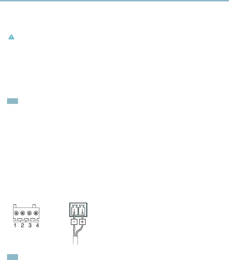
Power connector - 2-pin terminal block for power input.
I/O connector
DC power input
Note
For technical specific
ations, see page 54.
I/O terminal connector - Use in applications for e.g. motion detection, event triggering, time lapse recording and alarm notifications.
In addition to an auxiliary pow e r and a GND pin, the I/O terminal connector provides the interface to:
• Digital output
— For connecting external devices such as relays and LEDs. Connected devices can be activated by
the VAPIX® Application Prog ramm ing Interface, output buttons on the Live View page or by an Action Rule. The
output will show as active (shown under System Options > Ports & Devices) if the alarm device is activated.
6

AXIS P1344 Network Camera
Hardware overview
• Digital input — An alarm input for connecting devices that can toggle between an open and closed circuit, for
example: PIRs, door/window contacts, glass break detectors, etc. When a signal is received the state changes and
the input becomes active (shown under System Options > Ports & Devices).
Note
The I/O connector is connected to the housing (fan/heater) on delivery, an d will trigger an input port eve nt to indicate
a fan or heater error when activated. See Events, on page 33 for information on how to set up an event.
Function Pin Notes
Specifications
GND
1
Ground
3.3 V DC Power
2
Can be used to power auxiliary equipment.
Note: This pin can only be used as power out.
Max load = 50 mA
Digital Input
3
Connect to GND to activate, or leave floating (unconnected)
to deactivate.
0to+40VDC
Digital Output
4
Internal connection to ground when activated, floating
(unconnected) when deactivated. If used with an inductive
load, e.g. a relay, a diode must be connected in parallel with
the load, for protection against voltage transients.
Max load =100 mA
Max voltage = +40 V DC
3.3 V max 50 mA
1
2
3
4
LED indicators
LED
Color
Indication
Green
Steady for conne
ction to a 100 MBit/s network. Flashes for network activity.
Amber
Steady for connection to a 10 MBit/s network. Flashes for network activity.
Network
Unlit No network connection.
Green Steady green for no rmal operation.
Amber
Steady during startup and when restoring settings.
Status
Red
Slow flash for failed upgrade.
7

AXIS P1344 Network Camera
Hardware overview
Green
Normal op eration.
Power
Amber
Flashes green/amber during firmware upgrade.
Note
• The Status LED can be configured to be unlit during normal operation. To configure, go to Setup > System Options >
Ports & Devices > LED. See the online help for more in forma tion.
• The Status LED can be configured to flash while an event is active.
• The S tatus LED can be configured to flash for identifying the unit. This can be done under Setup > System Options >
Maintenance.
Status LED when using Focus A ssistant
Status Color
Indication
Green
Focus Assistant is enabled
The lens is optimally adjusted
Amber The camera has been moved, or an object has been inserted in front of the lens. Exit and
restart the Focus Assistant.
The lens is less optimally ad jus ted
Red The camera has been moved, or an object has been inserted in front of the lens. Exit and
restart the Focus Assistant.
The lens is poorly adjusted
Replacing the lens
It is possible to use optional lenses for the Axis product.
To replace the lens:
1. Disconnect the iris cable.
2. Unscrew the standard lens.
3. Attach and screw on the new lens.
8

AXIS P1344 Network Camera
Accessing the product
Accessing the product
To install the Axis product, refer to the Installa tion Guide supplied with the product.
The product can be used with most operating systems and browsers. The recommended browsers are Internet Explorer with Windows,
Safari with Macintosh and Firefox with other operating systems. See Technical Specifications, on page 54.
Note
• To view s treaming video in Internet Explorer, allow installation of AXIS Med ia Control (AMC) when prompted.
• QuickTime
TM
is also supported for viewing H.264 streams and for audio.
• If your computer restricts the use of additional software components, the product can be configured to use a Java
applet for viewing Motion JPEG.
• The Axis product includes (1) H.264 de code r license for viewing video streams and (1) AAC audio license. These licenses a re
automatically installed with AMC. The administrator can disable the installation of the decoders, to prevent installatio n of
unlicensed copies.
Access from a browser
1. Start a browser (Internet Explorer, Firefox, Safari).
2. Enter the IP address or host name of the Axis product in the browser’s Location/Address field. To access the product from a
Macintosh computer (Mac OS X), click on the Bonjour tab and select the product from the drop-down list.
If you do not know the IP address, use AXIS IP Utility to locate the product o n the network. For more information on how to
discover and assign an IP address, refer to the Installation Guide.
3. Enter y our user name and password. If this is the first time the product is accessed , the root password must first be
configured; for instructions see Set the root password, on page 10.
4. The product’s Live View page appears in your browser.
Note
The layout of the Live View page may have been customized to meet specificrequi
rements. Consequently, some of the
examples and functions featured here may differ from those displayed in your own Live View page.
9

AXIS P1344 Network Camera
Accessing the product
Access from the Internet
Once connected, the Axis product is accessible on your local network (LAN). To access the product from the Internet you must
configure your network router to allow incoming data traffic to the product. To do this, en able the NAT-traversal feature , which
will attempt to automatically configure the router to allow access to the product. This is enabled from Setup > System Options >
Network > TCP/IP Ad vanced.
For more information, please see NAT traversal (port mapping) for IPv4, on page 42.SeealsoAXISInternetDynamicDNSServiceat
www.axiscam.net For T echnical notes on this and other t opics, v isit the Axis Support web at www.axis.com\techsup
Set the root password
To gain access to the Axis product, you must set t he pa ssword for the default administrator user root. This is done in the Configure
Root Password dialog, which appears when the product is accessed for the first time.
To prevent network eavesdropping, the root password can be set via an encrypted HTTPS connection, which requires an HTTPS
certificate. HTTPS (Hypertext Tra
nsfer Protocol over SSL) is a protocol used to encrypt traffic between web browsers and servers. The
HTTPS certificate ensures encrypted exchange of information.
To set the password via a stand ard HTTP connection, enter it directly in the first dialog.
To set the password via an encrypted HTTPS connection, follow these steps:
1. Click Create self-signed certificate.
2. Provide the req uested information and click OK.Thecertificate is created and the password can now be set securely. All
traffic to and from the product is encrypted from this point on.
3. Enter a password and then re-enter to confirm the spelling. Click OK. The password has now been configured.
10

AXIS P1344 Network Camera
Accessing the product
Note
• The default administrator user name root is permanent and cannot be deleted.
• If the password for root is lost, the product must be reset to the factory default settings. See Reset to factory default
settings, on page 47.
The Live View page
If the Axis product has been customized to meet specific requirements, not all the items described be low wi ll appea r in the Live View
page. The following provides an overview of each available button.
Controls on the Live View page
Click View siz e to scale the image down to 800 pixels wide or to full scale. Only available in MJPEG.
The Stream Profile drop-down list allows you to select a custom
ized or pre-pro grammed stream profile. Stream
profiles are configured under Video & Audio > Stream Profiles.SeeStream Profiles, on page 19.
Click Pulse to activate the output for a defined period of time, such a s s w itching on an external light for 20 seconds.
Click the Active/Inactive buttons to manually start and stop a connected device — e.g. switch an external light
on and off.
The Manual Trigger button can trigger an event directly from the Live V iew page. The button is con figured under
Live View Config > Action Buttons.
11
AXIS P1344 Network Camera
Accessing the product
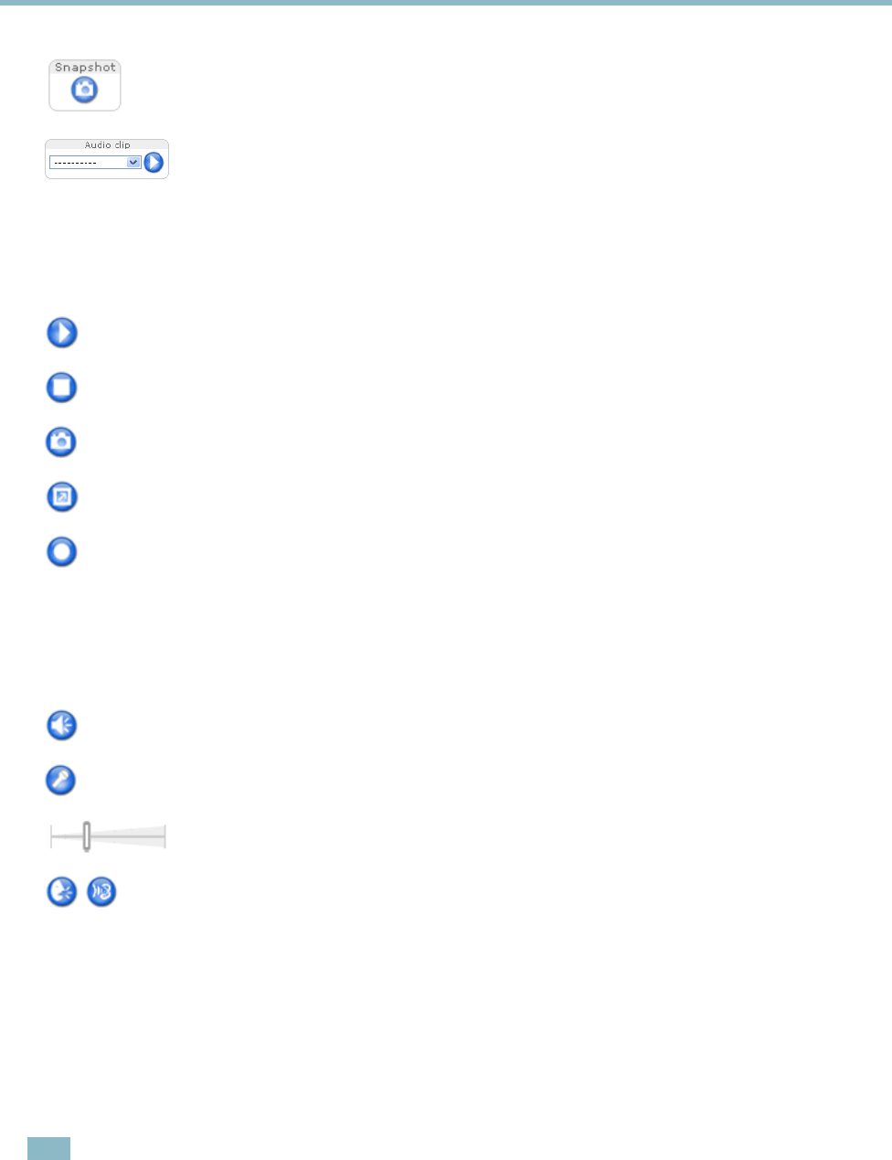
Click Snapshot to save a snapshot of the video image. Right-click the video image to save it in JPEG format on y our
computer. This button is primarily intended for use wh en the AXIS Media Control viewer toolbar is not available.
Enable this button from Live View Config > Action Buttons.
The Audio clip drop-down list allows you to play an audio clip from the Live View page. Select the audio
clip and click the Play button.
AXIS Media Control viewer toolbar
The AXIS Me d ia Control vie wer toolbar is available in Internet E xplorer only. See AXIS Media Control (AMC), on page 14 for m ore
information. The toolbar d ispl ays the following butto ns:
The Play button connects to the Axis product and starts playing a media stream.
The Stop button stops the media stream.
The Snapshot button takes a snapshot of the video i mage. The location where the image is saved can be specified
in the AMC Control Panel.
Click the View Full Screen button and the video image will fill the entire screen. Press ESC (Escape) on the computer
keyboard to cancel full screen view.
The Record button is used to record the current video stream. The lo cation where the recording is saved can be speci fied
in the AMC Control Panel.
AMC Audio controls
AMC audio buttons control the speakers and micro phone connected to the client computer. The buttons are only visible when
audio is enabled.
Speaker button — Click to turn the speakers on or off.
Microphone button – Click to mute or unmute the microphone. In Simplex - Network Camera speaker only mode,
click this button to stop sending audio to the product.
Use the slider to control the volume of the speakers and the microphone.
Half-duplex mode
The Talk/Listen button is used to switch between sending and receiving audio. The button can be configured
from the A udio tab in the AMC Control panel:
• Push-To-Talk m ode: Click and hold the button to talk/send. Release the button to listen.
• Toggle mod e: Click once to s witch between talking and listening.
Simplex – Network Cam era speaker only mode
To send audio, the Talk and Micro phone buttons must both be enabled. Click either button to stop audio
transmission.
PTZ Controls
The Live View page also displays Pan/Tilt/Zoom (PTZ) controls. The administrator can enable/disable controls for specified users under
System Options > Security > Users.
Note
These controls are ava ilable if digital PTZ is enabled in the selected view area, see View Area, on page 21.
12
AXIS P1344 Network Camera
Accessing the product
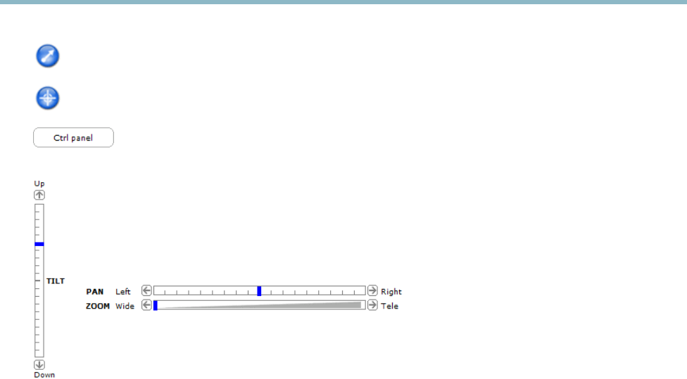
Click the Emulate joystick mode button and click in the image to m o ve the camera view in the direction of the
mouse pointer.
Click the Center mode button and click in the image to center the camera view on tha t pos ition.
Click the Ctrl panel button to open the PTZ control panel which provides additional PTZ controls.
User-defined buttons can also appear in the Co ntrol panel. See Controls, on page 28.
Pan and Tilt bars – Use the arrows to pan and tilt the camera view, or click on a position on the bar to steer the
camera view to that position.
Zoom bar – Use the arrows to zoom in and out, or click on a position on the bar to zoom to that position.
The PTZ controls can be disabled under PTZ > Advanced > Controls,seeControls, on page 28.
13

AXIS P1344 Network Camera
Media streams
Media streams
The Axis product provides several audio and video stream formats. Your requirem ents and the properties of your network will
determine the type you use.
The Live View page in the product provides access to H.264 and Motion JPEG video streams, audio streams and to the list of available
stream profiles. Other applications and clients can access video and audio streams directly, without going via the Live View page.
How to stream H.264
The video compression standard H.264 makes good use o f bandwidth, and can provide high quality video streams at less than 1 M bit/s.
Deciding which combination of protocols and method s to u se depends on your viewing requirem ents, and on the properties of
your network. The available options in AXIS Media Control are:
Unicast RTP
This unicast method (RTP over UDP) is used
for live unicast video, especially when it is
important to always have an up-to-date video
stream, even if some images are dropped.
RTP over RTSP
This unicast method (RTP tunneled over RTSP)
is useful as it is relatively s imple to configure
firewallstoallowRTSPtraffic.
RTP over RTSP over HTTP
This unicast method can be u sed to traverse
firewalls. Firewalls are commonly con figured to
allow the HTTP protocol, thus allowing RTP to
be tunneled.
Unicasting is used for video-on-demand
transmission so that there is no video traffic
on the network until a client connects and
requests the stream.
Note that there are a maximum of 20
simultaneous unicast connections.
Multicast RTP
This method (RTP o ver UDP) should be used for live multicast video. The video stream is al
ways
up-to-date, even if some images are dropped.
Multicasting provides the most efficient usage of bandwidth when there are large numbers of
clients viewing simultaneously. A multicast cannot however, pass a network ro
uter unless the
router is configured to allow this. It is not possible to multicast over the Internet, for example.
Note also that all multicast viewers count as one unicast viewer in the maximum total of 20
simultaneous connections.
AXIS Media Control negotiates with the Axis product to d etermine the transport protocol to use. The order o f priority, listed in the
AMC Control Panel, can be chang ed and the opti
ons disa bled, to s u it specific requirements.
Note
H.264 is licensed technology. The Axis product includes one H.264 viewing c lie nt license. Installing additional unlicensed
copies of the client is prohibited. To purchase additional licenses, contact your Axis reseller.
MJPEG
This format uses s
tandard JPEG still ima ges for the video stream. These images are then displayedandupdatedataratesufficient
to create a stream that shows constantly updated motion.
The Motion JPEG stream uses considerable amounts of bandwidth, but provides excellent image qualityandaccesstoeveryimage
contained in the stream. The recommended method of accessing Motion J PEG live video from the Axis product is to use the AXIS
Media C
ontrol in Internet Explorer in Windows.
AXIS Media Control (AMC)
AXIS Media Control (AMC) in Internet Explorer in Windows is the re comme nded method of accessing live video from the Axis product.
14

AXIS P1344 Network Camera
Media streams
TheAMCControlPanelcanbeusedtoconfigure various video and audio settings. Please see the AXIS Media Control User’s
Manual for more information.
The AMC Co ntrol Pane l is automatically installed on first us e, after which it can be configured. Open the AMC Control Panel from:
• Windows Control Panel (from the Start menu)
• Alternatively, right-click the vi deo image in Interne t Explorer and click Settings.
Alternative methods of accessing the video stream
You can also access video and images from the Axis product in the following ways:
• Motion JPEG server push (if supported by the client, Firefox, for example). This option maintains an open HTTP connection
to the browser and sends data a s and when required, for as long as required.
• Still JPEG images in a browser.Enterthepathhttp://<ip>/axis-cgi/jpg/image.cgi
• Windows M edia Player. This requires AXIS Media Control and the H.264 decoder to be installed. The following paths
can be used:
-UnicastviaRTP:axrtpu://<ip>/axis-media/media.amp
- Unicast via R TSP: axrtsp://<ip>/axis-media/media.amp
- Unicast via R TSP, tunneled via HTTP: axrtsphttp://<ip>/axis-media/media.amp
-Multicast:axrtpm://<ip>/axis-media/media.amp
• QuickTime
TM
. The following paths can be used:
- rtsp://<ip>/axis-media/media.amp
- rtsp://<ip>/axis-media/media.3gp
15

AXIS P1344 Network Camera
Media streams
Note
• <ip>= IP addess
• The Axis product supports QuickTime 6.5.1 and later.
• QuickTime adds latency to the video stream.
• It may be possible to use other players to view the H.264 stream using the paths above, although Axis does not guarantee
this.
Accessing audio streams
The Live View page provides access to audio through AXIS Media Control; in ad dition au dio can b e accessed in the following ways:
• VAPIX® Application Programming Interface (API) For more information, visit www.axis.com/developer
• Windows Media Player supports simplex audio. The following p aths can be used:
-UnicastviaRTP:axrtpu://<ip>/axis-media/media.amp
- Unicast via R TSP: axrtsp://<ip>/axis-media/media.amp
- Unicast via R TSP, tunneled via HTTP: axrtsphttp://<ip>/axis-media/media.amp
-Multicast:axrtpm://<ip>/axis-media/media.amp
• QuickTime
TM
supports G.711 and AAC audio encoding. The following paths can be used:
- rtsp://<ip>/axis-media/media.amp
- rtsp://<ip>/axis-media/media.3gp
•TheJava applet supports simplex audio with G.711 encoding.
16

AXIS P1344 Network Camera
Setting up the product
Setting up the product
The Axis product can be configur ed by users with a dministrator or operator rights. Cl ick Setup in the top right-hand corner of
theLiveViewpage.
• Administrators have unrestricted access to all settings.
• Operators have access to all settings except System O ptio ns
See also the online help
.
Basic Setup
Basic Setup provides shortcuts to the settings thatshouldbemadebeforeusingtheAxisproduct:
1. Users. See p age 38.
2. TCP/IP. See pa ge 40.
3. Date & Time. See page 39.
4. Video Stream. See page 18.
5. Focus. See page 22
6. Audio Settings. See page 22.
The Basic Setup menu can be disab led from System Options > Security > Users.
17

AXIS P1344 Network Camera
Video and Audio
Video and Audio
The video and audio settings c a n be used to optimize video a nd audio quality. You ca n configure the following:
• Video stream settings. See page 18.
•Streamprofiles. See page 19.
• Camera settings. See page 2 0.
•Viewarea.Seepage 21.
• Overlay image. See page 21.
•Privacymask.Seepage 22.
•Focus.Seepage 22.
• Audio settings. See pag e 22.
• Audio clips. See page 24.
Video Stream
You can define the following video stream settings from Video & Audio > Video Stream:
•Image.Seepage 19.
• H.264. See page 19.
•MJPEG.Seepage 19.
Pixel Counter
The pixel counter shows the number of pixels in an area of the image. The pixel counter is useful in situations where there is a
requirement that the image is a certain size, for e xample in face recognition.
The pixel counter can be accessed from:
18

AXIS P1344 Network Camera
Video and Audio
• Video & Audio > Video Stream.UnderPreview, click Open and select the Show pixel counter option to e nable the
rectangle in the image. Use the mouse to mo ve and resize the rectangle, or enter the number of pixels in the Width
and Height fields and click Apply.
• Video & Audio > Focus.SelecttheShow pixel counter option to enable the rectangle in the image. Use the mouse to
move and resize the rectangle, or enter the number of pixels in the Width and Height fie lds a n d click Apply.
• The Live View page in Internet Explorer in W indows. Right-click in the imag e and select Pixel counter.Usethemouse
to move and resize the rectangle.
Image
You can modify the image resolution and compression, and rotate the image from the Image tab (Video & Audio > Video Stream).
The image can also be mirrored fro m the Image tab.
Setting the compression level affects the image quality and bandwidth; the lower the compression, the higher the image quality
with higher bandwidth requirements.
To avoid bandwidth problems on the netw ork, you can limit the frame rate allowed to each viewer. The maximum frame ra te can be
set to Unlimited, or you can limit the frame rate to a value.
An image or text can be superimposed over the image as overlay. See Overlay, on pag e 21.
Save your settings before they can take effect.
H.264
H.264, also known as MPEG-4 Part 10/AVC, is a video compression standard that provides high quality video streams at low bit rates.
An H.264 video s tream consists of diffe re nt types of frames such as I-frames, P-frames and B-frames. An I-frame is a complete image
whereas P-frames and B-frames only contain the differences from p re vious/future fram
es.
The GOV length is the number of frames between two consecutive I-frames. Increa
sing the GOV length may save considerably on
bandwidth requirements in some cases, but may also have an adverse affect on image quality.
ThebitratecanbesetasVariable Bit Rate (VBR) or Constant Bit Rate (CBR). VBR adjusts the bit rate according to the image
complexity, using up more bandwidth for incre as ed activity in the ima ge, a nd le ss for lo wer ima ge a c tivity. CB R a llow s you to s et a
fixed Target bit rate that consumes a predictable amount of bandw
idth. As the bit rate wo uld usuall y nee d to incre ase for increased
image activity, but in this case cannot, frame rate and image quality are affected negatively. To partly compensate for this, it is
possible to prioritize either frame rate or image quality. Not setting a priority means that frame r ate and image quality are equally
affected. You must save your settings befo
re they can take effect.
The current bit rate can be set to appe
ar as text overlay. To do this, select the Include text check box option under Overlay Settings
and enter the code #b in the field.
MJPEG
Sometimes the image size is large due to low light or complex scenery. Adjusting the maximum frame size helps to control the
bandwidth and stor
age used by the Motion JPEG video stream in these situations. Setting the frame size to the Default setting
provides consistently good image quality at the expense of increased bandwidth and storage usage in low light. Limiting the frame
size optimizes bandwidth and storage usage, but may give poor image quality. To prevent increased bandwidth and storage usage,
the maxim um fr
ame size should be set to an optimal value.
Stream Profiles
There are four pre-programmed stream profiles available for quick set up. The settings for these can be adjusted. New customized
profiles can also be created. Each profile has a descriptive name, indicating its purpose.
•Thestreamprofiles can be accessed from the Stream profile drop-down list in the Live View page.
• To add, copy, modify, and remove stream profiles go to Video & Audio > Stream Profiles.
19

AXIS P1344 Network Camera
Video and Audio
• To select the default stream pro file go to Live View Config > Stream Profile and choose the profile from the drop-down list.
For more information see the online help
on this page.
Camera Settings
The Video & Audio > Camera Settings page provides access to advanced image settings for the Axis product.
Image Appearance
Increasing the Color level increases the color saturation. The value 100 gives maximum color saturation. The value 0 gives a
black and white i mage.
The image Brightness can be adjusted in the range 0–100, where a higher value produces a brighter image.
Increasing the Sharpness can increase bandwidth usage. A sharper image might increase image noise especially in low light
conditions. A lower setting reduces image noise, but the whole image will appear less sharp.
The Contrast change s the relative difference between light and dark. It can be adjusted using the slidebar.
White balance
White balance is used to make colors in the image appear the same regardless of the color temperature of the lig ht source. The Axis
product can be set to automatically identify the light source and compensate for its color. Alternatively, select the type of light
source from the drop-down list. For a description of each available setting, see the online help
.
Wide Dynamic Range
Wide dynamic r ange can improve the exposure when there is a considerable contrast between light and dark areas in the image. In
intense backlight co nditions , enable WDR. Disable WDR I n low light cond itions for optimal e xpo sure.
Note
This se tting is only possible when using autom atic exposure control.
Exposure Settings
Configure the exposure settings to suit the image qual
ity requirements in relation to lighting, frame rate and bandwidth
considerations.
Exposure value - Click in the bar to fine-tune the expo sure.
Exposure control - These settings is used to adapt to the amount of light used. Automatic is the default settings can be used in most
situations. The shutter speed is automatically set to produce optimum image quality. Flicker-free 50 or 60 Hz is used to remove
flicker which can be caused by
fluorescent a nd other light sources. The Hold current option l ocks the current exposure settings.
Enable Backlight compe
nsation - Enable this option if a bright spo t of light, for example a light bulb, causes other areas in
the image to appear too dark.
Exposure zones - This settings determines which part of the image is used to calculate the exposure. For most situations, the Auto
setting can be used. For particular requirement, select a predefined area.
Exposure priority - When Motion is prioritized and maximum Shutter time is set to a small val ue, motion blur in the image is
minimiz
ed. This can be useful for recognition of mo ving objects such as people and vehicles. However, prioritizing motion may cause
an increase in ima ge noise, especially in low light situa tions. When Low noise is prioritized and Gain is set to a small value, image
noise is minimized. The file size is reduced, which can be useful if storage space or bandwidth is limited. However, prioritizing low
noi
se may result in a very dark image, especially in low light situations.
20

AXIS P1344 Network Camera
Video and Audio
Day/Night
The IR cut filter prevents infrared (IR) light from reaching the image sensor. In poor lighting conditions, for example at night, or
when using an IR lamp, set the IR cut filter to Off. This incr ea ses light s ensitivity and allows the product to “see” infrared light. The
image is shown in black and white when the IR cut filter is off.
If using automatic Exposure control,settheIRcutfilter to Auto to automatically switch between On and Off accordingtothe
lighting conditions.
Iris configuration
Iris configuration shows the current configured iris type. Do not change the iris configuration unless the lens has been chang ed,
see Replacing the lens, on page 8 .
Iris adjustment
Select Enable automatic iris adjustment to automatically com pensate for chang ing light conditions. This option is not available
if a fixed iris is used.
View Area
A v iew area is a cropped part of the full view. The view area is treated as a video source in Live View and has its own video
stream and PTZ settings.
To enable a view area, go to Video & Audio > Camera Settings and select Enable View Area.
When setting up a view area it is recommended that the video stream resolution is the same size as or s maller than the view a re a
size. Setting the video stream resolution larger than the view area size implies digitally scaled up video after sensor capture,
requiring more bandwidth without adding image information.
To configure the view area:
1. Go to Video & Audio > View Area.
2. Select an Aspect ratio and a Video stream resolution.
3. A new view area covers the whole image. Usethemousetomoveandresizetheviewarea.
4. Select Enable PTZ to enable digital PTZ for the view area.
5. Click Save to save the settings.
To modify the view area, modify the settings a s required. Click Save.
Tip:
• The PTZ functionality is useful during installation of the Axis product. Use a view area to crop out a specificpartof
the full view.
Overlay
Overlays
can be used to provide extra information and are superimposed over the vid eo image. With overlay text it is possible to
include date and time or view the current bit rate as overlay text.
To include the current bit rate as overlay text go to Video & Audio > Video Stream > Overlay Settings,selecttheInclude text check
box option, a nd enter the code #b in the field. See the online help
for supported formats.
Overlay image
An overlay ima ge can be us ed to provide e x tra information, or to mask a part of the video image.
21

AXIS P1344 Network Camera
Video and Audio
To use your own image, such as a logo, first upload the image to the Axis product. Go to Video & Audio > Overlay Image, click
Browse to locate the file and then click Upload.ThefilecanthenbeselectedfromtheUse ove rlay image drop-down list.
To place an overlay image at specificcoordinates,gotoVideo & Audio > Video Stream and select the Include overlay image at
coordinates check box option and enter the X and Y coordinates.
For more information see the online help
Privacy Mask
A privacy mask is an area of solid color that prohibits users fro m viewing parts of the monitored area. Privacy masks canno t be
bypassed via the VAPIX® Application Pro gramming Interface (API).
The Privacy Mask List (Video & Audio > Privacy Mask) shows all the masks that are currently configured in the Axis product and
indicates if they are enabled.
You can add a new mask, re-size the mask with the mouse,chooseacolorforthemask,andgivethemaskaname.
For more information, see the online help
Focus
You can focus the Axis pro duct under Video & Audio > Focus. For most applications, the adjustments on the Basic tab are sufficient.
If required, additional adjustments can be m ade on the Advanced tab. Before focus ing, alw ays click Open iris to open the iris to its
maximum. This gives the smallest depth of field and thus best conditions for correct focusing. Click Enable iris when finished focusing.
Basic
Follow the on-screen instructions on the Basic tab to adjust zoom and focus. The pixel counter is used to d etermine the num ber of
pixels in an area of the image, for example to e nsure that the image size fulfills s
pecific r equirements. To position the pixel counter,
click o n the text and drag the window to the desired position.
Note
• The back focus (step 2) should only be reset if the camera has been focused previously.
• Set focus as precisely as possible using the focus puller on the lens (step 3) before starting the automatic fine-tuning
(step 4).
• If the camera is placed so that it is difficult to look at the image and move the pullers at the same time, you can use the
Focus Assistant to focus the camera; for ins tructions , se e the Installation Guide supplied with the product.
Advanced
The tools on this page can be used to find the optimal focus position. Always open the iris before focusing and enable it when finished
focusing. Focus is measured in th
epartoftheimagecoveredbytheFocus window. Use the mouse to move and resize the window
and then click Fine-tune focus automatically. If needed, click in the Focus position baroronthearrowsattheendsofthebar,to
further adjust the focus. T h e buttons < and > move the focus position one step in either direction. The buttons << and >> move the
focus position multip
le steps in e ithe r direction. Clicking on the bar sets focus to tha t position. If the camera is not focused after
completing the above instructions, try the Full range focus scan. The scan, which can take several minutes, transforms the focus
position bar to a graph where p eaks indicate the best focus positions. Click in the gra ph to set focus to the desired position.
Audio Settings
The audio functionality for each video stream is enabled under Video & Audio > Video Stream > Audio.
Audio Channels
Select the type of audio transmission from the Audio mode: drop-down list (Video & Audio> Audio Settings). The different types are:
Full duplex - Simultaneous two-way audio allowing you to transmit and receive audio (talk and listen) at the same time. There is no
echo cancellation; i f feedback loops appear, try moving the microphone or the speaker.
22

AXIS P1344 Network Camera
Video and Audio
Half-duplex - Audio can b e transmitted in both directions between the Axis pro duct and the client computer, b ut only in one
direction at a time. You must actively receive sound using the Talk/Listen button visible in the Live View page (see AXIS Media
Control viewer toolbar). In Push-To-Talk mode, click and hold the button to s peak and release it whe n done. In Toggle mode, click
once to switch between speaking and listening. The Talk/Listen mode is configured from the Audio tab in the AMC control panel
(see AXIS Media Control on page 14).
Simplex - Network C amera speaker only - Audio is transmitted from the client to the Axis product and played by the speaker
connected to the product. To send audio, the Talk and Microphone buttons in the AMC toolbar must both be enabled. Click either
button to stop audio transmission.
Simplex - Network Camera m icrophone only - A udio captured by the microphone connected to the Axis product is transmitted from
theproducttooneormoreclients.
For more information about these settings, please see the online h elp
.
Audio Input
An external microphone or a line source can be connected to the product’s Audio-in connector. Config u re the audio input settings
under Video & Audio > Audio Settings.
Source - Select Microphone for an external microphone or Line for a Line in device, e.g. an audio mixer for multiple microphones or
a microphone with a built-in amplifier.
Microphone power - The Enable microphone power option provides DC power for an external microphone. Microphone power should
only be used with microphones that have no battery and when using the internal microphone. This setting should not be enabled
when using a dynamic or battery powered microphone. Microphone power will not harm the microphone; if you are uncertain, try
switching it off and on. To use a professional microphone requiring 48V phantom power, you need an external p ower supply and a
balanced-unbalanced converter (audio transfor mer) in betwee n.
Input gain - Control the volume (dB Full Scale) of the audio input. If the sound is too low, choose a higher dB, to amplify the
sound. If the sound is too high, choose a lower dB. The Level bar gives a visual representation of the audio signal level in dB
relative to the full-scale input level.
• Green — the signal is at a good level.
• Yellow — the signal is becoming d istorted.
• Red — the signal is distorted.
Encoding - Select digital audio encoding format.
• AAC requires a license for both encoding and decoding. AAC is the least complicated and most widely used codec.
If achieving the best possible audio qua
lity is a priority, AAC is the recommended codec to use. An AAC lice n se
is included in the Axis product.
• G711
• G726
Sample rate - The number of times per second the sound is sampled. A higher sample rate will provide bette r audio quality, but
also requires a greater bandwidth.
Bit rate
- Set the required bit rate depending on the selected encoding. A higher bit rate will give bette r a udio quality. A lower bit
rate may have latency or delay, but will require less bandwidth.
For more information about these settings, please see the online h elp
.
23

AXIS P1344 Network Camera
Video and Audio
Audio Output
An external speaker can be connected to the product’s Audio-out connector. The output can be used with high impedance
headphones or connected to another amplifier with speakers.
Configure the audio output settings under Video & Audio > Audio Settings.
Output gain - Control the volume (dB Full Scale) of the line audio output. If the sound is too low, choose a higher dB. If the
sound is to o high, choose a low e r dB.
Audio Clips
An audio clip is a sound file that can be played either when an event occurs or manually from the Live View page. Audio clips can
be uploaded to the product or recorded by a microphone connected to the product.
You can add, play, download, modify and remove audio clips from Video & Audio > Audio Clips. For more information see the
online help
.
Note
Audio clips cannot be used if the product’s aud io functionality is e nabled. The audio functionality is enabled on the Audio
tab under Video & Audio > Video Stream.
24

AXIS P1344 Network Camera
Live View Config
Live View Con fig
You can customize the Live View page and alter it to suit your requirements. It is possible to define the fo llowing features of
theLiveViewpage.
•StreamProfile. See page 19.
• Default Viewer for Browser. See page 25.
• Viewer Settings. See page 26.
• Action Buttons. These are the buttons described in Controls on the Live View page, on page 11.
•UserDefined Links. See page 26.
• Output Buttons. See page 26.
Default viewer for browsers
From Live View Config > Default Viewer select the default method for viewing video images in your browser. The product attempts
to show the video images in the selected video format and v iewer. If this is not possible, the product overrides the settings and
selects the
best available combination.
25

AXIS P1344 Network Camera
Live View Config
Browser Viewer Description
AMC
Recommended viewer in Internet Explorer (H.264/Motion JPEG)
QuickTime
H.264
Java applet
A slower imaging alternative to AMC (Motion JPEG). Requires one of the
following installed on the client:
• JVM (J2SE) 1.4.2 or higher
• JRE (J2SE) 5.0 or higher
Windows Internet Explorer
Still image Displays still images only. Click the Refresh button in your browser to view a
new image
Server Push
Recommended viewer for other browsers (Motion JPEG).
QuickTime
H.264
Java applet
A slower imaging altern ative to Server Push (Motion JPEG only).
Other browsers
Still image Displays still images only. Click the Refresh button in your browser to view a
new image
For more information, please see the online help .
Viewer Settings
Options for the viewer are configured under Live View Config > Viewer Settings.
•TheShow viewer toolbar option will display the AX IS Media Control (AMC) or the QuickTime viewer toolbar under the
video image in your browser.
• H.264 decoder installation. The administrator can disable installation of the H.264 decoder included with AXIS Media
Control. This is used to prevent installation of unlicensed copies. Further decod er licenses can b e purchased from your
Axis reseller.
•SelectShow crosshair in PTZ joystick mode to enable a cross that will indicate the center of the image in PTZ joystick mode.
•SelectUse PTZ joystick mode as default to enable joystick mode. The mode can be changed temporarily from the PTZ
control panel.
• You can enable recording from the Live View page. The recordings are saved to the location specified in the AMC Control
Panel. See AXIS Media Control (AMC), on page 14.
User Defined Link s
To display user-defined links in the Live View page, select the Show custom link option, give the link a name and then enter the URL
to link to. When defining a web link do not rem ove the 'http://' from the URL address. Custom links can be used to run scripts or
activate external devices connected to the product, or they can link to a web p age . Custo m links defined as cgi links w ill run the
script in the background, in a hidden frame. D efining the link as a web link will open the link in a new wind ow.
Output Buttons
An output on the Axis product can be controlled directly from the Live View page, by enabling the display of output buttons. To
display the output buttons in the Live View page, select the type of control to use for the port from the drop-down list under
Live View Config > Output Buttons:
• Pulse activates the output for a defined period of time. The pulse time can be set as short as 1/100 second, and as
long as 60 seconds
• Active/Inactive displays two buttons (on/off). The output ports must first be configured under System Options> Ports &
Devices > I/O Ports.SeeI/O Ports, on page 45.
26

AXIS P1344 Network Camera
PTZ (Pan Tilt Zoom)
PTZ (Pan Tilt Zoom )
Preset Positions
A preset position is a predefined view that can be used to quickly steer the camera to a specific location. Preset positions can
be accessed in several ways:
• By selecting the preset from the Preset positions drop-down list in the Live View Page.
• When setting up action rules. See page 33.
• When setting up Guard Tour. See page 27.
To add a preset position:
1. Go to PTZ > Preset Positions.
2. Use the pan, tilt and zoom controls to steer the camera view to the desired position.
3. Enter a descriptive name in the Current position field.
The product can be configured to return to the Home position w hen the PTZ functionality has been inactive for a specified length
of time. Enter the length of time in the field and click Save. Set the time to zero to p re vent the product from automatically
returning to the H ome position.
To include the preset position name in the overlay text, go to Video & Audio,selectInclude overlay text and enter the modifier #P in
the field. For more information about modifiers, see File Naming & Date/Tim e Forma ts intheonlinehelp
.
Guard Tour
A guard tour displa ys the video stream from different preset positions, one-by-one, in a predetermined order or at random and for
config
urable time periods. The enabled guard tour will keep running after the user has logged off or closed the browser.
T
o add a guard tour:
1. Go to PTZ>GuardTourand click Add.
2. Enter a descriptive name.
3. Specify the pause length between runs.
27

AXIS P1344 Network Camera
PTZ (Pan Tilt Zoom)
4. Select an available pre se t pos ition and cl ick Apply.
6. Specify the View Time in seconds or minutes.
7. Specify the View order or select the Random view order check box option.
8. Click Save.
To mo dify or remove guard tours, go to PTZ>GuardTour, select the guard tour in the Guard T our L ist and click Modify/Remove.
For more information see the online help
.
Advanced
Controls
Panel Shortcut Command Buttons can be configured to provide direct access to commands issued via the VAPIX® Applicatio n
Programming Interface. T he buttons will be displayed in the PTZ control panel, which is available in the Live View page through
the Ctrl panel button, see page 12.
Note
Disabling PTZ controls will not affect preset positions. For example, if the tilt control is disabled, the product can still move to
preset positions that require a tilt movement.
28

AXIS P1344 Network Camera
Detectors
Detectors
Camera Tampering
Camera Tamper ing can generate an alarm whene ve r the camera is repositioned, or when the lens is covered, sprayed or severely
defocused. To send an alarm, for example an email, an action rule must be set up.
To configure tampering:
1. Go to Detectors > Camera Tampering.
2. Set the Minimum duration, that is, the time that must elapse before an alarm is generated. This ca n help prevent false
alarms for known conditio ns that affect the image.
3. Select Alarm for dark images if an al arm should be generated if l ights a re dimmed or turned off, or if the lens is sprayed,
covered, or rende red severely out of focus.
4. Click Save.
To configure the product to send an alarm when tampering occurs:
1. Go to Events > Action Rules.
2. Click Add to set u p a new action rule.
3. Enter a Name for the action rule.
4. Under Condition,selectDetectors from the Trigger list.
5. Select Tamperin g from the list of detectors.
6. Optionally, select a schedule and set additional conditions.
7. Select the action. To se nd an email, select Send Notification a
nd select a Recipient from the list of defined recipients.
Note
The While the rule is active op tion under Duration cannot be used with camera tampering, since camera tampering does not
have a duration and once it has been triggered it will not automatically return to its untrigge re d state.
For more information on actions rules, see Events, on page 33.
Motion Detection
Motiondetectionisusedtogenerateanalarmwhenevermovementoccurs(orstops)intheview.Upto10IncludeandExclude
windows can be configured:
• Include windows — target specific a reas within the whole video image
• Exclude windows —define areas within an Include window that should be ignored (areas outside Include windows
a
re automatically ignored)
Once configured, motion detection windows appear in the list of Detectors in Action rule setup. See Setting Up an Action Rule, on
page 33.
Note
Using the motion detection feature may decrease the product’s overal l performance.
29

AXIS P1344 Network Camera
Detectors
Set up motion detection
To set up a motion detection Include Window, follow these instructions:
1. Go to Detectors > Motion Detection.
2. Select the Configure Included Windows option and click New. Select the new window in the list of windows and enter
adescriptivename.
3. Adjust the size (drag the bottom right-hand corner) and the position (click on the text at the top and drag to the desired
position) o f the active window (window with red frame).
4. Adjust the Object Size, History and Sensitivity profile sliders (see Motion detectio n pa rameters f or details). Any detected
motion within an active window is indicated by red peaks in the Activity window.
5. Click Save.
To exclude parts of the include window, select the Configure Excluded Windows and position the exclude window within the
include window.
To delete an include or exclude window, s elect the window in the list of
windows and click Del.
Motion detection parameters
The parameters controlling motion detection are described in the table below:
Parameter
Object Size
History
Sensitivity
Description
Object size relative to window
size.
Object memory length.
Difference in lumi nance
between background and
object.
High level (100%)
Only very large objects trigger
motion detection.
An object that appears in
the window triggers motion
detection for a l
ong time
before it is considered as
non-moving.
Ordinary colored objects on
ordinary backgrounds trigger
motion detectio n.
Medium l
evel (50%)
A large difference in luminance
is required to trigge r motion
detection.
Low level (0%)
E
ven very small objects trigger
motion detection.
A
n object that appears in
the window triggers motion
detection only for a very short
time before it is considered as
non-moving.
Only very bright objects on
a dark background trigger
motion detectio n.
30

AXIS P1344 Network Camera
Detectors
Recommended values
5–15% 60–90% 75–95%
Default values
15% 90% 90%
Tips:
• To trigger on small objects or movements, use several small m otion detection windows rather than one large window
and select a low object size.
• To avoid triggering on small objects , sel ect a high object size.
• If no objects should appear in the Include Window, select a high history level. This will cause motion detection to trigger as
long as the object is present in the w indow .
• To only detect flashing light, select a low sensitivity. In other cases high sensitivity is recommended.
Audio detection
The Axis product can be configured to generate an alarm when audio rises ab ove or falls below the threshold v alue. The threshold
value can be set in the range 0–100 where 0 is the most s ensitive and 100 the l east sensitive.
1. Go to Detectors > Audio Detection.
2. Set the audio alarm level and click Save.
3. Go to Events > Action Rules and set up an action rule, se e Setting Up an Action Rule, on page 33.
Detected audio is indicated by colored peaks in the Activity indicator. An event is triggered when detected audio rises above or falls
below the threshold value, which is represented by the bar.
31

AXIS P1344 Network Camera
Applications
Applications
Third party applications can be uploaded to and installed on the Axis product. For information about available applications,
downloads, trials and licenses, go to www.axis.com/applications
To upload an a pplica tion, go to Applications > Overview, c lick Browse to locate the file and then click Upload Package. Click on the
uploaded application’s name to open the menu options Settings, License and About.Forconfiguration instructions, please r efer to
the documentation provided with the application.
Most applications need a license to run. To install the license, select the License menu option. If the product is connected
to the Internet, Automatic Installation appears in the web page. If the product is not connected to the Internet, go to
www.axis.com/applications to acquire a License key. You will need a license code and the product’s serial number (found on the label
and under System Options > Support > System Overview) to receive a license key.
Installed Applications lists installed applicati ons with information about the version and the ve ndor, the status of the application
(running or not running), and information about the license.
Use the Start and Stop buttons to start and stop the application.
To generate a log file f or the application, s elect the application a nd click Log .
Note
It is recommended to run one application at a time. Avoid running applications when motion detectio n is active.
32

AXIS P1344 Network Camera
Events
Events
The Axis product can be configured to p e rform actions when di fferent events occur, for example, start a recording when motion is
detected. The set of conditions that defines how and when the action is triggere d is called an Action Rule. The action rule w ill apply
at specific periods called Schedules. It is possible to specify how often the action rule will recur. This is called Recurrences.
Available Action Rule triggers include:
• Detectors, for example audio detection and motion detection, see Detectors, on page 29
• Input Signal — when the product’s I/O port receives a signal from an external device, such as a smoke detector or switch
• PTZ — when the product’s pan/tilt/z oom controls are activate d or w he n the v ie w stops at a preset position
• Storage — when a storage device is a vailable, locked or full
• System — when the pro duct is started
•Time,seeRecurrences, o n pag e 34
Possible actions include:
• Day/Night Vision Mode
• Output Port — activate an output to, for example, sound an alarm or lock a door
• Play Audio Clip
• Record Video — record video and save to a selected storage
•SendImagesandNotificatio ns — once recipients have been set up, a notification can be sent that an event has occurred
•StatusLED
Convert Eve nt Types to Action Rules
The internal Event Management system has been redesigned from firmware version 5.40. The legacy user Event Types in the
camera will continue to work but wi
ll not be visible in the user interface of the camera. The Event Ty pes need to be co nverted to
Action rules to become visible in the user interface.
To convert Event Types to Action Rules go to Events > Action Rules and click Convert.
Caution
This is not recomme
nded when using a VMS b ased on the old Event Management System.
Setting Up an Action Rule
An action rule defines the conditions that must be met for the product to perfo rm an action, f or example record video or send email
notifications. If multiple conditions are de fined, all must be met to trigger the action.
The follo wing example d escribes how to set up an action rule to send an email if there is m ovement in the product’s field o f view:
1. Go to Events > Action Rules and click Add.
2. Select the Enable rule option and enter a descriptive name for the rule.
3. Select Detectors from the Trigger drop-down list.
4. Select Motion Detection from the drop-down list. This optio n is only available if a motion detection window has been
configured, see page 30.
33

AXIS P1344 Network Camera
Events
5. Set one of the available pre-programmed time intervals from the Schedule drop-down list.
6. Select Send Notification from the Type drop-down list.
7. Select where to send the notification from the Re cipient drop-down list.
To add additional criteria, select the Additional conditions option. Add and select the desired options as described above. To prevent
an action from being triggered repeatedly, a Wait at least time can be set. Enter the time in hours, minutes and seconds, during
which the trigger should be ignored before the action rule can be activated again.
To copy, modify or remove an action rule , select the action rule in the Action Rule List and click Copy, Modify or Remove.
The recording Duration of some actions can be set to include time immediately before and after the event. Select Pre-trigger time
and/or Post-trigger time and enter the number of seconds. When While the rule is active is enabled and the action is triggered
again during the post-trigger time, the recording time will be extended with another post-trigger time period.
For more information, see the online help
.
Recipients
Recipients receive image files and notification messages. A recipient can be an FTP, HTTP or TCP server, a network share or an email
address. TCP servers are used for notification messages only.
To add a recipient:
1. Go to Events > Recipients and click Add.
2. Enter a descriptive name
3. Select a recipient Type.
4. Enter the information needed for the recipient type.
5. Click Test to test the connection to the recipient.
6. Click OK.
Schedules
An action can be s et up to occur on a schedule. Included i n the list are predefined schedules for after and during office hours,
weekdays or weekends.
To create a new schedule:
1. Go to Events > Schedules and click Add.
2. Enter a descriptive name and the information needed for a daily, wee kly, monthly or yearly s chedule.
3. Click OK.
To use the schedule in an Action Rule, select the schedule from the Schedule drop-down list in the Action Rule Setup page.
Recurrences
An action can be set up to recur a specific number of times in a period, for example every 2 minutes or every hour.
To set u p a recurrence:
1. Go to Events > Recurrences and click Add.
2. Enter a descriptive name and re curre nce p atter n .
34

AXIS P1344 Network Camera
Events
3. Click OK.
To use the recurrence in an A ction Rule, first select Time from the Trigger drop-down list in the A ction Rule Setup page and
then select the recurrence from the second drop-down list.
To modify or remove re currences, select the recurrence in the Recurrences List an d c lick Modify or Remove.
35

AXIS P1344 Network Camera
Recordings
Recordings
TheAxisproductcanbeconfigured to record video continuously or according to an action rule:
• To start a continuous recording, see page 36.
• To set up a ction rules, see page 33.
• To access recordings, see Record ing List, on page 36.
•Toconfigure came ra controlled storag e, see Storage, on page 44.
Recording List
Recordings made to the SD card and network share are listed on the Recordings > List page. The list shows each r ecording’s start
date an d time, duratio n and the event that triggered the recording.
To play or d ownload a recording , follow these steps:
1. Go to Recordings > List.
2. Use the fi lter to narrow the list of recordings. Enter the desired filter criteria and click Filter. Some filters may take
a long tim e to complete.
3. Select the recording.
4. Click Play to play the recording, or click Download to download the recording.
Multiple recordings can be downloaded at the same time. Select the recordings and click Download. The downloaded file is a zip file
containing a minimum of three files, of which the Matroska (mkv) files are the actual recordings. The recordings are time-stamped
with the date and time they were downloaded (that is, not the date the
recordings we re made).
Note
To play recordings in Windows Media Player, A XIS Matroska File Splitter must be ins talle d. AXIS Matroska File Splitter
can be downloaded from www.axis.com/techsup/software
For detailed recording and video information, select a recording and click Properties.
To remove a recording, select the r ecor ding and click Remove.
Continuous recording
The Axis product can be configured to continuously save video to an SD card or network share. To prevent the disk from becoming
full, it is recommended to configure the disk to automatically remove old recordings see Storage, on page 44.
To start a continuous recording, follow these steps:
1. Go to Recordings > Continuous.
2. Select Enabled.
3. Select from the S D card or network share from the Disk list.
4. Select a Stream profile to use for continuous recordings.
5. Click Save to save and start the recording.
36

AXIS P1344 Network Camera
Recordings
Note
If a new stream profile is selected while a recording is ongoing, the recording w ill be stopped and saved in the recording list
and a new recording with the new stream profile will s t art. All previous continuous recordings will remain in the recording
list until they are removed manually or thr ough automatic removal of old reco rdings .
37

AXIS P1344 Network Camera
System Options
System Options
Security
Users
User access control is enabled by default and can be configured under System Options > Security > Users. An administrator can
set up other users by giving them user names and passwords. It is also possible to allow anonymous viewer login, which means
that anybody may a ccess the Live View page.
The user list displays authorized users and user g roups (access levels):
Viewer - Access to the Live View page
Operator - Access to the Live View page and to all settings except System Options
Administrator - Unrestricted access to all settings; can add, modify and remove other users.
Under HTTP/RTSPPasswordSettings, select the type of password to allow. You may need to allow unencrypted passwords if there
are viewing clients that do not support encryption, or if you upgraded the firmware and existing clients support encryption but need
to log in again and be configuredtousethisfunctionality.
Under User Settings, select the Enable anonymous v iewer login option to allow anonymous users access to the Live View page.
Select the Enable anonymous PTZ control login to allow anonymous users access to the PTZ controls.
Deselect the Enable Basic Setup option to hide the Basic Setup menu. Basic Setup provides quick access to settings that should be
made before using the Axis product.
ONVIF
ONVIF (Open Network Vi d eo Interface Forum) is a global interface standard that makes it easier for e n d us ers, integrators, consultan ts,
and manufacturers to take advantage of the possibilities offered by network video technology. ONVIF enables interoperablity between
different vendor pro ducts, increased flexibility, red
uced cost and future-proof systems.
By creating a user you automaticall
y enable ONVIF communication. Use the user name and password with all ONVIF communication
with the product. For more information see www.onvif.org
IP Address Filter
IP address filtering is ena ble d on the System Options > Security > IP Address Filter page. Once enabled, the listed IP address are
allowed or denied acces
s to the Axis product. Select Allow or Deny from the li st and click Apply to enable IP address filtering.
The administr
ator can add up to 256 IP address entries to the list (a single entry can conta in multiple IP addresses).
HTTPS
The Axis product supports encrypted browsing using HTTPS. This is con figured on the System Options > Security > HTTPS page.
A self-signed cer tificate can be used until a Certificate Authority-issued certificate has been obtained. Click Create self-signed
certificate to ins tall a self-signed certificate. Although self-signed certificates are free and offer some protection, true security is only
implemented after the installation of a signed certificate issued by a Certificate Authority.
To obtain a signed certificate from an issuing Certificate Author ity, click Create Certificate Request. When the signed certificate
is returned, click Install signed certificate to import the certificate. The properties of any certificate request currently resident in
the product or installed can be viewed by clicking Properties.
To enable HTTPS in the Axis product, the HTTPS Connection Policy must be set for each user group.
For more information, see the online help
.
38

AXIS P1344 Network Camera
System Options
IEEE 802.1X
IEEE 802.1X is a standard for port-based Network Admissio n Control providing secure authentication of wired and wireless network
devices. IEEE 802.1X is based on EAP (Extensible Authentication Protocol).
To access a network protected by IEEE 802.1X, devices must authenticate themselves. The authentication is performed by a
third-party entity called an authentication s erver, typically a RADIUS server, examples of which are FreeRADIUS and Microsoft
Internet Authentication Service.
In Axis' implementation, the netw ork de vice and the authe n tication server authenticate themselves with the help of digital
certificates using EAP-TLS (Extensible Authentication Protocol - Transport Layer Security). The certificates are provided by an
Certification Authority (CA). You need:
•aCAcertificate to validate the identity of the authentication server
• a CA-signed client certificate and a private key to authenticate the network device.
To allow the netwo rk device to access a network protected by IEEE 802.1X:
1. Obtain a CA certificate, a client certificate and a client private key (contact your network administrator).
2. Go to Setup > System Options > Security > IEEE 802.1X and upload the CA certificate, the client certi ficate and the
client private key.
3. Under Settings, select the EAPOL version, provide your EAP identity and private key password.
4. Check the box to enable IEEE 802.1X and click Save.
Certificates
CA Certificate The CA certificate is used to validate the identity of the authentication server. Enter the path to
the certificate directly, or locate the file using the Brow se button. Then click U
pload.Toremove
acertificate , click Remove.
Client certificate
Client private key
The client certificate and private key are used to authenticate the network device. They can be
uploaded as separate files or in one combined file (e.g. a PFX file or a PEM file). Use the Client
private k ey field if u ploading one combined file. For each file, enter the path to the file, or locate the
file using the Brow
se button. Then click Upload.Toremoveafile, click Remove.
Settings
EAPOL version
SelecttheEAPOLversion(1or2)asusedinyournetworkswitch.
EAP identity
Enter the user identity (maximum 16 characters) associated with your certificate.
Private key password
Enter the password (maximum
16 characters) for the private key.
Enable IEEE 802.1X
Check the box to enable the IEEE 802.1X protocol.
Audio Support
Select Enable audio support to allow clients to retrieve audio streams from the Axis product. For information on how to configure
audio settings, see Audio Settings, on page 22.
Note
Deselecting this option w ill disab le audio globally in the Axis product, for configured events and profiles with audio as well.
Date & T ime
The Axis product’s date and time settings are configured under System Options > Date & T ime.
Current Server Time displays the current date and time (24h clock). The time can be displayed in 12h clock in the text overlay (see
below).
39

AXIS P1344 Network Camera
System Options
To change the date and time settings, select the preferred Time mode under New Server Time:
• Synchronize w ith computer time sets date and time according to the com puter’s clock. With this option, date a nd
time are set once and will not be updated automatically.
• Synchronize w ith NTP Server obtains date and time from an NTP server. With this option, date and time settings are
updated continuously. For information on NTP settings, see NTP Configuration, on page 41.
If using a host name for the NTP server, a DNS server must b e configured. S ee DNS Configuration, on page 41.
• Set manually allows you to manually set date and time.
If using an NTP server, select your Time zone from the drop-down list. If required, check Automatically adjust for daylight saving
time changes.
The Date & Time Format Used in Images is the date and ti me format displayed as a text overlay in the video stream. Use the
predefined formats or see File Naming & Date/Time Formats in the online help
for information on how to create custom date and
time formats. To include date and time in the overlay text, go to Video & Audio and select Include date and Include time.
Network
Basic TCP/IP Settings
The Axis product supports IP version 4 and IP version 6. Both versions can be enabled simultaneously, and at least one version
must always be enabled.
IPv4 Address Configuration
By default, the Axis product is set to use IPv4 (IP version 4) and to obtain the IP address automatically via DHCP. The IPv4 settings are
configured under System Options > Network > TCP/IP > Basic.
DHCP (Dynamic Host Configuration Protocol) allows network administrators to centrally manage and automate the assignment of IP
addresses. DHCP should only be enabled if using dynamic IP address notification,oriftheDHCPcanupdateaDNSserver,which
when allows you to access the Axis product by name (host name).
If DHCP is enabled and the product cannot be accessed, ru n AXIS IP Utility to search the network for connected Axis products, or reset
the product to the factory default settings (see page 47) and then perform the installation again.
To use a static IP address, check Use the following IP address and specify the IP address, subnet mask and default router.
IPv6 Address Con figuration
If IPv6 (IP version 6) is enabled, the Axis product will receive an IP address according to the configuration in the network router.
To enable IPv6, go to System Options > Network > TCP/IP > Basic. Other settings for IPv6 s hould be configured in the network router.
ARP/Ping
The IP address can be set using ARP and Ping. Fo r instructions, see the product’s Installation Guide.
ARP/Ping is enabled by default. To disa b le , uncheck the box under System Options > Network > TCP/IP > Basic.
The ARP/Ping service is a u tomatically disabled two minutes after the product is started, or as soon as an IP address is set. To reset the
IP address, the product must be restarted to activate ARP/Ping for an additional two minutes.
Pinging the product is still possible when this service is disabled.
40

AXIS P1344 Network Camera
System Options
AXIS Video Hosting System (AVHS)
AVHS used in conjunction with an AVHS service, provides easy and secure Internet access to live and recorded video accessible from
any location. For more information and help to find a local AVHS Service Provider go to www.axis.com/hosting
AVHS is enabled by default. The settings are configured under System Options > Network > TCP IP > Basic.
One-click enabled - Press the product’s control button (see Hardware overview, on page 5 ) to connect to an AVHS service over the
Internet. Once registered, Always will be enabled and the Axis product stays connected to the AVHS s ervice. If the product is not
registered within 24 hours from when the button is pressed, the product will disconnect from the AVHS service.
Always - The Axis product will constantly attempt to connect to the AVH S service over the Internet. Once registered the product will
stay connected to the service. This option can be used when the product is already installed and it is not convenient to use the
one-click installation.
AXIS Internet Dynamic DNS Service
AXIS Internet Dynamic DNS Service assigns a host name for easy access to the product. For more information, see www.axiscam.net
To register the Axis product with A X IS Internet Dynamic DNS Service, go to System Options > Network > TCP/IP > Basic.Under
Services, click the AXIS Internet Dynamic DNS Service Settings button (requires access to the Internet). The domain name currently
registered at AXIS Internet Dynamic DNS service for the product can at any time be removed.
Advanced TCP/IP Settings
DNS Configuration
DNS (Domain Name Service) provides the translation of host nam es to IP addresses. The DNS settings are configured under System
Options > Network > TCP/IP > Advanced.
Select Obtain DNS server address via DHCP to use the DNS settings provided by the DHCP server.
To make manual settings, select Use the following DNS server address and specify the following:
Domain name - Enter the domain(s) to search for the host name used by the Axis product. Multiple domains can be separated by
semicolons. The host name is always the firstpartofafullyqualified domain name, for example, myserver is the host name in the
fully qualified domai n name myserver.mycompany.com where mycompany.com is the domain name.
Primary/Secondary DNS server - Enter the IP addresses of the primary a nd secondary DNS servers. The secondary DNS server is
optional and will be used if the primary is unavailable.
NTP Configuration
NTP (Network Time Pr otocol) is used to synchronize the clock times of devices in a network. The NTP settings are configured under
System Options > Network > TCP/IP > Advanced.
Select Obtain NTP server address via DHCP to use the NTP setting s provided by the DHCP server.
To m ake manual settings, select Use the following NTP server address and enter the host name or IP address of the NTP server.
Host Name Configuration
The Ax is product can be accessed using a host name instead of a n IP address. The h ost name is usually the same as the assigned DNS
name. The host name is configured under System Options > Network > TCP/IP > Advanced.
Select Obtain host name via IPv4 DHCP to use host name provided by the DHCP server running on IPv4.
Select Use the host name to set the host name manually.
Select Enable dynamic DNS updates to dynamically update local DNS servers whenever the Axis product’s IP address changes.
For more information, see the online help
.
41

AXIS P1344 Network Camera
System Options
Link-Local IPv4 Address
Link-Local Address is enabled by default and assigns the Axis product an additional IP address which can be used to access
the p roduct from o ther hosts on the same segment on the local network. The product can have a Link-Local IP and a static
or DHCP-supplied IP ad dress at the same time.
This function can be disabled under System Options > Network > TCP/IP > Advanced.
HTTP
The HTTP port used by the Axis product can be changed under System Options > Network > TCP/IP > Advanced. In addition to the
default setting, which is 80, any port in the range 1024–65535 can be used.
HTTPS
The HTTPS port used by the Axis product can be changed under System Options > Network > TCP/IP > Advanced . In addition to
the default setting, which is 443, any port in the range 1024–65535 can be used.
To enable HTTPS, go to System Options > Security > HTTPS. For more information, see page 38.
NAT traversal (port mapping) for IPv4
A network router allows de vices on a private network (LAN) to share a single connection to the Internet. This is don e by forwarding
network traffic from the private network to the “outside”, that is, the Internet. Security on the private network ( LAN) is increased
since most routers are pre-configured to stop attempts to access the private network (LAN) from the public network (Internet).
Use NAT traversal when the Axis product is located on an intranet (LAN) and you wish to make it available from the ot her
(WAN) side of a N AT router. With NAT traversal properly con figured, all HTTP traffic to an external HTTP port in the NA T router
isforwardedtotheproduct.
NAT traversal is configured under System Options > Network > TCP/IP > Advanced.
Note
• For NAT traversal to work, this must be supported by the router. The router must also support UPnP
TM
.
• The router has m a n y different names: “NAT router”, “Network router”, “Internet Gateway”, ”Broadband router”, “Broadband
sharing device” or “Home firewall” but the essential purpose of the device is the sa
me.
Enable/Disable - When enabled, the Axis product attempts to configure port mapping in a NAT router on your netwo rk, using UPnP
TM
.
Note that UP nP
TM
must be enabled in the product (see System Options > N etwork > UPnP).
Use manually selected NAT router - Select this option to manually s elect a NAT router and enter the IP address for the router in
the field. If no router is specified, the product automatically searches for NAT routers on your network. If more than one router is
found, the default router i s s elected.
Alternative HTTP port - Select this option to manually define an external HTTP port. Enter the port number in the field. If no port is
entered here, a port number is automa tically selected when NAT travers al is enabled.
Note
• An alterna tive HTTP port can be used or be active even if NAT traversal is disabled . This is useful if your NAT router does
not support UPnP a nd you need to manually configure p ort forwarding in the NAT route r.
• If you attempt to man
ually enter a port that is already in use, anothe r available port is automatically selected.
• When the port is selected automatically it is displayed in this field. To change this, enter a new port num ber and click Save.
FTP
The FTP server running in the Axis product enables upload of new firm ware, user applications, etc. The FTP server can be d isabled
under System Options > Network > TCP/IP > Advanced.
42

AXIS P1344 Network Camera
System Options
Note
This FTP serve r has nothing to do with the product’s ability to transfer images via FTP to other locations and servers.
RTSP
The RTSP server running in the Axis product allows a connecting client to start an H.264 stream. The RTSP port numb er can be
changed under System Options > Network > TCP/IP > Advanced. The default port is 554.
Note
H.264 vide o streams will not be available if the RTSP server is disabled.
SOCKS
SOCKS is a netwo rking proxy protocol. The Axis product can be configured to use a SOCKS server to reach networks on the other
side of a firewall or proxy server. This functionality is useful if the Axis product is located on a local network behind a fire wall, and
notifications, uploads, alarms, etc need to be send to a destination outsid e the local network (for example the Internet).
SOCKS is configured under System Options > Network > SOCKS. F or more information, see the online help
.
QoS (Quality of Service)
QoS (Quality of Service) guarantees a certain level of a specified resource to selected traffic on a network. A QoS-aware network
prioritizes network traffic and provides a greater network reliability by controlling the amount of bandwidth an application may use.
TheQoSsettingsareconfigured under System Options > Network > QoS. Using DSCP (Differentiated Services Codepo int) values, the
Axis product can mark the following types of traffic: live vide o, live audio, event/alarm traffic and management traffic.
Note
Live audio DSCP will be equal to live video DSCP if H.264 over RTSP is used.
SMTP (email)
To send email m essages from the Axis product via SMTP (Simple Mail Transfer Protocol), an SMTP mail server must be set up. This
is do ne under System Options > Network > SMTP (email).
Enter the host names o r IP addresses and port numbers for the primary and secondary mail s ervers in the fields provided. A From
email address is also requi red. If the ma il server requires a
uthentication, check Use authentication to log in to this server and enter
the necessa ry information.
SNMP
The Simple Network Management Protocol (SNMP) allows remote manag ement of network devices. An SNMP community is the
group of d evices and management stati
on running SNMP. Community names are used to identify groups.
The Axis product can be configured
to support SNMP on the System Options > Network > SNMP page.
Depending on the level of sec
urity required, select the version on SNMP to use.
SNMP v1/v2 provides the
lowest level of security. The community name can be specified as a password for re ad or read/write
access to all s upported SNMP devices. The default password for the Read community is public and the default password for the
Write community is write.
Note
If HTTPS is enabled, SNMP v1 and SNMP v2c should b e disabled.
Traps for SNMP v1/v2 are used by the A xis product to send message s to a management system on important events and s tatus
change
s. Check Enable traps and enter the IP address where the trap message should be sent and the Trap community that
should receive the message.
43

AXIS P1344 Network Camera
System Options
The following traps are available:
•Coldstart
•Warmstart
•Linkup
• Authentication failed
SNMP v3 provides encryption and secure passwords. To use traps with SNMP v3, an SNMP v3 management application is required.
To use SNMP v3, HTTPS must be e nabled, see HTTPS, on page 38. To enable SNMP v3, check the box and provide the initial user
password.
Note
The initial passwo rd can o nly be set once. If the password is lost, the Axis product must be reset to factory default, see
Reset to factory default settings, on page 47.
UPnP
TM
The Axis product includes support for UPnP
TM
.UPnP
TM
is enabled by default and the product is automatically detected by operating
systems and clients that support this protocol.
UPnP
TM
can be disa bled under System Options > Network > UPnP
TM
.
RTP/H.264
The RTP port range and multicast settings are configured under System Options > Network > RTP.
The RTP port range defi nes the range of ports from which the video/audio ports are auto
matically selected. For multicast streams,
only certain IP addresses and port numbers should be used.
Select Always Multicast Video and/or Always Multicast Video to start multicast streaming without opening an RTSP session.
Bonjour
The A xis product includes support for Bonjour. Bonjour is enabled by default and the product is automatically detected by operating
systems and clients that support this protoc
ol.
Bonjour can be disabled under System Op
tions > Network > Bonjour.
Storage
SD card
The SD/SDHC memory card (not included) is managed on the System Options > Storage page. Click SD card to open Storage
Management.
Mounting is done automatically when the card is inserted or when the product boots. SD cards are normally preformatted w hen
purchased, but if needed, click Format to format the card.
Format an SD card so that it can be written to one of two available options — VFAT and ext4. During the formatting any previous
data stored on the disk will be lost. The recommended format is e x t 4, due to its resilience against data loss if the card is e je cted
or if there is a brupt power loss. A third-party ext4 driver or application is also needed to access the file sys t em from Windows.
Note that most SD cards are pre-formatted with vFAT when purchased. The Check Disk o ption is used to check for errors on the SD
card and only works for the file system ext4. The Repair option repairs the SD card of errors in the file system ext4. For vFAT file
system use a card reader or PC to perform card maintenance.
Note
To prevent corruption of recording s, the SD card should always be unmounted before removal.
44

AXIS P1344 Network Camera
System Options
If the card’s status shows as failed, click Check disk to see if the problem can be found and then try Re pair.
To avoid filling the card, it is recommended to remove recordings continuously. Under Recording Settings, select Remove recordings
older than and select the number of days or weeks.
To stop writing to the share and protect recordings from being removed, select Lock under Recording Settings.
For more information, see the online help
.
Network Share
Network share allows you to add network storage such as a NAS (Network Attached Storage) or any server that uses CIFS (Common
Internet File System) and use them for storage of recording s.
To add a network share:
1. Go to System Options > Storage.
2. Click Network Share.
3. Enter the IP address, DNS or Bonjour name to the host s erver in the Host field.
4. Enter the name of the share in the Share fiel d.
5. If required, select The share requires login and enter the user name and password.
6. Click Connect.
To clear all r ecor dings a n d data f rom the Axis product’s folder on the designated share, click Clear under Storage T ools.
To avoid filling the share, it is recommended to remove recordings continuously. Under Recording Settings,selectRemove recordings
older than and select the number of days or weeks.
To stop writing to the share and protect recordings from being removed, select Lock under Recording Settings.
Ports & Devices
I/O Ports
The Axis product provides one input port and one output port for connection of e xternal devices. For information on how to
connect external devices, see Connectors, on page 6 .
The I/O ports are configured under System Options > Ports & Devices > I/O Ports. The ports can be given descriptive names and their
Normal states can be configured as Open circuit or Grounded circuit.
Port Status
The lis t on the System Options > Ports & Devices > Port Status page shows the status of the product’s input and output ports.
Maintenance
The Axis product provides several maintenance functions. These are available under System Options > Maintenance.
Click Restart to perform a correct restart if the Axis product is not behaving as expected. This will not affect any of the current
settings.
Click Restore to reset most settings to the factory default values. The fo llowing settings are not affected:
• the boot protocol (DHCP or static)
• the static IP addres s
45

AXIS P1344 Network Camera
System Options
• the default router
• the subn et mask
•thesystemtime
• the IEEE 802.1X settings
• the focus pos ition
Click Default to reset all settings, including the IP address, to the factory default values. This button should be used with caution. The
Axis product can also be reset to factory default using the control button, see Reset to factory default settings, on page 47.
To identify the product or test the Status LED, click Fla sh LED under Identify and specify the duration in seconds, minutes or hours.
This can be useful for identif yin g the product am ong other products ins talled in the s ame location.
For information about firmware upgrade, see Upgrading the firmware, on page 49.
Support
Support Overview
The System Options > Support > Support Overview page provides information on troubleshooting and contact information,
should you require technical assistance.
See also Troubleshooting, on page 49.
System Overview
To get an overview of the Axis product’s status and settings, go to System Options > Support > System Overview. Information that
can be found here includes firmware version, IP address, network and securi
ty settings, event s ettings, image settings and recent log
items. Many of the captions are links to the proper Setup page.
Logs & Reports
The System Options > Support > Logs & R eports page generates logs and reports useful for system analysis and troubleshooting. If
contacting Axis Support, please provide a v
alid S erve r Report with your query.
System Log - Provides information abo
ut system events.
Access Log - Lists all failed att
empts to access the product. The Access Log can also be configured to l ist all connections to the
product (see below).
Server Report - Provides information about the product status in a pop-up window. The Access Log i s automatically included
in the Server Report.
You can view or download the server report. Dow nloading the server report creates a .zip file that contains a complete server report
text file in UTF–8 format. Select the Include snapshot w ith default image settings option to include a snapshot of the product’s
Live View that also shows the settings specified under Video Stream>Image>Image Appea rance. The server report .zip file should
always be included when contacting support.
Parameter List - Shows the product's parameters and their current settings. This may prove useful when troubleshooting or
when contacting Axis Support.
Connection List - Lists all clients tha t are currently accessing media streams.
Crash Report - Gene rate s an archive with debugging information. The repo rt takes several minutes to generate.
The log levels for the System Log and the Access Log are set under System Options > Support > Logs & Reports > Configuration.
The Access Log can be configured to list all connections to the product (select Critical, Warnings & Info). If required, a different log
level can be used when se nding emails.
46

AXIS P1344 Network Camera
System Options
Advanced
Scripting
Scripting allow s experience d users to customize and use their own scripts.
Caution
Improper use may cause unexpected behavio r and loss of contact with the Axis product.
Axis strongly recomm ends that you do not use this function unless y ou understand the consequences. Axis Support does not provide
assistance for problem s with customized scripts.
To open the Script Editor, go to System Options > Advanced > Scripting. It is recommended to create a b ackup file before
customizing the scripts. If a script causes problems, reset the product to its factory default settings, see page 47.
For m ore information, see www.axis.com/developer
File Upload
Files, fo r example web pages and images, can be uploaded to the Axis product and used as custom settings. To upload a file, go
to System Options > Advanced > File Upload.
Uploaded files are accessed through http://<ip address>/local/<user>/<file name> where <user> is the
selected user group ( viewer, operator or administrator) for the uploaded file.
Plain Config
Plain Con fig is for advanced users with experience of A xis product configuration. Most parameters can be set and modified from this
page. Help is available from the standard help pages.
To open Plain Config, go to System Options > Advanced > Plain Config.
Reset to f
actory default settings
This will reset all param ete rs, including the IP address, to the factory default settings:
1. Disconnect power from the product.
47

AXIS P1344 Network Camera
System Options
2. Press and ho ld the Control button and reconnect power (see Hardware overview, on page 5 ).
3. Keep the Control button pressed for about 15 seconds until the Status indicator flashes amber.
4. Release the Control button. The process is complete after about 1 minute (when the Status indicator turns green). The
product has been reset to the factory d efault settings. The d efault IP address is 192.168.0.90
5. Re-assign the IP address.
6. Refocus the product.
It is also possible to reset parameters to factory default via the web interface. Go to Setup > System Options > Maintenance.
48

AXIS P1344 Network Camera
Troubleshooting
Troubleshooting
Checking the firmware
Firmware is software that determines the functionality of network devices. One of your first actions when troubleshooting a problem
should be to check the current firmware vers ion. The late st version may contain a correction that fixes your particular problem. The
current firmware version in the Axis product is display ed in the page Setup > Basic Setup and in Setup > About.
Upgrading the firmware
When you upgrade the product with the latest firmware fr om Axis website, the product receives the latest functionality available.
Always read the upgrade instr u ctions and release notes available with each ne w r ele ase, before upgrading the firmware.
To upgrade, follow these instructions:
1. Save the firmware file to your computer. The latest version of the firmw are is availa ble free of c harge from A xis website
at www.axis.com/techsup
2. Go to Setup > System Options > Maintenance in the products web pages.
3. Under Upgrade Server, click Browse and locate the file on your computer. Click Upgrade.
After starting the upgrade process, always wait at least 5–10 minutes before restarting the p roduct, even if you suspect the
upgrade has failed.
AXIS Camera Manag ement can be used f or multiple upgrades. See www.axis.com for more information.
Note
• Your dealer reserves the right to charge for any repair attributable to faulty upgrade by the user.
•Preconfigured and customized settings are saved when the firmware is upgraded (providing the features are available in
the new firmware) although this is not guaranteed by Axis Communications AB.
Emergency recovery procedure
If pow
er or network connection is lost during the upgrade, the process fails and the product becomes unresponsive. Flashing red Status
indicator indicates a failed upgrade. To recove r the pr oduct, follow the steps below. The serial number is found on the product’s label.
1. In UNIX/Linux, type the following from the command line:
49

AXIS P1344 Network Camera
Troubleshooting
arp -s <IP address> <serial number> temp
ping -s 408 <IP address>
In Windows, type the following from a command/DOS prompt:
arp -s <IP address> <serial number>
ping -l 408 -t <IP address>
2. If the product does not reply within a few seconds, restart it and wait for a reply. Press CTRL+C to stop Ping.
3. Open a bro wser and type in the product’s IP address. In the page that ap pears, use the Browse button to select the upgrade
file to use. Then click Load to restart the upgrade process.
4. After the upgrade is complete (1–10 minutes), the product automatically restarts and shows a steady green on the Status
indicator.
5. Reinstall the product, referring to the Installation Guide.
If the emergency recovery procedure does not get the product up and running again, contact Axis support at www.axis.com/techsup/
Symptoms, possible causes a nd remedial actions
Problems setting the IP address
When using ARP/Ping
Try the installation again. The IP addres s must be set within two minutes after power has been
applied to the product. Ensure the Ping length is set to 408. See the Installation Guide for
detailed instructions.
The product is locate d on a
different subnet
If the IP address intended for the product and the IP address of the computer used to access the
product are located on different subnets, you will not be able to set the IP a ddress. Contact your
network administrator to obtain an IP address.
The IP addre ss is being used
by another device
Disconnect the Axis product from the network. Run the Ping command (in a Command/DOS
window, type ping and the IP address of the product:
•Ifyoureceive:Reply from <IP address>: bytes=32; time=10...
this means that the IP address may already be in use by another device on the network.
Obtain a n ew IP address from the network administrator and re insta ll the product.
•Ifyoureceive:Request timed out, this means that the IP address is available for
use with the Axis product. Check all cabling and reinstall the product.
Possible IP address conflict
with another device on the
same subnet.
The static IP address in the Axis product is used before the DH CP server sets a dynamic address.
This means that if the same default static IP addressisalsousedbyanotherdevice,theremay
be problems accessing the product.
The product cannot be accessed from a browser
Cannot log in
When HTTPS is enabled, ensure that the correct protocol (HTTP or HTTPS) is used when attempting
to log in. You may need to manually type http or https in the browser’s address field.
The IP address has been
changed by DHCP
If the pro
duct and the client are on the sam e network, run AXIS IP Utility to locate the product.
Identify the product using its model or serial number.
Move the Axis product to an isolated network, or to one with no DHCP or BOOTP server. Set the IP
address again, using AXIS IP Utility or ARP/Ping (see the Installation Guide). Open the Setup pages
and disabled DHCP in the TCP/IP settings. Return the pro duct to the main network. The product
now has a fixed IP address that will not change.
Certificate error when using
IEEE 802.1X
For authentication to work properly, the date and time settings in the Axis product should be
synchronized with an NTP server. See Date & Time, on page 39.
50

AXIS P1344 Network Camera
Troubleshooting
The product is accessible locally but not externally
Router configuration To configure your router to allow incoming data traffic to the Axis product, enable the NAT-traversal
feature which will attempt to automatically configure the router to a llow access to the Axis
product, see NAT traversa l (po rt mapping) for IPv4, on page 42. The router must support UPnP
TM
.
Firewall protection
Check the Internet firewall with your network administrator.
Default routers required
Check if you need to configure the router settings.
Problems with the H.264 format
No H.264 displayed in the
client
Check that the relevant H.264 connection methods and c orrect interface are enabled in the AMC
Control Pan el (streaming tab). See AXIS Media Control (AMC), on page 14.
In the AM C Control Panel, select the H.264 tab and click Set to default H.264 decoder.
Check that R TSP is enabled under System Options > Network > TCP/IP > Advanced.
No multicast H .264
displayed in t he client
Check with your network administrator that the multicast addresses used by the Axis product
arevalidforyournetwork.
Check with your network administrator to see if there is a fi rewall preventing viewing.
Multicast H.264 only
accessible by local clients
Check if your router supports multicasting, or if the router s ettings between the client and the
product need to be configured. The TTL (Time To Live) value may need to be increased.
Poor rendering of H.264
images
Color depth set incorrectly on clients. Set to 16–bit or 32–bit color.
If text overlays are blurred, or if there a re other rendering problems, you may need to enable
Advanced Video Rendering fromv the Video tab in the AMC Control Panel.
Ensure that your graphics card is using the latest driver. The latest drivers can usually be
downloaded from the manufacturer’s website.
Color saturation is different
in H.264 and Motion JPEG
Modify the settings for your graphics adapter. Refer to the adapter’s d ocumentation for more
information.
Lower frame rate than
expected
Reduce the number of applications running on the client computer.
Limit the numb er of simultaneous viewers.
Check with the network administrator that the re is enough bandwid th available.
Check in the AMC C ontrol Panel (H.264 tag) that video processing is NOT set to Decode only
key frames.
Lower the image resolution.
Why do I not get maximum
f
rames per second?
See Perform ance consideratio ns, on page 56.
Image degeneration
Decrease the GOV length. Go to Video & Audio > Video Stream and select the H.264 tab
to modify the GOV length.
Status and Network indicator LEDs a re flashing red rapidly
Hardware failure
Contact your Axis reseller.
Status indicator LED is flashing red and the product is inaccessible
A firmware upgrade has
been interrupted or the
firmware has otherwise been
damaged
See Emergency recovery procedure, on page 49.
51

AXIS P1344 Network Camera
Troubleshooting
No images displayed on web page
Problems with AXIS M edia
Control (Internet Explorer
only)
To enable the updating of video images in Internet Explorer, set the browser to allow ActiveX
controls. Also, make sure that AXIS Media Control is installed on your co mputer.
Installation o f additional
ActiveX c omponent
restricted or prohibited
Configure the Axis product to use a Java applet for updating video images in Internet Explorer. Go
to Setup > Live View Config and select Java applet under Default viewer.
Video and image problems, general
Image too dark or too light
Check the video stream and camera settings under Setup > Video & Audio > Video Stream and
Setup > Video & Audio > Camera Settings.
Missing images in uploads This can occur when trying to use a larger image b uffer than is actually available. Try lowering
the frame rate or the upload period.
Slow image update Configuring pre-buffe rs , motion detection, high-resolution images or high frame ra t es will affect
the performance of the Axis product.
Poor performance Poor performance may be caused by heavy network traffic, multiple users accessing the product,
low performance clients, use of features such as m otion detection, event handling or uploaded
applications.
Poor quality snapshot images
Screen incorrectly
configured o n your computer
Configure your screen to show at least 65000 colors, that is, at least 16 bits. Using only 16 or 256
colors will produce dithering artifacts in the image.
Overlay image is not displayed
Incorrect size or location of
overlay image
The overlay image may have been positioned incorrectly or may be too large. See Overlay Image
Settings in the online help for more information.
Privacy mask is not displayed
Incorrect size or location of
privacy mask
The privacy mask may have been positioned incorrectly or may be too large.
Browser freezes
Firefox can sometimes
freeze on a slow computer
Lower the image resolution
Problems uploading files
Limited space There is only li m ited space available for
the upload of your own files. Delete existing files to fre e
up space.
Motion Detection triggers unexpectedly
Changes in luminance
Motion detection is based on ch
anges in luminance in the image. This means that if there are
sudden chang es in t he lighting, motion detecti on may trigger mistakenly. Lower the sensitivity
setting to avoid problems with luminance.
52

AXIS P1344 Network Camera
Troubleshooting
No audio
Incorrect s etup
Check t he sound card in the computer. Ensure that mute is not selected and that the v olume
settings are correct.
No audio or very poor audio
quality
Check that Enable audio support is se lected under Setup > System Options > Security > Audio
Support.
Check that the correct Audio Input source is selected under Setup > Video & Audio > Audio
Settings.
Poor audio quality
CPU overloaded
Reduce the number of listeners and viewers. Decrease image resolution and compression.
Unsynchronized audio and
video
Synchronize the product’s date and timesettingswithanNTPserver. GotoSetup > System
Options > Date & Time.
Distorted audio
Check that the correct Audio Input source is selected under Setup > Video & Audio > Audio
Settings.
Feedback loops Feedback loops might appear in full-duplex mode. Try moving the microphone or the speaker, or
use half-duplex mode instead.
Storage and disk management problems
Video cannot be recorded
Check that the SD card is not write protected (that is, read only).
SD card cannot be mounted Reformat the SD card and then click Mount.
53

AXIS P1344 Network Camera
Technical Specifications
Technical Specifications
Function/group
Item
Specifications
Model
AXIS P1344
Image sensor
Progressive scan RGB CMOS 1/4”
Lens
Varifocal f=3 – 8 mm, F1.2, DC-Iris, CS mount
Horizontal ang le of view: 66° – 27°
Vertical angle of view: 44° – 18°
Diagonal angle of view: 84° – 32°
Day and night
functionality
Automatically removable infrared-cut filter
Minimum
illumination
Color: 0.3 lux, F1.2
B/W: 0.05 lux, F1.2
Camera
Shutter time
1/24500 s to 1/6 s
Video
compression
H.264 (MPEG-4 Part 10/AVC, Baseline profile)
Motion JPEG
Resolutions
1440x900 (1.3 MP) scaled resolution available via VAPIX®
1280x800 (1 MP) to 160x90
Frame rate H.264 30 fps in all resolutions
Frame rate
Motion JPEG
30 fps in all resolutions
Video streaming
Multiple, individually configurable streams in H.264 and Motion JPEG
Controllable frame rate and bandwidth
VBR/CBR H.264
Pan/Tilt/Zoom
Digital PTZ, preset positions, guard tour
Video
Image settings
Compression, color, brightness, sharpness, contrast, white balance, exposure control,
exposure zones, backlight compensation, fine tuning of behavior at low light
Rotation: 0°, 90°, 180°, 270°
Mirroring of images
Text and image overlay
Privacy mask
Corridor Format™
Wide dynamic range — dynamic contrast
Audio streaming Two-way, full duplex
Audio
compression
AACLC8kHz32kbit/s,16kHz64kbit/s
G.711 P
CM 8 kHz 64 kbi t /s
G.726 ADPCM 8 kHz 32 kbit/s or 24 kbit/s
Configurable bit rate
Audio input
3
.5 mm jack for mic/line in, max 80 mVpp for microphone/max 6.2 Vpp f or line signal
Impedance: Min 1 kΩ, Mic-Power activated; Min 4 kΩ line
Tip: Signal/Bias
Ring: Bias
Sleeve: Ground
Power to external electret microphone: 1.3 V – 2.6 V (DC)
SNR: > 40dB
Audio output 3.5 mm j ack for line out. max 2.8 Vpp
Impedance: max 100 Ω,normal<1Ω
SNR: > 40dB
Audio
54

AXIS P1344 Network Camera
Technical Specifications
Function/group
Item
Specifications
Built-in
microphone
specification
Sensitivity:-36dB±2dB(0dB=1V/Pa,1kHz)
Max input (SPL): 100 dB
Security Password protection, IP address filtering, HTTPS encryption*, IEEE 802.1X network access
control*, digest authentication, user access log
*This product include s software develo ped by the Open SSL Project f or use in the Open
SSL Toolkit (www.openssl.org)
Network
Supported
protocols
IPv4/v6, HTTP, HTTPS*, SSL/TLS*, QoS Layer 3 DiffServ, FTP, SMTP, Bo njour, UPnP,
SNMPv1/v2c/v3(MIB-II), DNS, DynDNS, NTP, RTSP, RTP, TCP, UDP, IGM P, RTCP, ICMP,
DHCP, ARP, SOCKS
*This product include s software develo ped by the Open SSL Project f or use in the Open
SSL Toolkit (www.openssl.org)
Application
Programming
Interface
Open API for software integra tion, including VAPIX® and AXIS Camera Appli cat ion
Platform from Axis Communications; specifications available at www.axis.com
Includes the ONVIF specification available at www.onvif.org
Support for AXIS Video Hosting System (AVHS) with One-Click Camera Connection
Intelligent video
Video motion detection, active tampering alarm, audio detection, Support for AXIS
Camera Application Platform enabling installation of additional applications
Triggers
Intelligent vide o, day/night mode, digital I/O, manual trigger, PTZ preset, PTZ moving,
network lost, storage status, system initializing
Actions File upload via FTP , HTTP a nd email
Notification via email, HTTP and TCP
Video and audio recording to edge storage
Pre- and post-alarm video buffering
External output activation
PTZ preset
Guard tour
Play audio clip
Status LED
Day/night vision mode
Video access from
web browser
Camera live view
Video recording to file (ASF)
Customizable HTML pages
Windows 7, Windows Vista, W indows XP, Windows Server 2008, Windows Server 2003
DirectX 9c or h igher
For other operating systems and brow
sers, see www.axis.com/techsup
Management and
maintenance
AXIS Camera Management tool on CD and web-based configuration
Firmware upgrades over HTTP or FTP, firmware available on www.axis.com
System
Integration
Installation aids Focus assistant, pixel counter
Remote back focus
55

AXIS P1344 Network Camera
Technical Specifications
Function/group
Item
Specifications
Casing
Metal (zinc)
Processor,
memory
ARTPEC-3, 128 MB RAM , 128 MB Flash
Power
8-20 V DC or Power over Ethernet (PoE) IEEE 802.3af, max. 6.4 W, PoE Class 2
Connectors
RJ-45 10BASE-T/100BASE-TX PoE
Terminal blocks with power output, 1 alarm input and 1 outp ut
3.5 m m mic/line in, 3.5 mm line out
Edge storage
SD/SDHC memory card slot (card not included)
Support for recording to network share (Network Attached Storage or file server).
Operating
conditions
Temperature: 0 ºC to 50 ºC (32 ºF to 122 ºF)
Humidity 20–80% RH (non-condensing)
Approvals
EN 55022 Class B, EN 55024, EN 60950-1, EN 61000-3-2, EN 61000-3-3, EN 61000-6-1,
EN 61000-6-2
FCC Part 15 Subpart B Class B
ICES-003 Class B
VCCI Class B
C-tick AS/NZS CISPR 22
Dimensions
(HxWxD)
46 x 78 x 206 mm (1.8” x 3.1” x 8.2”)
Weight
0.6 kg (1.3 lb.)
General
Included
accessories
Stand, connector kit, Installation Guide, CD with installation tools, recording software
and User’s Manual, Windows decoder 1- user license
Video
management
software (not
included)
AXISCameraStation—Videomanagementsoftwareforviewingandrecordingupto50
cameras
See www.axis.com/products/video/software/ for more software applications via partners
Optional
accessories
Various housings, lenses
AXIS T90A Illuminators
AXIS T8412 Installation Display
Axis PoE Midspans
AXIS Camera Station and video man agement software from A xis ’ Applicatio n
Development Partners
Axis’ Application Development Partners. For more software information, see
www.axis.com/products/video/software/
Performance considerations
When settings u p your system, it is important to consider how various settings and situations will affect performance. So me factors
affect the amount of bandwidth (the bit rate) required, others can affect the frame rate , and some aff ect both. If the load on the
CPU reaches its max imum, this will also affect the frame rate.
The following factors are among the most important to consider:
• High i mage resolution and/or lower compression levels re s u lt in imag es conta ining m ore da ta. Bandwidth affected.
• Access by large numbers of Motion JPEG and/or unicast H.264 clients. Bandwidth affected.
• Simultaneous viewing of different streams (resolution, compression) by different clients. Effect on fram e rate and bandwidth.
• Accessing Motion JPEG and H.264 video streams simultaneously. Frame rate and ba n dw idth affected.
• Heavy usage of event settings a ffect the product’s CPU load. Frame rate affected.
56

AXIS P1344 Network Camera
Technical Specifications
• Heavy network utilization due to poor i nfrastructure. Bandwidth affected.
• Viewing on poorly performing c lient computers lowers perceived performance. Frame rate affected.
57

User Manual Ver. M2.3
AXIS P1344 N
etwork Camera Date: August 2012
© Axis Communications AB, 2011 - 2012
Part No. 48
168
