
EL-FLOW® Select series
Thermal Mass Flow Meters and Controllers
Doc. no.: 9.17.099 rev. N Date: 04-07-2023
Instruction Manual
ATTENTION
Please read this document carefully before installing and operating the product.
Not following the guidelines could result in personal injury and/or damage to the equipment.
Keep this document for future reference.

Bronkhorst®
Instruction Manual EL-FLOW® Select 9.17.099N2
Copyright
© 2023 Bronkhorst High-Tech B.V. - All rights reserved.
Bronkhorst® is a registered trademark of Bronkhorst High-Tech B.V.
All other trademarks are the property of their respective owners.
Disclaimer
The illustrations in this document serve to provide general notices regarding correct operation. The illustrations are
simplified representations of the actual situation and may differ from the actual product.
Bronkhorst High-Tech B.V. reserves the right to modify or improve its products and documentation without notice. Prior to
work, check whether a newer version of this document is available on the Bronkhorst website.
Symbols in this document
Important information. Disregarding this information could increase the risk of damage to the equipment, or the risk of
personal injuries.
Tips, useful information, attention points. This will facilitate the use of the instrument and/or contribute to its optimal
performance.
Additional information available in the referenced documentation, on the indicated website(s) or from your Bronkhorst
representative.
Receipt of equipment
Check the outside packaging box for damage incurred during shipment. If the box is damaged, the local carrier must be
notified at once regarding his liability. At the same time a report should be submitted to your Bronkhorst representative.
Carefully remove the equipment from the box. Verify that the contents of the package was not damaged during shipment.
Should the equipment be damaged, the local carrier must be notified at once regarding his liability. At the same time a
report should be submitted to your Bronkhorst representative.
If the product is damaged, it should not be put into service. In that case, contact your Bronkhorst representative for service.
Check the packing list to ensure that you received all items included in the scope of delivery.
Do not discard spare or replacement parts.
See Removal and return instructions for information about return shipment procedures.
Equipment storage
The equipment should be stored in its original package in a climate controlled storage location.
Care should be taken not to subject the equipment to excessive temperatures or humidity.
See technical specifications (data sheet) for information about required storage conditions.

Bronkhorst®
Instruction Manual EL-FLOW® Select9.17.099N 3
Warranty
Bronkhorst® products are warranted against defects in material and workmanship for a period of three years from the date
of shipment, provided they are used in accordance with the ordering specifications and not subject to abuse or physical
damage. Products that do not operate properly during this period may be repaired or replaced at no charge. Repairs are
normally warranted for one year or the balance of the original warranty, whichever is the longer.
See also section 9 (Guarantee) of the Conditions of sales:
www.bronkhorst.com/int/about/conditions-of-sales/
The warranty includes all initial and latent defects, random failures, and indeterminable internal causes. It excludes failures
and damage caused by the customer, such as contamination, improper electrical hook-up, physical shock etc.
Re-conditioning of products primarily returned for warranty service that is partly or wholly judged non-warranty may be
charged for.
Bronkhorst High-Tech B.V. or affiliated company prepays outgoing freight charges when any part of the service is
performed under warranty, unless otherwise agreed upon beforehand. The costs of unstamped returns are added to the
repair invoice. Import and/or export charges as well as costs of foreign shipping methods and/or carriers are paid by the
customer.
General safety precautions
This product is intended for use by qualified personnel who recognize shock hazards and are familiar with the safety
precautions required to prevent possible injury. Read the operating information carefully before using the product.
Before operating, make sure the line cord is connected to a properly grounded power receptacle. Inspect the connecting
cables for cracks or breaks before each use.
The equipment and accessories must be used in accordance with their specifications and operating instructions, otherwise
the safety of the equipment may be impaired.
Opening the equipment is not allowed. There are no user serviceable parts inside. In case of a defect please return the
equipment to Bronkhorst High-Tech B.V.
One or more warning signs may be attached to the product. These signs have the following meaning:
General warning; consult the instruction manual for handling instructions
Surface may get hot during operation
Shock hazard; electrical parts inside
To maintain protection from electric shock and fire, replacement components must be obtained from Bronkhorst. Standard
fuses, with applicable national safety approvals, may be used if the rating and type are the same. Non-safety related
components may be obtained from other suppliers, as long as they are equivalent to the original component. Selected parts
should be obtained only through Bronkhorst, to maintain accuracy and functionality of the product. If you are unsure
about the suitability of a replacement component, contact your Bronkhorst representative for information.

Bronkhorst®
Instruction Manual EL-FLOW® Select 9.17.099N4

Bronkhorst®
Instruction Manual EL-FLOW® Select9.17.099N 5
Table of contents
. . . . . . . . . . . . . . . . . . . . . . . . . . . . . . . . . . . . . . . . . . . . . . . . . . . . . . . . . . . . . . . . . . . . . . . . . . . . . . . . . . . . . . . . . . . . . . . . . . . . . . . . . 7
Introduction 1
. . . . . . . . . . . . . . . . . . . . . . . . . . . . . . . . . . . . . . . . . . . . . . . . . . . . . . . . . . . . . . . . . . . . . . . . . . . . . . . . . . . . . . . . . . . . . . . . . . . . . . . . . . . . . . 71.1 Scope of this manual
. . . . . . . . . . . . . . . . . . . . . . . . . . . . . . . . . . . . . . . . . . . . . . . . . . . . . . . . . . . . . . . . . . . . . . . . . . . . . . . . . . . . . . . . . . . . . . . . . . . . . . . . . . . . . . 71.2 Intended use
. . . . . . . . . . . . . . . . . . . . . . . . . . . . . . . . . . . . . . . . . . . . . . . . . . . . . . . . . . . . . . . . . . . . . . . . . . . . . . . . . . . . . . . . . . . . . . . . . . . . . . . . . . . . . . 71.3 Product description
. . . . . . . . . . . . . . . . . . . . . . . . . . . . . . . . . . . . . . . . . . . . . . . . . . . . . . . . . . . . . . . . . . . . . . . . . . . . . . . . . . . . . . . . . . . . . . . . . . . . . . . . . . . . . . 81.4 Calibration
. . . . . . . . . . . . . . . . . . . . . . . . . . . . . . . . . . . . . . . . . . . . . . . . . . . . . . . . . . . . . . . . . . . . . . . . . . . . . . . . . . . . . . . . . . . . . . . . . . . . . . . . . . . . . . 81.5 Maintenance
. . . . . . . . . . . . . . . . . . . . . . . . . . . . . . . . . . . . . . . . . . . . . . . . . . . . . . . . . . . . . . . . . . . . . . . . . . . . . . . . . . . . . . . . . . . . . . . . . . . . . . . . . . . . . . 91.6 Documentation
. . . . . . . . . . . . . . . . . . . . . . . . . . . . . . . . . . . . . . . . . . . . . . . . . . . . . . . . . . . . . . . . . . . . . . . . . . . . . . . . . . . . . . . . . . . . . . . . . . . . . . . . . . . . . . 101.7 Model key
. . . . . . . . . . . . . . . . . . . . . . . . . . . . . . . . . . . . . . . . . . . . . . . . . . . . . . . . . . . . . . . . . . . . . . . . . . . . . . . . . . . . . . . . . . . . . . . . . . . . . . . . . . . . . . 10EL-FLOW® Select 1.7.1
. . . . . . . . . . . . . . . . . . . . . . . . . . . . . . . . . . . . . . . . . . . . . . . . . . . . . . . . . . . . . . . . . . . . . . . . . . . . . . . . . . . . . . . . . . . . . . . . . . . . . . . . . . . . . . 11EL-FLOW® Metal Sealed 1.7.2
. . . . . . . . . . . . . . . . . . . . . . . . . . . . . . . . . . . . . . . . . . . . . . . . . . . . . . . . . . . . . . . . . . . . . . . . . . . . . . . . . . . . . . . . . . . . . . . . . . . . . . . . . . . . . . 121.8 Sealing material compatibility
. . . . . . . . . . . . . . . . . . . . . . . . . . . . . . . . . . . . . . . . . . . . . . . . . . . . . . . . . . . . . . . . . . . . . . . . . . . . . . . . . . . . . . . . . . . . . . . . . . . . . . . . . 13
Installation 2
. . . . . . . . . . . . . . . . . . . . . . . . . . . . . . . . . . . . . . . . . . . . . . . . . . . . . . . . . . . . . . . . . . . . . . . . . . . . . . . . . . . . . . . . . . . . . . . . . . . . . . . . . . . . . . 132.1 Functional properties
. . . . . . . . . . . . . . . . . . . . . . . . . . . . . . . . . . . . . . . . . . . . . . . . . . . . . . . . . . . . . . . . . . . . . . . . . . . . . . . . . . . . . . . . . . . . . . . . . . . . . . . . . . . . . . 132.2 Operating conditions
. . . . . . . . . . . . . . . . . . . . . . . . . . . . . . . . . . . . . . . . . . . . . . . . . . . . . . . . . . . . . . . . . . . . . . . . . . . . . . . . . . . . . . . . . . . . . . . . . . . . . . . . . . . . . . 132.3 Mounting
. . . . . . . . . . . . . . . . . . . . . . . . . . . . . . . . . . . . . . . . . . . . . . . . . . . . . . . . . . . . . . . . . . . . . . . . . . . . . . . . . . . . . . . . . . . . . . . . . . . . . . . . . . . . . . 132.4 Piping requirements
. . . . . . . . . . . . . . . . . . . . . . . . . . . . . . . . . . . . . . . . . . . . . . . . . . . . . . . . . . . . . . . . . . . . . . . . . . . . . . . . . . . . . . . . . . . . . . . . . . . . . . . . . . . . . . 142.5 Fluid connection
. . . . . . . . . . . . . . . . . . . . . . . . . . . . . . . . . . . . . . . . . . . . . . . . . . . . . . . . . . . . . . . . . . . . . . . . . . . . . . . . . . . . . . . . . . . . . . . . . . . . . . . . . . . . . . 142.6 Electrical connection
. . . . . . . . . . . . . . . . . . . . . . . . . . . . . . . . . . . . . . . . . . . . . . . . . . . . . . . . . . . . . . . . . . . . . . . . . . . . . . . . . . . . . . . . . . . . . . . . . . . . . . . . . . . . . . 152.7 Fieldbus connection
. . . . . . . . . . . . . . . . . . . . . . . . . . . . . . . . . . . . . . . . . . . . . . . . . . . . . . . . . . . . . . . . . . . . . . . . . . . . . . . . . . . . . . . . . . . . . . . . . . . . . . . . . . . . . . 15FLOW-BUS 2.7.1
. . . . . . . . . . . . . . . . . . . . . . . . . . . . . . . . . . . . . . . . . . . . . . . . . . . . . . . . . . . . . . . . . . . . . . . . . . . . . . . . . . . . . . . . . . . . . . . . . . . . . . . . . . . . . . 15Modbus 2.7.2
. . . . . . . . . . . . . . . . . . . . . . . . . . . . . . . . . . . . . . . . . . . . . . . . . . . . . . . . . . . . . . . . . . . . . . . . . . . . . . . . . . . . . . . . . . . . . . . . . . . . . . . . . . . . . . 15Other fieldbuses 2.7.3
. . . . . . . . . . . . . . . . . . . . . . . . . . . . . . . . . . . . . . . . . . . . . . . . . . . . . . . . . . . . . . . . . . . . . . . . . . . . . . . . . . . . . . . . . . . . . . . . . . . . . . . . . . . . . . 162.8 Communication interface
. . . . . . . . . . . . . . . . . . . . . . . . . . . . . . . . . . . . . . . . . . . . . . . . . . . . . . . . . . . . . . . . . . . . . . . . . . . . . . . . . . . . . . . . . . . . . . . . . . . . . . . . . . . . . . 17RS232 communication 2.8.1
. . . . . . . . . . . . . . . . . . . . . . . . . . . . . . . . . . . . . . . . . . . . . . . . . . . . . . . . . . . . . . . . . . . . . . . . . . . . . . . . . . . . . . . . . . . . . . . . . . . . . . . . . . . . . . 17Fieldbus communication 2.8.2
. . . . . . . . . . . . . . . . . . . . . . . . . . . . . . . . . . . . . . . . . . . . . . . . . . . . . . . . . . . . . . . . . . . . . . . . . . . . . . . . . . . . . . . . . . . . . . . . . . . . . . . . . . . . . . 18E-8000 power supply, readout and control 2.8.3
. . . . . . . . . . . . . . . . . . . . . . . . . . . . . . . . . . . . . . . . . . . . . . . . . . . . . . . . . . . . . . . . . . . . . . . . . . . . . . . . . . . . . . . . . . . . . . . . . . . . . . . . . . . . . . 18BRIGHT readout and control 2.8.4
. . . . . . . . . . . . . . . . . . . . . . . . . . . . . . . . . . . . . . . . . . . . . . . . . . . . . . . . . . . . . . . . . . . . . . . . . . . . . . . . . . . . . . . . . . . . . . . . . . . . . . . . . 19
Operation 3
. . . . . . . . . . . . . . . . . . . . . . . . . . . . . . . . . . . . . . . . . . . . . . . . . . . . . . . . . . . . . . . . . . . . . . . . . . . . . . . . . . . . . . . . . . . . . . . . . . . . . . . . . . . . . . 193.1 Powering up and powering down
. . . . . . . . . . . . . . . . . . . . . . . . . . . . . . . . . . . . . . . . . . . . . . . . . . . . . . . . . . . . . . . . . . . . . . . . . . . . . . . . . . . . . . . . . . . . . . . . . . . . . . . . . . . . . . 193.2 First use
. . . . . . . . . . . . . . . . . . . . . . . . . . . . . . . . . . . . . . . . . . . . . . . . . . . . . . . . . . . . . . . . . . . . . . . . . . . . . . . . . . . . . . . . . . . . . . . . . . . . . . . . . . . . . . 193.3 Mass flow measurement and control
. . . . . . . . . . . . . . . . . . . . . . . . . . . . . . . . . . . . . . . . . . . . . . . . . . . . . . . . . . . . . . . . . . . . . . . . . . . . . . . . . . . . . . . . . . . . . . . . . . . . . . . . . . . . . . 20Changing fluid set 3.3.1
. . . . . . . . . . . . . . . . . . . . . . . . . . . . . . . . . . . . . . . . . . . . . . . . . . . . . . . . . . . . . . . . . . . . . . . . . . . . . . . . . . . . . . . . . . . . . . . . . . . . . . . . . . . . . . 203.4 Valve Safe State
. . . . . . . . . . . . . . . . . . . . . . . . . . . . . . . . . . . . . . . . . . . . . . . . . . . . . . . . . . . . . . . . . . . . . . . . . . . . . . . . . . . . . . . . . . . . . . . . . . . . . . . . . . . . . . 213.5 Manual controls
. . . . . . . . . . . . . . . . . . . . . . . . . . . . . . . . . . . . . . . . . . . . . . . . . . . . . . . . . . . . . . . . . . . . . . . . . . . . . . . . . . . . . . . . . . . . . . . . . . . . . . . . . . . . . . 21LED indications 3.5.1
. . . . . . . . . . . . . . . . . . . . . . . . . . . . . . . . . . . . . . . . . . . . . . . . . . . . . . . . . . . . . . . . . . . . . . . . . . . . . . . . . . . . . . . . . . . . . . . . . . . . . . . . . . . . . . 22Interface status 3.5.1.1
. . . . . . . . . . . . . . . . . . . . . . . . . . . . . . . . . . . . . . . . . . . . . . . . . . . . . . . . . . . . . . . . . . . . . . . . . . . . . . . . . . . . . . . . . . . . . . . . . . . . . . . . . . . . . . 22DeviceNet™ indications 3.5.1.2
. . . . . . . . . . . . . . . . . . . . . . . . . . . . . . . . . . . . . . . . . . . . . . . . . . . . . . . . . . . . . . . . . . . . . . . . . . . . . . . . . . . . . . . . . . . . . . . . . . . . . . . . . . . . . . 23Multifunctional switch 3.5.2
. . . . . . . . . . . . . . . . . . . . . . . . . . . . . . . . . . . . . . . . . . . . . . . . . . . . . . . . . . . . . . . . . . . . . . . . . . . . . . . . . . . . . . . . . . . . . . . . . . . . . . . . . . . . . . 23Normal operating functions 3.5.2.1
. . . . . . . . . . . . . . . . . . . . . . . . . . . . . . . . . . . . . . . . . . . . . . . . . . . . . . . . . . . . . . . . . . . . . . . . . . . . . . . . . . . . . . . . . . . . . . . . . . . . . . . . . . . . . . 24Power-up functions 3.5.2.2
. . . . . . . . . . . . . . . . . . . . . . . . . . . . . . . . . . . . . . . . . . . . . . . . . . . . . . . . . . . . . . . . . . . . . . . . . . . . . . . . . . . . . . . . . . . . . . . . . . . . . . . . . . . . . . 24Control mode - readout/change 3.5.2.3
. . . . . . . . . . . . . . . . . . . . . . . . . . . . . . . . . . . . . . . . . . . . . . . . . . . . . . . . . . . . . . . . . . . . . . . . . . . . . . . . . . . . . . . . . . . . . . . . . . . . . . . . . . . . . . 25Network settings - readout/change 3.5.2.4
. . . . . . . . . . . . . . . . . . . . . . . . . . . . . . . . . . . . . . . . . . . . . . . . . . . . . . . . . . . . . . . . . . . . . . . . . . . . . . . . . . . . . . . . . . . . . . . . . . . . . . . . . . . . . . 26Rotary switches 3.5.3
. . . . . . . . . . . . . . . . . . . . . . . . . . . . . . . . . . . . . . . . . . . . . . . . . . . . . . . . . . . . . . . . . . . . . . . . . . . . . . . . . . . . . . . . . . . . . . . . . . . . . . . . . . . . . . 273.6 Communication
. . . . . . . . . . . . . . . . . . . . . . . . . . . . . . . . . . . . . . . . . . . . . . . . . . . . . . . . . . . . . . . . . . . . . . . . . . . . . . . . . . . . . . . . . . . . . . . . . . . . . . . . . . . . . . 28Analog operation 3.6.1

Bronkhorst®
Instruction Manual EL-FLOW® Select 9.17.099N6
. . . . . . . . . . . . . . . . . . . . . . . . . . . . . . . . . . . . . . . . . . . . . . . . . . . . . . . . . . . . . . . . . . . . . . . . . . . . . . . . . . . . . . . . . . . . . . . . . . . . . . . . . . . . . . 28Digital operation (RS232) 3.6.2
. . . . . . . . . . . . . . . . . . . . . . . . . . . . . . . . . . . . . . . . . . . . . . . . . . . . . . . . . . . . . . . . . . . . . . . . . . . . . . . . . . . . . . . . . . . . . . . . . . . . . . . . . . . . . . 28FlowDDE 3.6.2.1
. . . . . . . . . . . . . . . . . . . . . . . . . . . . . . . . . . . . . . . . . . . . . . . . . . . . . . . . . . . . . . . . . . . . . . . . . . . . . . . . . . . . . . . . . . . . . . . . . . . . . . . . . . . . . . 29Software (DDE applications) 3.6.2.2
. . . . . . . . . . . . . . . . . . . . . . . . . . . . . . . . . . . . . . . . . . . . . . . . . . . . . . . . . . . . . . . . . . . . . . . . . . . . . . . . . . . . . . . . . . . . . . . . . . . . . . . . . . . . . . 29Digital fieldbus operation (RS485) 3.6.3
. . . . . . . . . . . . . . . . . . . . . . . . . . . . . . . . . . . . . . . . . . . . . . . . . . . . . . . . . . . . . . . . . . . . . . . . . . . . . . . . . . . . . . . . . . . . . . . . . . . . . . . . . . . . . . 313.7 Adjusting zero point
. . . . . . . . . . . . . . . . . . . . . . . . . . . . . . . . . . . . . . . . . . . . . . . . . . . . . . . . . . . . . . . . . . . . . . . . . . . . . . . . . . . . . . . . . . . . . . . . . . . . . . . . . . . . . . 31Using multifunctional switch 3.7.1
. . . . . . . . . . . . . . . . . . . . . . . . . . . . . . . . . . . . . . . . . . . . . . . . . . . . . . . . . . . . . . . . . . . . . . . . . . . . . . . . . . . . . . . . . . . . . . . . . . . . . . . . . . . . . . 32Via digital communication 3.7.2
. . . . . . . . . . . . . . . . . . . . . . . . . . . . . . . . . . . . . . . . . . . . . . . . . . . . . . . . . . . . . . . . . . . . . . . . . . . . . . . . . . . . . . . . . . . . . . . . . . . . . . . . . 33
Digital parameters 4
. . . . . . . . . . . . . . . . . . . . . . . . . . . . . . . . . . . . . . . . . . . . . . . . . . . . . . . . . . . . . . . . . . . . . . . . . . . . . . . . . . . . . . . . . . . . . . . . . . . . . . . . . . . . . . 344.1 Special parameters
. . . . . . . . . . . . . . . . . . . . . . . . . . . . . . . . . . . . . . . . . . . . . . . . . . . . . . . . . . . . . . . . . . . . . . . . . . . . . . . . . . . . . . . . . . . . . . . . . . . . . . . . . . . . . . 35Default control mode 4.1.1
. . . . . . . . . . . . . . . . . . . . . . . . . . . . . . . . . . . . . . . . . . . . . . . . . . . . . . . . . . . . . . . . . . . . . . . . . . . . . . . . . . . . . . . . . . . . . . . . . . . . . . . . . . . . . . 364.2 Measurement and control
. . . . . . . . . . . . . . . . . . . . . . . . . . . . . . . . . . . . . . . . . . . . . . . . . . . . . . . . . . . . . . . . . . . . . . . . . . . . . . . . . . . . . . . . . . . . . . . . . . . . . . . . . . . . . . 36Advanced measurement and control 4.2.1
. . . . . . . . . . . . . . . . . . . . . . . . . . . . . . . . . . . . . . . . . . . . . . . . . . . . . . . . . . . . . . . . . . . . . . . . . . . . . . . . . . . . . . . . . . . . . . . . . . . . . . . . . . . . . . 374.3 Device identification
. . . . . . . . . . . . . . . . . . . . . . . . . . . . . . . . . . . . . . . . . . . . . . . . . . . . . . . . . . . . . . . . . . . . . . . . . . . . . . . . . . . . . . . . . . . . . . . . . . . . . . . . . . . . . . 384.4 Alarms
. . . . . . . . . . . . . . . . . . . . . . . . . . . . . . . . . . . . . . . . . . . . . . . . . . . . . . . . . . . . . . . . . . . . . . . . . . . . . . . . . . . . . . . . . . . . . . . . . . . . . . . . . . . . . . 404.5 Counter
. . . . . . . . . . . . . . . . . . . . . . . . . . . . . . . . . . . . . . . . . . . . . . . . . . . . . . . . . . . . . . . . . . . . . . . . . . . . . . . . . . . . . . . . . . . . . . . . . . . . . . . . . . . . . . 424.6 Network configuration
. . . . . . . . . . . . . . . . . . . . . . . . . . . . . . . . . . . . . . . . . . . . . . . . . . . . . . . . . . . . . . . . . . . . . . . . . . . . . . . . . . . . . . . . . . . . . . . . . . . . . . . . . . . . . . 434.7 Fluid set
. . . . . . . . . . . . . . . . . . . . . . . . . . . . . . . . . . . . . . . . . . . . . . . . . . . . . . . . . . . . . . . . . . . . . . . . . . . . . . . . . . . . . . . . . . . . . . . . . . . . . . . . . . . . . . 44Advanced fluid set parameters 4.7.1
. . . . . . . . . . . . . . . . . . . . . . . . . . . . . . . . . . . . . . . . . . . . . . . . . . . . . . . . . . . . . . . . . . . . . . . . . . . . . . . . . . . . . . . . . . . . . . . . . . . . . . . . . . . . . . 454.8 Master/slave configuration (FLOW-BUS)
. . . . . . . . . . . . . . . . . . . . . . . . . . . . . . . . . . . . . . . . . . . . . . . . . . . . . . . . . . . . . . . . . . . . . . . . . . . . . . . . . . . . . . . . . . . . . . . . . . . . . . . . . 47
Troubleshooting and service 5
. . . . . . . . . . . . . . . . . . . . . . . . . . . . . . . . . . . . . . . . . . . . . . . . . . . . . . . . . . . . . . . . . . . . . . . . . . . . . . . . . . . . . . . . . . . . . . . . . . . . . . . . . . . . . . 475.1 Errors and warnings
. . . . . . . . . . . . . . . . . . . . . . . . . . . . . . . . . . . . . . . . . . . . . . . . . . . . . . . . . . . . . . . . . . . . . . . . . . . . . . . . . . . . . . . . . . . . . . . . . . . . . . . . . . . . . . 475.2 Restoring factory settings
. . . . . . . . . . . . . . . . . . . . . . . . . . . . . . . . . . . . . . . . . . . . . . . . . . . . . . . . . . . . . . . . . . . . . . . . . . . . . . . . . . . . . . . . . . . . . . . . . . . . . . . . . . . . . . 485.3 Common issues
. . . . . . . . . . . . . . . . . . . . . . . . . . . . . . . . . . . . . . . . . . . . . . . . . . . . . . . . . . . . . . . . . . . . . . . . . . . . . . . . . . . . . . . . . . . . . . . . . . . . . . . . . . . . . . 505.4 Service
. . . . . . . . . . . . . . . . . . . . . . . . . . . . . . . . . . . . . . . . . . . . . . . . . . . . . . . . . . . . . . . . . . . . . . . . . . . . . . . . . . . . . . . . . . . . . . . . . . . . . . . . . 51
Returns 6
. . . . . . . . . . . . . . . . . . . . . . . . . . . . . . . . . . . . . . . . . . . . . . . . . . . . . . . . . . . . . . . . . . . . . . . . . . . . . . . . . . . . . . . . . . . . . . . . . . . . . . . . . . . . . . 516.1 Removal and return instructions
. . . . . . . . . . . . . . . . . . . . . . . . . . . . . . . . . . . . . . . . . . . . . . . . . . . . . . . . . . . . . . . . . . . . . . . . . . . . . . . . . . . . . . . . . . . . . . . . . . . . . . . . . . . . . . 516.2 Disposal (end of lifetime)
. . . . . . . . . . . . . . . . . . . . . . . . . . . . . . . . . . . . . . . . . . . . . . . . . . . . . . . . . . . . . . . . . . . . . . . . . . . . . . . . . . . . . . . . . . . . . . . . . . . . . . . . . . . . . . 53
Parameter index

Bronkhorst®
Instruction Manual EL-FLOW® Select9.17.099N 7
1 Introduction
1.1 Scope of this manual
This manual covers the EL-FLOW® Select (including the EL-FLOW® Metal Sealed) series mass flow meters/controllers for
gases. It contains general product information, installation and operating instructions and troubleshooting tips.
Standard
Metal sealed
1.2 Intended use
The EL-FLOW® Select is designed to accurately measure and/or control gas flow rates in a fluid system using the media and
operating conditions (e.g. temperature, pressure) that were specified at ordering time.
The gas(es) in the pressurized system in which the instrument is mounted must be clean and dry. The equipment is suited
for general purpose indoor (dry) applications, like laboratories and machine enclosures.
EL-FLOW® Select instruments are suitable for use at temperatures conditions between -10 and +70 °C and a relative
humidity of 10 to 90% RH, unless specified otherwise. The instruments have an ingress protection of IP-40, implying that the
electronics housing and electrical connection do not offer any protection against moist environments.
EL-FLOW® Metal Sealed instruments are designed for high purity applications.
The wetted materials incorporated in the EL-FLOW® Select are compatible with media and conditions (e.g. pressure,
temperature) as specified at ordering time. If you are planning to use the product (including any third party components
supplied by Bronkhorst, such as pumps or valves) with other media and/or other conditions, always check the wetted
materials (including seals) for compatibility. See the technical specifications of the product and consult third party
documentation (if applicable) to check the incorporated materials.
Responsibility for the use of the equipment with regard to its intended use, suitability for the intended application, cleaning
and compatibility of process media with the applied materials lies solely with the user.
The user is responsible for taking the necessary safety measures to prevent damage and/or injury while working with the
equipment and process media (as described in the associated Material Safety Data Sheets).
Where appropriate, this document recommends or prescribes safety measures to be taken with respect to media usage or
working with the described equipment under the specified conditions. However, this does not relieve the user of
aforementioned responsibility, not even if such is not explicitly recommended or prescribed in this document.
Bronkhorst High-Tech B.V. cannot be held liable for any damage and/or injury resulting from unintended, improper or
unsafe use, or use with other media and/or under other process conditions than specified at ordering time.
See also section Sealing material compatibility.
1.3 Product description
EL-FLOW® Select series Mass Flow Meters/Controllers are based on the thermal bypass measuring principle. The instruments
are of modular construction with a 'laboratory style' printed circuit board housing. Control valves can either be integrally or
separately mounted, to measure and control gas flows from 0,014…0,7 ml
n
/min up to 8…1670 l
n
/min N
2
-equivalent.

Bronkhorst®
Instruction Manual EL-FLOW® Select 9.17.099N8
The standard control valves on Bronkhorst® mass flow controllers are suited for max. 64 or 100 bar pressure ratings. These
valves are normally closed and available up to Kv-values of 1.5. Normally open valves can also be supplied. Various other
valve constructions enable the controlling of flow rates at very low differential pressure or at high pressure (max. 200 or 400
bar).
All models of the EL-FLOW® Select series are equipped with a digital printed circuit board, featuring diagnostics, alarm and
counter functions, digital communication (RS232) and remotely adjustable control settings. These digital instruments offer
great flexibility thanks to the "multibus" concept, whereby the instruments can be equipped with an on-board interface
with DeviceNet™, PROFIBUS DP, PROFINET, Modbus, EtherCAT® or FLOW-BUS protocol.
EL-FLOW® Select instruments can be offered with optional Multi Fluid / Multi Range (MF/MR) functionality (to be specified
at the moment of ordering). This option offers greater flexibility for user selection of both flow ranges and gas types,
maintaining high accuracy and turndown range for measurement and control. Thanks hereto, users of these instruments
can rescale their instruments on site, saving time (and money) for mounting and dismounting. For the convenience of the
user, Bronkhorst has developed an easy-to-use software tool called FlowTune for changing the configuration of
instruments with activated Multi Fluid / Multi Range option.
This document also applies to EL-FLOW® Metal Sealed series mass flow meters/controllers. These instruments are
characterized by their unique, patented, metal-to-metal sealing construction with excellent resealing capability.
Furthermore, the instruments distinguish themselves by a high surface quality and are therefore especially suitable for
meeting the semiconductor and solar industry requirements as well as other high purity gas applications. The base blocks
of the mass flow meters and controllers have 1/4" face seal male (VCR) connections. EL-FLOW® Metal Sealed series are
available for ranges from 0.12…6 ml
n
/min up to 1…50 l
n
/min N
2
-equivalent and are suited for max. 64 or 100 bar pressure
ratings. The digital features of the EL-FLOW® Select series are also applicable for all metal sealed models.
1.4 Calibration
The EL-FLOW® Select has been factory calibrated. Periodical inspection, recalibration or verification of the accuracy may be
subject to individual requirements of the user. Whenever necessary, contact your Bronkhorst representative for information
and/or making arrangements for recalibration.
Bronkhorst certifies that the instrument meets the rated accuracy. Calibration has been performed using measurement
standards traceable to the Dutch Metrology Institute (VSL).
Unless specified otherwise, EL-FLOW® Select instruments are Air or N
2
calibrated. The calibration is converted to the
customer’s fluid and conditions using a detailed conversion model. This conversion model provides all the fluid data and
calculations for the applicable process conditions and is also used for the optional Multi Fluid/Multi Range functionality of
the instrument.
1.5 Maintenance
Inexpertly servicing instruments can lead to serious personal injury and/or damage to the instrument or the system it is
used in. Servicing must therefore be performed by trained and qualified personnel. Contact your Bronkhorst representative
for information about cleaning and calibration. Bronkhorst has trained staff available.
The EL-FLOW® Select needs no regular maintenance if operated properly, with clean media, compatible with the wetted
materials, avoiding pressure and thermal shocks and vibrations.
The instrument's fluid path (the wetted parts) may be purged with a clean, dry and inert gas.
In case of severe contamination, cleaning the wetted parts may be necessary. This requires the instrument to be returned
to the factory.

Bronkhorst®
Instruction Manual EL-FLOW® Select9.17.099N 9
1.6 Documentation
`
The EL-FLOW® Select comes with all necessary documentation for basic operation and maintenance. Some parts of this
manual refer to other documents, most of which can be downloaded from the Bronkhorst website. Calibration certificates,
test certificates and material certificates are included in the scope of delivery or can be provided on request.
The documentation listed in the following table is available on the EL-FLOW® Select product pages under
www.bronkhorst.com/products :
Type
Document name
Document no.
Brochures
EL-FLOW® Select Brochure
9.60.006
Metal Sealed Brochure
9.60.013
Manuals
Instruction Manual EL-FLOW® Select (this document)
9.17.099
Quick Installation Guide EL-FLOW® Select
9.17.098
Technical documentation
Hook-up diagram Analog/RS232
9.16.119
Hook-up diagram CANopen
9.16.217
Hook-up diagram DeviceNet™
9.16.122
Hook-up diagram EtherCAT®
9.16.124
Hook-up diagram EtherNet/IP
9.16.215
Hook-up diagram FLOW-BUS
9.16.120
Hook-up diagram Modbus ASCII / RTU
9.16.123
Hook-up diagram Modbus TCP
9.16.234
Hook-up diagram POWERLINK
9.16.237
Hook-up diagram PROFIBUS DP
9.16.121
Hook-up diagram PROFINET
9.16.147
Hook-up diagram custom bus & I/O configurations
9.16.118
Dimensional drawings
model specific
The documentation listed in the following table can be downloaded from www.bronkhorst.com/downloads :
Type
Document
Document no.
General documentation
EU Declaration of Conformity
9.06.021
Manual CANopen interface
9.17.131
Manual DeviceNet™ interface
9.17.026
Manual EtherCAT® interface
9.17.063
Manual EtherNet/IP interface
9.17.132
Manual FLOW-BUS interface
9.17.024
Manual Modbus interface ASCII / RTU / TCP
9.17.035
Manual POWERLINK interface
9.17.142
Manual PROFIBUS DP interface
9.17.025
Manual PROFINET interface
9.17.095
Manual RS232 interface
9.17.027

Bronkhorst®
Instruction Manual EL-FLOW® Select 9.17.099N10
1.7 Model key
The model key on the serial number label contains information about the technical properties of the instrument as ordered.
The specific properties can be retrieved with the diagrams below.
1.7.1 EL-FLOW® Select

Bronkhorst®
Instruction Manual EL-FLOW® Select9.17.099N 11
1.7.2 EL-FLOW® Metal Sealed

Bronkhorst®
Instruction Manual EL-FLOW® Select 9.17.099N12
1.8 Sealing material compatibility
EL-FLOW® Select instruments are fitted from factory with internal seals compatible with the gas type(s) as specified at
ordering time. Before using other media, always check their compatibility with the applied sealing materials. Check the
model key on the serial number label to see which sealing materials have been incorporated in your specific instrument.
When in doubt, do not hesitate to contact your Bronkhorst representative for more information.
The table below lists compatibility with some commonly used gases:
Gas
Sealing material
FKM (Viton®)
EPDM
FFKM (Kalrez®)
Air
Ar (Argon)
CH
4
(Methane)
CO (Carbon monoxide)
CO
2
(Carbon dioxide)
max 10 bar(g), 50°C
max 10 bar(g), 50°C
(ED compound
1
max 30 bar(g))
C
2
F
6
(Freon-116)
C
2
H
2
(Acetylene)
/
2
C
2
H
4
(Ethylene)
max 10 bar(g)
3
max 10 bar(g)
max 10 bar(g)
C
2
H
6
(Ethane)
C
3
H
6
#2 (Propylene)
max 10 bar(g)
max 58 bar(g)
3
C
3
H
8
(Propane)
Cl
2
(Chlorine)
He (Helium)
H
2
(Hydrogen)
H
2
S (Hydrogen sulfide)
Kr (Krypton)
NF
3
(Nitrogen trifluoride)
NH
3
(Ammonia)
NO (Nitric oxide)
N
2
(Nitrogen)
N
2
O (Nitrous oxide)
max 20 bar(g), 50°C
O
2
(Oxygen)
SF
6
(Sulfur hexafluoride)
SiH
4
(Silane)
/
2
Xe (Xenon)
1) ED: Explosive Decompression resistant
2) Only O-ring seals, not suitable for control valve plunger
3) For higher pressures ED compounds are used
Always make sure that the applied process gases or mixtures thereof are compatible with the applied sealing materials.
Do not exceed the specified maximum operating pressure and temperature. Using the instrument outside the specified
operating limits might lead to serious damage and dangerous situations.
The gas(es) used in the fluid system in which the instrument is mounted should be clean and dry.

Bronkhorst®
Instruction Manual EL-FLOW® Select9.17.099N 13
2 Installation
2.1 Functional properties
Before installing the EL-FLOW® Select, check the serial number label to see if the functional
properties match your requirements:
Flow rate
Media to be used in the instrument
Upstream and downstream pressure(s)
Operating temperature
Valve type (N.C. - Normally Closed / N.O. - Normally Open)
Input and output signal
2.2 Operating conditions
Test pressure
Bronkhorst® instruments are pressure tested to at least 1.5 times the specified operating pressure and
outboard leak tested to at least 2 * 10
-9
mbar l/s Helium.
The test pressure is stated on a red label on the device; if this label is missing or if the test pressure is insufficient, the
device must not be used and should be returned to the factory.
Before installation, make sure that the pressure rating is within the limits of the normal process conditions and that the
tested pressure is in accordance with the safety factor of your application.
Disassembling and/or replacing fluid system related parts of the device will invalidate the test pressure and leak test
specification.
Rapid gas decompression / explosive decompression
For instruments used above 10 bar (g):
Bronkhorst recommends a maximum decompression rate of 70 bar/min, according to NACE TM0297.
Exceeding this rate can have negative influence on the lifetime of the sealing materials.
Ambient conditions
Make sure that process gases do not condensate in the instrument due to (changing) ambient conditions, as this may
seriously harm the instrument's functionality! Do not use moist air as process gas at low temperatures.
2.3 Mounting
For optimal performance, observe these guidelines:
Mount the EL-FLOW® Select in an upright position, especially if the operating pressure is higher than 10 bar.
If the instrument is mounted in a position where the flow is directed upwards or downwards, adjusting the zero point is
recommended.
Avoid installation in close proximity of mechanical vibration and/or heat sources.
Use the equipment in an environment with a stable ambient pressure and temperature.
For stable fixation, the bottom of the instrument base is fitted with threaded mounting holes. Consult the dimensional
drawing for the exact size and locations.
2.4 Piping requirements
For reliable performance, make sure the fluid stream is uncontaminated. If necessary, use an inlet filter to ensure a
moisture, oil and particle free gas stream. Select a filter with a surface area and pore size that minimize the pressure
drop.
If back flow could occur, the use of a check valve is also recommended.
Use piping or tubing that is suitable for the operating conditions of the application (media, maximum temperature,
maximum operating pressure).
Do not install small diameter piping/tubing on high flow rates and avoid abrupt angles or other disturbances within a
distance of 10 times the (inside) pipe diameter from the inlet or outlet of the device.
Do not install pressure regulators within a distance of 25 times the (inside) pipe diameter from a controlling instrument.

Bronkhorst®
Instruction Manual EL-FLOW® Select 9.17.099N14
2.5 Fluid connection
Install the EL-FLOW® Select meter/controller in the line, in accordance with the
direction of the FLOW arrow on the body of the instrument. Tighten connections
according to the instructions of the supplier of the fittings. The use of Swagelok RS-
type stainless steel adapters is recommended, in combination with Bronkhorst®
elastomer O-rings.
Check the fluid system for leak tightness after any modification and before applying full operating pressure, especially when
using hazardous media (e.g. toxic or flammable).
2.6 Electrical connection
Electrical connections must be made with standard cables or according to the applicable hook-up diagram. The factory
installed 9-pin D-sub settings are indicated in the hook-up diagram. Make sure that the power supply is suitable for the
power ratings as indicated in the hook-up diagram and that double or reinforced insulation is used for the power supply.
EL-FLOW® Select instruments are powered with 15…24 Vdc, depending on the fieldbus system (if applicable).
To prevent damage as a result of reversed polarity, the use of a 2A fuse in the direct +Us line is recommended.
Always turn off electrical power before connecting or disconnecting equipment electrically.
In order to be able to comply with all applicable guidelines and regulations, it is essential that electrical connections be
made by or under supervision of a qualified electrician.
The equipment described in this document contains electronic components that are susceptible to electrostatic
discharge.
When working on the electrical installation, take appropriate measures to prevent damage as a result of electrostatic
discharge.
The CE mark on the equipment indicates that it complies with requirements imposed by the European Union, including
electromagnetic compatibility (EMC).
EMC can only be guaranteed by applying appropriate cables and connectors or gland assemblies:
Cable wire diameters must be sufficient to carry the supply current and minimize voltage loss.
When connecting the product to other devices, ensure that the integrity of the shielding remains uncompromised; use
shielded cables and connectors where possible and/or required.
Preferably use the supplied cables (if applicable) to make electrical (signal) connections to and between the supplied
components. These cables are shielded, have the required wire diameter, and loose ends (if applicable) are marked to
facilitate correct connection.
If not all requirements for proper shielding can be met (for example, because a component is not equipped with shielded
connectors), take the following measures to ensure the best possible shielding:
Keep cable lengths at a minimum.
Route cables as closely as possible alongside metal structures or components.
Ensure all electrical components are grounded to earth.
When in doubt about the shielding of your cabling and/or electrical connections, contact your Bronkhorst representative.
Always turn off electrical power before connecting or disconnecting equipment electrically.

Bronkhorst®
Instruction Manual EL-FLOW® Select9.17.099N 15
2.7 Fieldbus connection
If the instrument is provided with a dedicated fieldbus interface, it can be operated digitally in a fieldbus system, using
RS485 communication. In FLOW-BUS, Modbus and DeviceNet™ systems, the fieldbus connector can also be used to power
the instrument. In other fieldbus systems, the instrument is always powered through the 9-pin D-sub power connector on
the side.
Never power the instrument simultaneously from two different power sources (e.g. fieldbus and Plug-in Power Supply).
Doing so will irreversibly damage the printed circuit board and the instrument will have to be repaired before it can be
used.
Always check the total power consumption of your instruments before connecting them to a fieldbus system. Do not exceed
the maximum power of the power supply unit.
If you need assistance with setting up a bus configuration, contact your Bronkhorst representative for information.
2.7.1 FLOW-BUS
FLOW-BUS is a Bronkhorst® designed fieldbus, based on RS-485 technology, for digital communication between devices,
offering the possibility of host-control by a Windows computer.
Characteristics:
Baud rate 187500 (default) or 400000 Baud
+15…24 Vdc supply voltage
Easy installation and communication with other Bronkhorst® devices
Automatic node search and bus optimization (gap fixing)
RS-232 communication (ProPar) with Windows computer (local host)
Connection of up to 120 instruments on a single bus
Maximum bus length: 600 m
Consult Instruction manual FLOW-BUS interface (document no. 9.17.024) for more information about setting up a
FLOW-BUS network.
2.7.2 Modbus
Modbus is a 3-wire, RS-485-based fieldbus communication system for parameter value exchange. In this system each
instrument/device is equipped with a micro-controller for its own dedicated task. The instrument behaves as a slave, which
means all communication (instructions and readout) is initiated by a master device on the Modbus system.
Characteristics:
Baud rate selectable between 9600 and 256000 Baud (default: 19200 Baud)
+15…24 Vdc supply voltage
Connection of up to 247 instruments on a single bus
Supports RTU and ASCII protocols
Consult Instruction manual Modbus interface (document no. 9.17.035) for more information about setting up a
Modbus network.
2.7.3 Other fieldbuses
For other fieldbuses consult the concerning fieldbus manual.

Bronkhorst®
Instruction Manual EL-FLOW® Select 9.17.099N16
2.8 Communication interface
The standard 9-pin D-sub connector provides the following communication interfaces:
Analog (0…5 Vdc; 0…10 Vdc; 0…20 mA or 4…20 mA)
Digital RS-232 (ProPar) or RS-485 (FLOW-BUS or Modbus)
Additionally, the instrument can be provided with one of the following optional digital fieldbus interfaces:
CANopen
DeviceNet™
EtherCAT®
EtherNet/IP
FLOW-BUS
Modbus (ASCII / RTU / TCP)
POWERLINK
PROFIBUS DP
PROFINET
The default communication protocol of the instrument (analog, digital RS-232 or fieldbus) is specified at ordering time.
Bronkhorst®
Instruction Manual EL-FLOW® Select9.17.099N 17
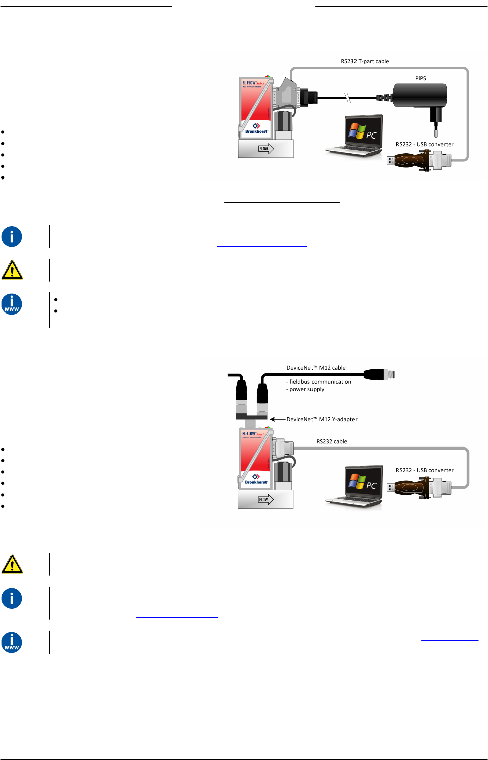
2.8.1 RS232 communication
Using a Windows computer, the instrument can
be monitored and operated via RS-232. For
operation, the free Bronkhorst FlowWare tools
can be used, providing a comprehensive user
interface to the digital instrument functions.
This example uses the following components:
EL-FLOW® Select
RS-232 T-part cable (art no. 7.03.366)
RS-232 to USB converter (art no. 9.09.122)
Windows computer (for readout and control)
Plug-in Power Supply (PiPS, art no. 7.03.422)
Connect the T-part cable with the 9-pin D-sub connector on the side of the instrument and use the RS-232/USB converter to
connect the other end of the cable with a free USB port of the computer.
For communication with a PLC or other controlling device, a 9-pin D-sub cable with a loose end (part no. 7.03.004,
7.03.536 or 7.03.537) can be used. Consult the RS-232 hook-up diagram for wiring details.
For RS-232 communication at baud rates up to 38400 Baud the maximum allowable cable length is 10 m. For higher
baud rates, use a maximum cable length of 3 m.
For more information about communication through the RS-232 interface, consult the RS-232 manual.
The FlowWare tools and associated documentation can be downloaded from the Accessories and software section on
the Bronkhorst® product pages (www.bronkhorst.com/products).
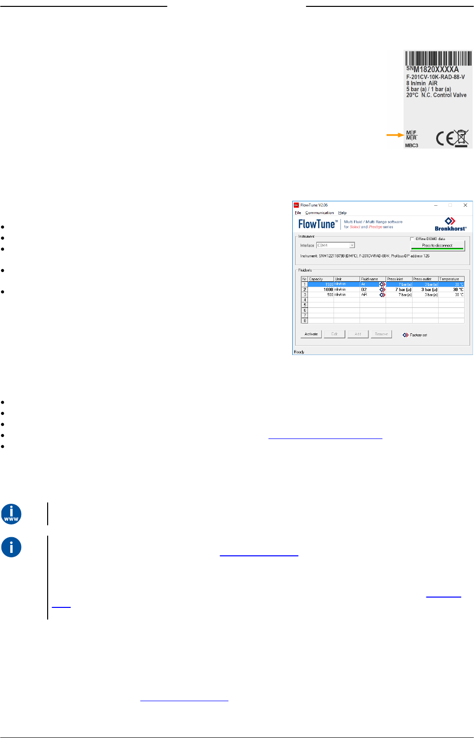
2.8.2 Fieldbus communication
The instrument can be connected to a fieldbus
system with the optional fieldbus connector on
top. At the same time, RS-232 communication
with a Windows computer is possible through
the 9-pin D-sub connector on the side of the
instrument.
This example uses the following components:
EL-FLOW® Select with DeviceNet™ interface
DeviceNet™ M12 cable (art no. 7.03.323)
DeviceNet™ M12 Y adapter (art no. 7.03.319)
RS-232 cable (art no. 7.03.367)
RS-232 to USB converter (art no. 9.09.122)
Windows computer (for readout and control)
Note that the used fieldbus components in this
example are specific to DeviceNet™. For connecting with other fieldbus systems, other cables and adapters are needed.
Always check the total power consumption of your instruments before connecting them to a fieldbus system. Do not exceed
the maximum power of the power supply unit.
For all available fieldbus types except PROFIBUS DP, the fieldbus connection on is used to power and operate the
instrument. For PROFIBUS DP, the instrument needs to be powered through the 9-pin D-sub connector on the side of the
instrument as shown in RS232 communication.
For information about setting up a fieldbus network with Bronkhorst® instruments, consult the according fieldbus manual.
If you need assistance with setting up a fieldbus system, contactyour Bronkhorst representative for information.

Bronkhorst®
Instruction Manual EL-FLOW® Select 9.17.099N18
2.8.3 E-8000 power supply, readout and control
Using an E-8000 module, instruments can be
powered (100…240 Vac) and operated via RS-
232. Most digital parameters and functions are
accessible via the display interface and the
control buttons.
This example uses the following components:
2x EL-FLOW® Select
2x RS-232/power supply cable (art no.
7.03.016/7.03.538/7.03.539)
E-8000 power supply, readout and control
module
Consult the E-8000 manual (document 9.17.076) for more information. This manual can be downloaded from the
Accessories and software section on the Bronkhorst® product pages (www.bronkhorst.com/products).
2.8.4 BRIGHT readout and control
Most digital parameters and functions are
accessible via the display interface and control
buttons of a BRIGHT readout and control
module (type B1 or B2). When a BRIGHT module
is installed, no other RS-232 connection can be
established with the instrument.
This example uses the following components:
EL-FLOW® Select
BRIGHT readout and control module
Plug-in Power Supply (PiPS, art no. 7.03.422)
Use the 9-pin D-sub connector on the side of the instrument to plug in the T-part that comes with the BRIGHT module.
Consult the BRIGHT manual (document 9.17.048) for more information. This manual can be downloaded from the
Accessories and software section on the Bronkhorst® product pages (www.bronkhorst.com/products).

Bronkhorst®
Instruction Manual EL-FLOW® Select9.17.099N 19
3 Operation
After correct installation of the EL-FLOW® Select and when all safety precautions have been taken into account, the
instrument can be used for measuring and/or controlling mass flow in the system.
3.1 Powering up and powering down
To maintain control of the fluid system and ensure a safe situation, it is recommended to turn on power before applying
fluid pressure and to switch off power only after the fluid system is depressurized.
When pressurizing, prevent pressure shocks by gradually bringing the fluid system to the required operating pressure.
For best performance, allow the device to warm up and stabilize for at least 30 minutes before starting measurement
and/or control. This may be done with or without media flow.
3.2 First use
In systems for use with corrosive or reactive media, purging for at least 30 minutes with a dry, inert gas (like Nitrogen or
Argon) is absolutely necessary before use. After use with corrosive, reactive or hazardous media (e.g. toxic or flammable),
purging is also necessary before the fluid system is exposed to air.
If the instrument is mounted in a position with upward or downward flow, adjusting the zero point is advised before using
the instrument for the first time. See Adjusting zero point for background information and instructions.
3.3 Mass flow measurement and control
When powering up, the instrument needs a couple of seconds
to start up the electronics. As soon as the start-up sequence
has finished (green LED glows continuously), the instrument is
ready to measure mass flows, however, optimal accuracy is
only reached after warming up (see Powering up and
powering down).
After powering up, the control valve closes (normally open) or
stays closed (normally closed). The valve stays closed until the
instrument receives a setpoint from the active setpoint source.
The internal PID controller then immediately opens the control
valve, until the measured flow rate matches the setpoint. It
maintains the resulting flow rate until another setpoint is
given.
EL-FLOW® Select instruments are most accurate at the specified inlet/outlet pressure, temperature and process gas
conditions. However, the instrument will function properly in a wide range of varying conditions. It is strongly advised to
use the FlowTune™ software available with the instrument to set the correct process conditions if the actual process
conditions differ from the conditions for which the instrument is set (see Changing fluid set).
Although EL-FLOW® Select instruments have excellent temperature stability, the best accuracy is achieved when
temperature gradients across the instruments are avoided. Make sure that the gas temperature matches the ambient
temperature as good as possible and mount the instruments on a rigid (heat conducting) surface.
EL-FLOW® Select instruments handle pressure shocks in the system well, but are not insensitive to pressure fluctuations.
For optimum control stability, provide a stable (pressure controlled) inlet pressure with sufficient buffer volume between
the pressure regulator and the instrument and avoid installing multiple instruments or control valves in close proximity to
another with small volume piping in between.
Bronkhorst®
Instruction Manual EL-FLOW® Select 9.17.099N20
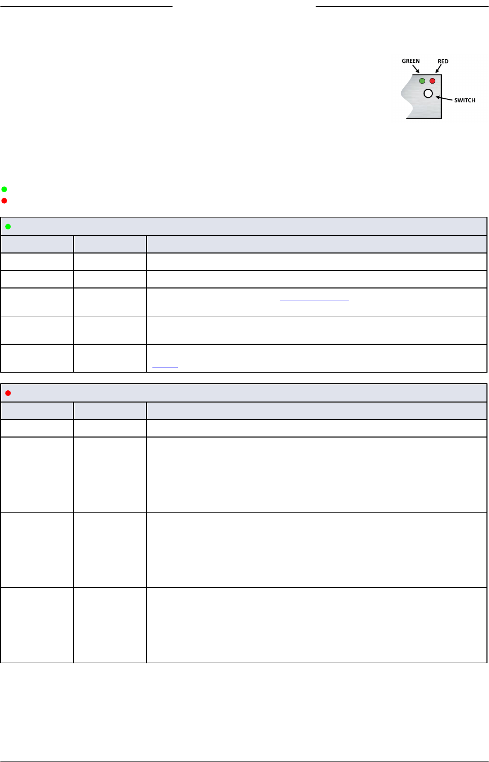
3.3.1 Changing fluid set
Optionally, EL-FLOW® Select instruments can provide Multi Fluid/Multi Range functionality (MFMR;
available if and as specified at ordering time). If MFMR is enabled, this is indicated in the lower left
corner of the serial number label.
MFMR enabled instruments are calibrated ex factory for a number of standard measuring ranges, which can be configured
for use with different fluids. Defining fluids and ranges and selecting the active fluid can be done via RS-232 with
FlowTune™.
FlowTune™ provides the following key functionality:
Definition and storage of up to eight different fluids in the instrument
Storing fluid properties for any gas
Changing upstream- and/or downstream pressure based on actual
process conditions
Re-ranging the full scale (FS) flow rate within the instrument's
supported flow range
Changing control speed per fluid set for faster or slower (smoother)
flow control
MFMR functionality is available for the full temperature and pressure range of the instrument. FlowTune™ checks the
changes for the following limitations:
Rangeability of the flow sensor for the selected fluid
Rangeability of the control valve for the selected fluid
Accuracy indication for the given flow range
Compatibility of selected gases with the used sealing materials (see Sealing material compatibility)
Limitations to the operating conditions
After all limitation checks are passed, the entered properties are stored in the instrument, including the required controller
settings. When switching to another fluid set, controller settings are automatically adjusted to the new process conditions,
so there is no need to change PID controller settings manually.
The FlowTune™ software and the associated documentation can be downloaded from the product pages on the Bronkhorst
website: www.bronkhorst.com/products
To connect with FlowTune™, use RS-232 communication via the 9-pin D-sub connector. In case a connection cannot be
established, use the power-up functionality of the multifunctional switch to switch to configuration mode and enable RS-
232 communication.
After configuring the required parameters, remember to return the instrument to the original communication mode.
It is advised to use FlowTune™ only in a non-operational environment. FlowTune™ will force the instrument to Valve Safe
State as soon as the connection is made. Be sure to close communication between FlowTune™ and the instrument
properly, to restore the normal operating mode.
3.4 Valve Safe State
When a controlling instrument is not powered or cannot communicate with the fieldbus network (if applicable), all electrical
valves operated by the instrument (whether integrated or external) automatically return to their default state. The default
state is closed for 'normally closed' valves (n/c) and fully open for 'normally open' valves (n/o).
Check the serial number label or the technical specifications to see which valve type is used on your instrument (if
applicable).
Bronkhorst®
Instruction Manual EL-FLOW® Select9.17.099N 21
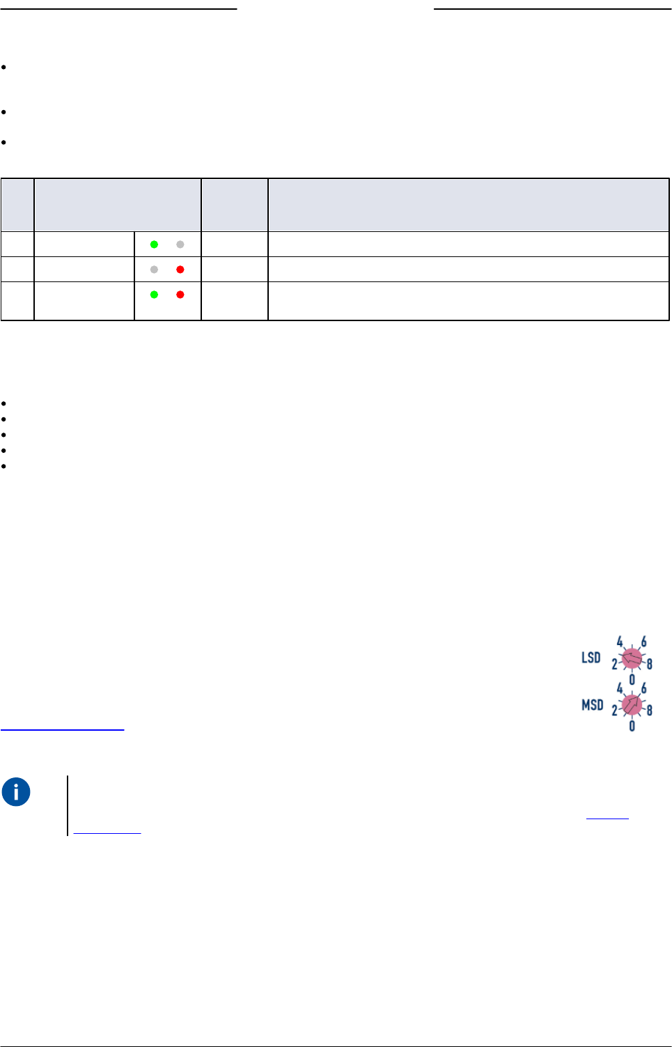
3.5 Manual controls
On top of the housing, the instrument is equipped with two LED indicators and a multifunctional
switch, which can be used to monitor the instrument visually and start several functions manually.
3.5.1 LED indications
The LEDs on top of the instrument indicate the operational state. The meaning of some indications depends on the specific
fieldbus interface of the instrument (if installed).
Mode/MOD
Operational mode
Error/NET
Error/warning indication
Green
Pattern
Time
Indication
off
continuous
Power off or program not running
on
continuous
Normal operation mode
short flash
0.1 sec on,
2 sec off
No communication, valves are in safe/default state
blink
0.2 sec on,
0.2 sec off
Instrument is busy performing a special function
long flash
2 sec on,
0.1 sec off
Configuration mode; the 9-pin D-sub connector is set for RS-232 communication
(ProPar) at 38400 Baud
Red
Pattern
Time
Indication
on
continuous
Critical error; the instrument needs servicing before it can be used
short flash
0.1 sec on,
2 sec off
FLOW-BUS
Node occupied: re-install instrument
PROFIBUS DP
No data exchange between master and slave (automatic recovery)
Modbus
Data is being received or transmitted
DeviceNet™
Minor communication error
EtherCAT®
Instrument is not in OP mode
PROFINET
No application relation established
blink
0.2 sec on,
0.2 sec off
FLOW-BUS
Waiting for communication
PROFIBUS DP
Not used
Modbus
Not used
DeviceNet™
No bus power
EtherCAT®
Not used
PROFINET
Not used
long flash
2 sec on,
0.1 sec off
FLOW-BUS
Not used
PROFIBUS DP
Requested parameter not available
Modbus
Not used
DeviceNet™
Serious communication error; manual intervention needed
EtherCAT®
Configuration error
PROFINET
Configuration error (e.g. a requested parameter is not available)

Bronkhorst®
Instruction Manual EL-FLOW® Select 9.17.099N22
Green and red (alternating)
Pattern
Time
Indication
slow wink
1 sec on,
1 sec off
Alarm indication; minimum/maximum alarm, power-up alarm, limit reached or batch
size reached
normal wink
0.2 sec on,
0.2 sec off
Wink mode; by sending a command to the Wink parameter, the instrument flashes its
LEDs, so that it can be located in the physical setup
fast wink
0.1 sec on,
0.1 sec off
Selected action started (after releasing the multifunctional switch)
DeviceNet™ instruments have different LED indications, that replace the standard indications described in this section (see
further).
3.5.1.1 Interface status
On instruments with an Ethernet based fieldbus interface, a third LED (bi-color; green and red) indicates the status of the
communication interface:
Pattern
Time
EtherCAT®
PROFINET
off
continuous
Power off or initializing
Interface not (yet) started
on, green
continuous
Normal operation
Normal operation, application relation
established with I/O controller
blinking,
green
0.2 sec on,
0.2 sec off
Pre-operational
Initializing
blinking, red
0.2 sec on,
0.2 sec off
Invalid state change
Link status OK, no application relation
with I/O controller
on, red
continuous
n/a
No link
single flash,
red
0.2 sec on,
1 sec off
Invalid configuration
n/a
double flash,
red
0.2 sec on,
0.2 sec off,
0.2 sec on,
1 sec off
Communication timeout (e.g.
communication cable disconnected)
n/a
Ethernet indicators
On instruments with an Ethernet based interface, the RJ-45 connection sockets have two integrated LED indicators, with
standard Ethernet functionality:
Amber: Ethernet speed
Green: Ethernet link/activity
3.5.1.2 DeviceNet™ indications
DeviceNet™ instruments have two bi-color LEDs (green/red) to indicate network and module status. The indications below
replace the standard LED indications:
/
MOD
Module status
/
NET
Network status

Bronkhorst®
Instruction Manual EL-FLOW® Select9.17.099N 23
Module status
Pattern
Time
Indication
off
continuous
No power
on, green
continuous
Normal operation mode
blinking,
green
0.5 sec on,
0.5 sec off
Device is in standby mode or configuration is missing, incomplete or incorrect
/ alternating
0.5 sec green,
0.5 sec red
Self test mode
on, red
continuous
Critical error; the instrument needs servicing before it can be used
Network status
Pattern
Time
Indication
off
continuous
Power off or offline
on, green
continuous
Online , connected, link OK
blinking,
green
0.5 sec on,
0.5 sec off
Online, not connected; the instrument is online but has no connections to other
nodes or is not allocated to a master
blinking, red
0.5 sec on,
0.5 sec off
Connection timed out
on, red
continuous
Critical link failure; the device cannot connect to the network
3.5.2 Multifunctional switch
Some special instrument functions can be started manually using the multifunctional switch near the indication LEDs. These
functions are available in analog as well as in digital operation mode.
3.5.2.1 Normal operating functions
In order to access these functions, press and hold the switch while the instrument is in normal operation mode (green
LED lit continuously).
As long as the switch is held, the LEDs show a repeating sequence of patterns, where each pattern indicates a function.
All patterns in this sequence are continuous.
Each pattern is shown for a number of seconds; in the table below, the column labeled Hold time indicates the time frame
during which a pattern is shown.
To start the required function, release the switch when the LEDs show the associated pattern.
(green)
(red)
Hold time
Function
off
off
0…1 sec
No action
off
off
1…4 sec
1. In case of a min/max alarm: reset alarm
2. FLOW-BUS: Auto-install to bus - lets instrument obtain free node address
Note: min/max alarm (if any) has to be reset before auto install can be performed.
off
on
4…8 sec
Reset instrument; clear all warnings and error messages and restart the instrument
on
off
8…12 sec
Auto-zero; re-adjust the zero-point of the instrument (flow meters/controllers only)
on
on
12…16 sec
Enable FLASH mode for firmware update:
the instrument shuts down and both LEDs are switched off
at the next power-up, the instrument will be active again
See Adjusting zero point for background information and instructions on how to adjust the zero point of an instrument.
Do not adjust the zero point before having taken notice of the instructions.

Bronkhorst®
Instruction Manual EL-FLOW® Select 9.17.099N24
3.5.2.2 Power-up functions
In order to access these functions, press and hold the switch while powering up the instrument.
As long as the switch is held, the LEDs show a repeating sequence of patterns, where each pattern indicates a function.
All patterns in this sequence are flashing (0.2 sec on, 0.2 sec off).
Each pattern is shown for a number of seconds; in the table below, the column labeled Hold time indicates the time frame
within the sequence during which a pattern is shown.
To start the required function, release the switch when the LEDs show the associated pattern.
(green)
(red)
Hold time
Function
off
off
0…4 sec
No action
off
on
4…8 sec
Restore factory settings (except communication settings)
on
off
8…12 sec
FLOW-BUS: auto install to bus; let the instrument obtain a free node address from
the FLOW-BUS system
Other protocols: no action
on
on
12…16 sec
Activate or deactivate configuration mode
The 9-pin D-sub connector is set to RS-232 communication (ProPar) at baud rate
38400
In configuration mode, the green LED blinks (2 seconds on, 0.1 second off)
Deactivate configuration mode by selecting this function again at the next power-
up
3.5.2.3 Control mode - readout/change
Reading control mode
By briefly pressing the switch 2 times within 1 second in normal operation mode, the instrument shows its current
control mode with a series of consecutive LED indication patterns.
The number of flashes corresponds to the current value of parameter Control Mode (see Special parameters).
Step
Pattern
Indication
1
Green
number of flashes indicates the tens of the parameter value
2
Red
number of flashes indicates the units of the parameter value
Examples:
for value 1 (control mode 'Analog input'), the green LED will flash 0 times and the red LED 1 time
for value 22 (control mode 'Valve Safe State'), the green and red LED will each flash 2 times
Changing control mode
By briefly pressing the switch 4 times with intervals of up to 1 second in normal operation mode, the instrument enters a
state in which the control mode can be changed.
This is done in 2 steps, each represented by a LED indication pattern (green or red; see table below).
The number of flashes corresponds to the available values of parameter Control Mode (see Special parameters).
At the start of each step, the according LEDs starts flashing fast (0.1 second on, 0.1 second off). By pressing and holding
the switch, the associated action is started and the flashing slows (0.5 seconds on, 0.5 seconds off).
Step
Pattern
Maximum
flash
count
Action
1
Green
2
set tens of parameter value
2
Red
9
set units of parameter value

Bronkhorst®
Instruction Manual EL-FLOW® Select9.17.099N 25
To execute a step, follow these instructions:
Press and hold the switch (flashing slows)
To select value 0 (zero), release the switch within 1 second, otherwise:
Count the number of LED flashes
Release the switch when the required value is reached
In case you lose count, keep the switch pressed and wait until the flash count reaches its maximum and restarts
On completion of step 1, the instrument automatically advances to step 2. When both steps have been completed, the
instrument returns to its normal operation mode.
If the switch is not pressed within 60 seconds after starting a step, all changes are canceled and the instrument returns to its
normal operation mode.
Note that this procedure also sets the default control mode of the instrument (contrary to changing the control mode
digitally).
3.5.2.4 Network settings - readout/change
Reading network settings
By briefly pressing the switch 3 times with intervals of up to 1 second in normal operation mode, the instrument shows
its current node address and baud rate with a series of consecutive LED indication patterns:
Step
Pattern
Indication
1
Green
number of flashes indicates the tens of the node address
2
Red
number of flashes indicates the units of the node address
3
Green and red
(simultaneous)
number of flashes indicates the baud rate
Examples:
for node address 35, the green LED will flash 3 times and the red LED 5 times
for node address 116, the green LED will flash 11 times and the red LED 6 times
On DeviceNet™ the node address is called MAC ID.
The number of flashes for the baud rate indication is associated with the following baud rates:
Number of
flashes
(index)
Baud rate
FLOW-BUS
Modbus
(ASCII/RTU)
PROFIBUS DP
CANopen
DeviceNet™
Ethernet based
0
automatically
detected
1
187500
9600
9600
1000000
125000
100000000
2
400000
19200
19200
800000
250000
3
38400
45450
500000
500000
4
56000
93750
250000
5
57600
187500
125000
6
115200
500000
50000
7
128000
1500000
20000
8
256000
3000000
10000
9
6000000
10
12000000
Bronkhorst®
Instruction Manual EL-FLOW® Select 9.17.099N26
Changing network settings
By briefly pressing the switch 5 times with intervals of up to 1 second in normal operation mode, the instrument enters a
state in which the node address and baud rate can be changed (non-Ethernet based protocols only; for Ethernet based
protocols, network parameters are configured by the fieldbus master and cannot be set on the instrument).
Changing network parameters with the multifunctional switch is done in 3 steps, each represented by a LED indication
pattern (see table below).
At the start of each step, the according LED(s) start(s) flashing fast (0.1 second on, 0.1 second off). By pressing and holding
the switch, the associated action is started and the flashing slows (0.5 seconds on, 0.5 seconds off).
Step
Pattern
Maximum
flash
count
Action
1
Green
12
set tens of node address
2
Red
9
set units of node address
3
Green and red
(simultaneous)
10*
set baud rate index (number of flashes)
*) maximum count depends on the supported baud rates of the fieldbus. See the baud rate table above for supported baud
rates and associated indexes.
To execute a step, follow these instructions:
Press and hold the switch (flashing slows)
To select value 0 (zero), release the switch within 1 second, otherwise:
Count the number of LED flashes
Release the switch as soon as the required value is reached
In case you lose count, keep the switch pressed and wait until the flash count reaches its maximum and restarts
On completion of a step, the instrument automatically advances to the next step. When all required steps have been
completed, the instrument returns to its normal operation mode.
If the switch is not pressed within 60 seconds after starting a step, all changes in the previous steps are cancelled and the
instrument returns to its normal operation mode.
3.5.3 Rotary switches
If the instrument is equipped with a fieldbus interface, it also has 2 or 3 rotary switches (depending on the specific interface
type).
Using the MSD and LSD switches, the required node address of the instrument can be selected, in the
range from 1 to 99. MSD (Most Significant Digit) sets the tens, LSD (Least Significant Digit) sets the units;
in the image to the right the address is set to 63 (note that the actual appearance and orientation of the
switches can differ from the image).
If both switches are set to 0, the node address is set by the according digital parameter (see section
Network configuration).
The switches can be adjusted using a small flat blade screwdriver.
On FLOW-BUS and Modbus instruments, the rotary switches only set the node address for communication through the
fieldbus connector (if present). If the instrument is configured for RS-485 communication through the 9-pin D-sub
connector (FLOW-BUS or Modbus), use the according digital parameter to set the node address (see section Network
configuration).

Bronkhorst®
Instruction Manual EL-FLOW® Select9.17.099N 27
DeviceNet™
On DeviceNet™ instruments, the MSD switch provides a smaller range (0-6) and a 'P' option. With this option, the node
address is set according to the digital parameters (instead of by setting both switches to 0).
DeviceNet™ instruments have a third switch, for setting the baud rate:
Data rate
Baud rate
1
125000 (default)
2
250000
5
500000
P
Programmable
With the 'P' option, the baud rate is set by the according digital parameter
EtherCAT®
Bronkhorst® instruments with an EtherCAT® interface have 3 rotary switches, with which the EtherCAT® Second Address can be
set in the range of 0 – 4095 (0xFFF). This value is copied to the Configured Station Alias register (address 0x0012:0x0013) at
instrument start-up.
3.6 Communication
The following table lists the supported communication modes of the EL-FLOW® Select:
Connection
Type
Communication standard
Fieldbus/protocol
9-pin D-sub
Analog
0…5Vdc
0…10Vdc
0…20mA
4…20mA
n/a
Digital
RS232
ProPar
RS485
FLOW-BUS
Modbus ASCII/RTU
Fieldbus specific
Digital
RS485
FLOW-BUS
Modbus ASCII/RTU
PROFIBUS DP
Can
CANopen
DeviceNet™
Ethernet
EtherCAT®
Ethernet/IP
Modbus TCP/IP
POWERLINK
PROFINET
The communication standards (analog and digital) and fieldbus interface (if applicable) are specified at ordering time, i.e.:
In analog mode, the instrument is set to the specified voltage/current range
The dedicated fieldbus connection only provides the specified fieldbus interface
Simultaneous analog and digital operation
The instrument can be monitored and operated through the analog and a digital interface simultaneously, but it only
accepts a setpoint from one of both (this is called the control mode; see Special parameters for more information).
In analog mode, the analog input and output signals are translated to the digital setpoint and measure parameter
respectively.
Bronkhorst®
Instruction Manual EL-FLOW® Select 9.17.099N28
3.6.1 Analog operation
With analog operation the following signals are available:
output signal: measured value
input signal: setpoint (controller only)
Setpoints below 2% of the full scale will be interpreted as 0%.
The analog interface type that is installed on the 9-pin D-sub connector can be found in the model key of the instrument.
3.6.2 Digital operation (RS232)
Digital operation (RS-232 or fieldbus) adds extra features to the instrument, such as:
Direct reading with a readout/control module or host computer
Diagnostics
Multi-range functionality
Device identification
Adjustable minimum and maximum alarm limits (see Alarms)
(Batch) counter
Make sure that the instrument’s baud rate matches the baud rate of the master/application, otherwise no communication
can be established. See section Network configuration for changing baud rate, node address and parity setup.
For RS232 communication, the maximum cable length is 10 m for baud rates up to 38400 Baud. For higher baud rates,
use cable lengths of maximum 3 m.
If the 9-pin D-sub connector is set for RS-485 communication, the instrument will not respond to an RS-232 master. In
that case, use the multifunctional switch to enter configuration mode and enable RS-232 communication.
After configuring the required parameters, follow the same procedure to leave configuration mode and restore the
original communication settings (otherwise, configuration mode will remain enabled after the next power-up).
For more information about communication through the RS232 interface, consult the RS232 manual (document no.
9.17.027).
3.6.2.1 FlowDDE
Digital Bronkhorst® instruments can be operated via RS-232 using the Bronkhorst® FlowDDE server application. Dynamic
Data Exchange (DDE) provides a basic level of inter process communication between Windows applications. Together with a
client application, either self-made or with a third party SCADA program, it is possible to create an easy way of data
exchange between the flow meter/controller and a Windows application. For instance, a cell in a Microsoft Excel
spreadsheet can be linked to the measured value of an instrument; FlowDDE updates the cell automatically when the
measured value changes.
FlowDDE uses specific parameter numbers for communicating with the instrument. A DDE parameter number is a unique
number in a special FlowDDE instruments/parameter database and not the same as the parameter number from the process
on an instrument. FlowDDE translates the node-address and process number to a channel number.
DDE-client applications communicate with the FlowDDE server by using DDE messages. Before messages can be exchanged,
a DDE link has to be made. A DDE link consists of three parts: the server, the topic and an item. For separation the characters
'|' and '!' may be used, so a DDE link in e.g. Microsoft Excel becomes: Server|Topic!Item.
For standard instrument parameters and the FlowDDE server, these are:
Server: FlowDDE or FlowDDE2
Topic: ‘C(X)’ for channel number X
Item: ‘P(Y)’ for parameter number Y
An example of a DDE link in a Microsoft Excel cell is =FlowDDE|’C(1)’!’P(8)’ to read parameter 8 of channel 1.

Bronkhorst®
Instruction Manual EL-FLOW® Select9.17.099N 29
When not using FlowDDE for communication with the
instrument, parameters are addressed by:
Node address
Process number
Parameter number
See section Digital parameters for more information about
instrument parameters.
For more information about FlowDDE, including setting up a DDE link, consult the FlowDDE Manual (document no.
9.17.067) or the help file in the application.
3.6.2.2 Software (DDE applications)
Examples of free Bronkhorst® DDE client applications: FlowPlot and FlowView. Other software programs supporting DDE are
for example MS-Office, LabVIEW, InTouch and Wizcon.
Bronkhorst® software applications 'FlowView' (left) and 'FlowPlot' (right)
FlowDDE and other Bronkhorst® applications are available on the support CD or can be downloaded from the product
pages on the Bronkhorst website: www.bronkhorst.com/products
3.6.3 Digital fieldbus operation (RS485)
The following optional fieldbuses are available for EL-FLOW® Select instruments. For all mentioned fieldbus systems, except
FLOW-BUS, instruments act as slaves on the master/slave bus system. There is no mutual communication between slaves,
only between master and slave.

Bronkhorst®
Instruction Manual EL-FLOW® Select 9.17.099N30
FLOW-BUS
Digital Bronkhorst® instruments can be monitored and operated using the free FlowWare software tools for Windows.
These tools provide a graphical interface to the ProPar protocol (used by FLOW-BUS), for monitoring and editing parameter
values.
The FlowWare toolkit provides functionality for monitoring and operating digital instruments (Bronkhorst FlowSuite,
FlowPlot) and selection of the active fluid and configuration of the fieldbus connection (if applicable). For instruments that
support the definition and use of multiple fluids, FlowTune™ can be used to define and store fluids in the instrument and
select the active fluid.
Digital instrument parameters are made accessible by FlowDDE, a Dynamic Data Exchange server (DDE) that handles
communication between the instrument and (dedicated) client software in Windows (e.g. FlowPlot). FlowDDE can also be
used by other client applications, such as Microsoft Office or custom made software, built with third party development
software like LabVIEW or a SCADA platform.
The FlowWare tools and associated documentation can be downloaded from the product pages on the Bronkhorst website:
www.bronkhorst.com/products
FlowWare can only be used if the 9-pin D-sub (power) connector is configured for RS232 communication. If necessary , use
the power-up functionality of the multifunctional switch to switch to configuration mode and enable RS232
communication.
After configuring the required parameters, remember to leave configuration mode and restore the original
communication settings (otherwise, configuration mode remains enabled after power down).
Modbus
In a Modbus system instruments can be monitored and operated using third party software as a master device, such as
LabVIEW, ModScan, or a Modbus PLC.
PROFIBUS-DP
Instruments in a PROFIBUS DP system can be monitored and operated using third party software as a master device, such as
TIA Portal (by Siemens).
To operate a PROFIBUS DP device, a so-called GSD file (General Station Description) has to be loaded into the software. The
GSD file contains all necessary configuration information to operate the device in a PROFIBUS DP system, including all
available operating parameters with their data types.
A GSD file for Bronkhorst® instruments can be downloaded from the product pages on the Bronkhorst website:
www.bronkhorst.com/products
DeviceNet™
Instruments in a DeviceNet™ system can be monitored and operated using third party software as a master device, such as
TIA Portal (by Siemens).
To configure a device, a so-called EDS file (Electronics Data Sheet) can be loaded into the software. The EDS file contains all
necessary configuration information to operate the device in a DeviceNet™ system, including communication and network
configuration, and all available operating parameters with their data types.
An EDS file for Bronkhorst® instruments can be downloaded from the product pages on the Bronkhorst website:
www.bronkhorst.com/products
EtherCAT®
Instruments in an EtherCAT® system can be monitored and operated using third party software as a master device, such as
SyCon® (by Hilscher GmbH).
To configure a device, a so-called ESI file (EtherCAT® Slave Information) can be loaded into the software. The ESI file contains
all necessary configuration information to operate the device in a EtherCAT® system, including communication and network
configuration, and all available operating parameters with their data types.
An ESI file for Bronkhorst® instruments can be downloaded from the product pages on the Bronkhorst website:
www.bronkhorst.com/products

Bronkhorst®
Instruction Manual EL-FLOW® Select9.17.099N 31
PROFINET
Instruments in a PROFINET system can be monitored and operated using third party software as a master device, such as TIA
Portal (by Siemens).
To configure a device, a so-called GSDML file (General Station Description Markup Language) can be loaded into the
software. The GSDML file contains all necessary information, in XML format, to operate the device in a PROFINET system,
including communication and network configuration, and all available operating parameters with their data types.
A GSDML file for Bronkhorst® instruments can be downloaded from the product pages on the Bronkhorst website:
www.bronkhorst.com/products
3.7 Adjusting zero point
Zero-stability
The zero point of a Bronkhorst® flow meter/controller (the measurement signal that indicates the absence of a flow) is
factory adjusted at approximately 20 °C and atmospheric pressure (ambient conditions), with the instrument positioned
upright. Under normal circumstances (i.e. at stable process conditions), the zero point will remain stable. However, over time
several factors can induce a slight deviation of the measured value from the zero point, causing the instrument to detect a
flow when in reality there is none. Readjusting the zero point eliminates this deviation.
After installation or relocation, always check the zero point.
If the instrument still detects a (steady) flow while all valves are closed and the fluid system is leak tight, adjusting the
zero point is recommended.
Prerequisites
Zeroing an instrument requires that:
the ambient conditions (temperature, pressure) match those of the operating environment of the instrument.
the instrument is filled homogeneously and pressurized with the operational media, according to the typical process
conditions.
the instrument has been warmed up sufficiently.
there is absolutely no flow through the instrument; preferably, this is achieved by closing a valve immediately after the
outlet of the instrument (control valve, shut-off valve).
Blocking the flow through the instrument is essential; zeroing an instrument while there is still a flow will lead to
measurement errors.
Procedure
The zero point may be re-adjusted digitally (via RS-232 or fieldbus) or manually, using the multifunctional switch. Regardless
of the preferred method, once started, the zeroing procedure itself takes approximately 10 seconds to complete (longer if
the output signal is unstable)
3.7.1 Using multifunctional switch
To start the autozero function with the multifunctional switch, follow these instructions:
1. Change the setpoint of the instrument to 0 (zero).
2. Press and hold the multifunctional switch. After 4 seconds, the red LED lights up; another 4 seconds later the red LED
extinguishes and the green LED lights up.
3. At that moment (which is after 8 to 12 seconds), release the switch.
The green LED starts to blink fast, indicating that the autozero procedure is in progress. After (successful) completion, the
green LED lights up continuously, while the output signal is 0 % (parameter Measure = 0).

Bronkhorst®
Instruction Manual EL-FLOW® Select 9.17.099N32
3.7.2 Via digital communication
Bronkhorst FlowSuite and FlowPlot provide an easy way to adjust the zero point of an instrument using RS-232
communication; the Autozero function automatically performs the procedure described here.
To adjust the zero point using digital communication, set parameter values in the following sequence (see section Digital
parameters for more information about instrument parameters):
Sequence #
Parameter
Value
Action
1
Setpoint or fSetpoint
0
stop flow
2
Init Reset
64
unlock secured parameters
3
Control Mode
9
enable calibration mode
4
Calibration Mode
0
reset calibration mode
5
Calibration Mode
9
start zeroing
The green LED starts to blink fast, indicating that the zeroing procedure is in progress. On completion, the green LED lights
up, while the output signal is 0 % (parameter Measure = 0). At the same time, parameter Control Mode returns to its initial
value. If the procedure is successful, parameter Calibration Mode changes to 0 (idle). If the procedure fails, Calibration Mode
changes to 255.
After performing the procedure, remember to set parameter Init Reset to value 82 to lock secured parameters.

Bronkhorst®
Instruction Manual EL-FLOW® Select9.17.099N 33
4 Digital parameters
This section describes the most commonly used parameters for digital operation of the EL-FLOW® Select. Descriptions are
grouped by category in tables as shown below:
Type
Access
Range
FlowDDE
FLOW-BUS
Modbus
[type]
RW
[x]…[y]
[DDE par]
[Pro]/[Par]
[address]/[register]
In this manual, parameter names are printed in italics (reverted to normal where embedded in italics, like in this tip).
Type
Unsigned char 1 byte unsigned integer (0…255)
Unsigned int 2 byte unsigned integer, MSB first (0…65535)
Unsigned long 4 byte unsigned integer, MSB first (0…4294967295)
Float 4 byte floating point, IEEE 32-bit single precision, MSB first
Unsigned char [x] x byte text string
Access
R Parameter value can be read
W Parameter value can be written
Parameter is secured and only accepts values if parameter Init Reset is set to 'unlocked' first
Range
Some parameters only accept values within a certain range:
[x] Minimum value
[y] Maximum value
FlowDDE
Parameter number within FlowDDE
FLOW-BUS
FLOW-BUS uses the ProPar protocol, where parameters are identified by a unique combination of a process number and a
parameter number.
For more information about setting up a FLOW-BUS network with Bronkhorst® instruments, consult the FLOW-BUS
manual (see Documentation).
For more information about the ProPar protocol, consult the RS-232 manual (see Documentation).
Modbus
In the Modbus protocol, parameters are accessed by specifying their unique decimal register number or corresponding PDU
address (Protocol Data Unit). The PDU address is the hexadecimal translation of the register number minus 1, e.g. register
number 1 corresponds to PDU address 0x0000, register number 11 corresponds to PDU address 0x000A:
[address] Hexadecimal PDU address
[register] Decimal register number
Modbus address blocks are two bytes big. Larger data types use up to 8 subsequent address blocks, resulting in a
maximum variable length of 16 bytes. Values longer than the maximum length are truncated.
For more detailed information about setting up a Modbus network with Bronkhorst® instruments, consult the Modbus
manual (see Documentation).
Other interface protocols
Parameter descriptions in this document are based on their availability with FLOW-BUS, Modbus or RS-232 (ProPar)
communication. Due to limitations in, for example, memory capacity or communication properties, definition files for other
fieldbus systems usually do not make all parameters available.
Not all parameters described in this document are necessarily available with all digital interface types. For information
about parameter access and availability for Bronkhorst® instruments in a specific fieldbus network, consult the according
fieldbus manual.

Bronkhorst®
Instruction Manual EL-FLOW® Select 9.17.099N34
4.1 Special parameters
Init Reset
Type
Access
Range
FlowDDE
FLOW-BUS
Modbus
Unsigned char
RW
82/64
7
0/10
0x000A/11
Init Reset is used to unlock secured parameters (marked with a symbol) for writing. It supports the following values:
Value
Description
64
unlocked, secured parameters can be read and written to
82
locked, secured parameters are read-only
At power-up, Init Reset is always set to ‘Locked’ (value 82).
Reset
Type
Access
Range
FlowDDE
FLOW-BUS
Modbus
Unsigned char
R
0…7
114
115/8
0x0E68/3689
This parameter is used to reset the program, counter or alarms.
Value
Description
0
No reset
1
Reset counter
2
Reset alarm
3
Reset counter
4
Reset and disable counter
5
Reset firmware program (soft reset)
6
Reset Alarm info error bit
7
Reset Alarm info warning bit
The Reset parameter may be disabled by Reset Alarm Enable or Reset Counter Enable. Make sure the value is accepted
by sending value 0 first.
Wink
Type
Access
Range
FlowDDE
FLOW-BUS
Modbus
Unsigned char [27]
W
0…9*
1
0/0
0x0000/1
Sending any text string value between 1 and 9 to this parameter makes the indication LEDs (if present) blink for a couple of
seconds. This can be useful in order to identify a specific device in a large fieldbus network.
*) Modbus only supports value 14592
Control Mode
Type
Access
Range
FlowDDE
FLOW-BUS
Modbus
Unsigned char
RW
0…255
12
115/1
0x0024/37
Control Mode is used to select different control modes of the instrument and determines from which source(s) it accepts a
setpoint.
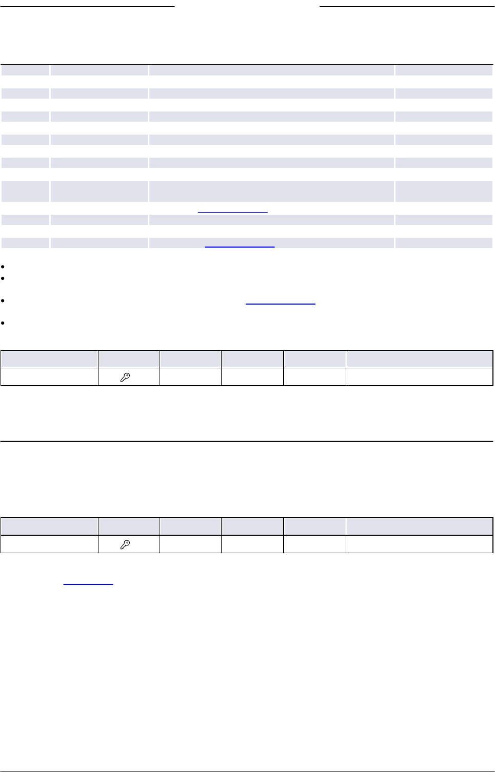
Bronkhorst®
Instruction Manual EL-FLOW® Select9.17.099N 35
The following modes are available:
Value
List option
Description
Setpoint source
0
Bus/RS232
Normal digital operation
Fieldbus or RS-232
1
Analog input
Normal analog operation
Analog input
2
FLOW-BUS slave
Acting as slave instrument on FLOW-BUS
FLOW-BUS master
3
Valve close
Controller disabled, valve closed
4
Controller idle
Controller disabled, valve frozen in current position
7
Setpoint 100%
Setpoint fixed at 100 %
8
Valve fully open
Controller disabled, valve fully open
9
Calibration mode
Calibration mode enabled
10
Analog slave
Acting as slave of other instrument in analog mode
Analog input
12
Setpoint 0%
Setpoint fixed at 0%
13
FLOW-BUS analog slave
Acting as slave of other instrument on FLOW-BUS, slave
factor set by analog input signal
Analog input
18
RS232
Controlling, default/safe state disabled
Fieldbus or RS-232
20
Valve steering
Controller disabled, setpoint redirected to Valve Output
21
Analog valve steering
Controller disabled, analog input redirected to Valve Output
22
Valve safe state
Instrument in default/safe state
Default value: 0 or 1 (as ordered).
If Control Mode is changed to value 0, 1, 9 or 18, the instrument returns to the default value at the next power-up or reset.
Other values are persistent.
Control Mode 18 prevents the instrument from assuming its default/safe state in the event of a digital communication
failure.
The column labeled List option shows the control modes as used in Bronkhorst® software.
Calibration Mode
Type
Access
Range
FlowDDE
FLOW-BUS
Modbus
Unsigned char
RW
0, 9, 255
58
1/4
0x0E61/3682
After enabling calibration mode by means of parameter Control Mode, this parameter is used to start the autozero function
of the flow sensor. The following modes are supported:
Value
Description
0
Idle (no action)
9
Start zeroing
255
Error (result of previous calibration mode)
4.1.1 Default control mode
IO Status
Type
Access
Range
FlowDDE
FLOW-BUS
Modbus
Unsigned char
RW
0…255
86
114/11
0x0E4B/3660
The instrument is set to accept a setpoint from either an analog or a digital source. Although this setting can be changed
with parameter Control Mode, the instrument usually returns to its default control mode at every power-up or reset. The
default control mode can be set with parameter IO Status; to change it, use the procedures as described below.
Changing from digital operation to analog operation:
1. Set parameter Init Reset to 64 (unlocked)
2. Read parameter IO Status
3. Add 64 to the read value
4. Write the new value to parameter IO Status
5. Set parameter Init Reset to 82 (locked)
Changing from analog operation to digital operation:
1. Set parameter Init Reset to 64 (unlocked)
2. Read parameter IO Status
3. Subtract 64 from the read value
4. Write the new value to parameter IO Status
5. Set parameter Init Reset to 82 (locked)

Bronkhorst®
Instruction Manual EL-FLOW® Select 9.17.099N36
The procedures described above do not change the value of parameter Control Mode. To apply the new default control
mode, reset or restart the instrument.
4.2 Measurement and control
Measure
Type
Access
Range
FlowDDE
FLOW-BUS
Modbus
Unsigned int
R
0…41942
8
1/0
0x0020/33
This parameter returns a dimensionless representation of the measured flow rate or pressure. Value 32000 corresponds to
100 %, the maximum value corresponds to 131.07 %.
Setpoint
Type
Access
Range
FlowDDE
FLOW-BUS
Modbus
Unsigned int
RW
0…32000
9
1/1
0x0021/34
The value of this parameter is a dimensionless representation of the required flow rate or pressure. Value 32000
corresponds to 100 %.
To convert Measure and Setpoint to actual mass or volume flows (fMeasure and fSetpoint respectively), use parameters
Capacity 100% and Capacity Unit (see Fluid set)
Temperature
Type
Access
Range
FlowDDE
FLOW-BUS
Modbus
Float
R
-250…500
142
33/7
0xA138…0xA139/41273…41274
This parameter returns the internal temperature in the instrument housing in °C, which is an approximation of the actual
media temperature.
Pressure
Type
Access
Range
FlowDDE
FLOW-BUS
Modbus
Float
RW
0…3.4E+38
143
33/8
0xA140…0xA141/41281…41282
In case an external pressure sensor is connected, this parameter returns the actual system pressure in bar(a).
If there is no external pressure sensor, the default value of this parameter is equal to parameter Inlet pressure.
4.2.1 Advanced measurement and control
fMeasure
Type
Access
Range
FlowDDE
FLOW-BUS
Modbus
Float
R
-3.4E+38…
3.4E+38
205
33/0
0xA100…0xA101/ 41217…41218
This parameter represents the value of parameter Measure, expressed in the selected Capacity Unit. Its value is calculated from
the dimensionless value of Measure, using the fluid set parameters Capacity 100% and Capacity Unit.
Fsetpoint
Type
Access
Range
FlowDDE
FLOW-BUS
Modbus
Float
RW
0…3.4E+38
206
33/3
0xA118…0xA119/ 41241…41242
This parameter represents the value of parameter Setpoint, expressed in the selected Capacity Unit. Conversion between
Fsetpoint and the dimensionless value of Setpoint uses fluid set parameters Capacity 100% and Capacity Unit.

Bronkhorst®
Instruction Manual EL-FLOW® Select9.17.099N 37
Setpoint Slope
Type
Access
Range
FlowDDE
FLOW-BUS
Modbus
Unsigned int
RW
0…30000
10
1/2
0x0022/35
The value of this parameter represents the time it would take to adjust the setpoint if it were changed from 0 to 100 %. This
feature can be used to smooth 'nervous' controller behavior, e.g. to reduce setpoint overshoot or undershoot.
The supported range corresponds to 0…3000 seconds. Default value = 0.
Example:
If Setpoint Slope = 100 it will take 10 seconds to adjust the setpoint if it is changed from 0 to 100%. A setpoint change of 20%
will take (20%/100%)*10 seconds = 2 seconds.
Analog Input
Type
Access
Range
FlowDDE
FLOW-BUS
Modbus
Unsigned int
R
0…65535
11
1/3
0x0023/36
This parameter contains a digital translation of the analog input signal (if applicable).
Valve Output
Type
Access
Range
FlowDDE
FLOW-BUS
Modbus
Unsigned long
RW
0…
16777215
55
114/1
0xF208…0xF209/61961…61962
This parameter represents the controller output signal for control valve operation.
4.3 Device identification
User Tag
Type
Access
Range
FlowDDE
FLOW-BUS
Modbus
Unsigned char[16]
RW
-
115
113/6
0xF130…0xF137/ 61745…61752
With this parameter, the instrument can be given a custom tag name, with a maximum of 16 characters.
Customer Model
Type
Access
Range
FlowDDE
FLOW-BUS
Modbus
Unsigned char[16]
RW
-
93
113/4
0xF120…0xF127/ 61729…61736
This parameter is used to add extra information to the model number information, such as a customer-specific model
number.
Serial Number
Type
Access
Range
FlowDDE
FLOW-BUS
Modbus
Unsigned char[20]
R
-
92
113/3
0xF118…0xF11F/ 61721…61728
Instrument serial number for identification.
BHT Model Number
Type
Access
Range
FlowDDE
FLOW-BUS
Modbus
Unsigned char[35]
RW
-
91
113/2
0xF110…0xF117/ 61713…61720
This parameter shows the Bronkhorst® instrument model type information.

Bronkhorst®
Instruction Manual EL-FLOW® Select 9.17.099N38
Firmware Version
Type
Access
Range
FlowDDE
FLOW-BUS
Modbus
Unsigned char[6]
R
-
105
113/5
0xF128…0xF12A/ 61737…61739
Revision number of the firmware
Identification Number
Type
Access
Range
FlowDDE
FLOW-BUS
Modbus
Unsigned char
RW
0…255
175
113/12
0x0E2C/3629
Bronkhorst® (digital) device type identification number.
Device Type
Type
Access
Range
FlowDDE
FLOW-BUS
Modbus
Unsigned char[6]
R
-
90
113/1
0xF108…0xF10A/ 61705…61707
Device type information string; this parameter contains an abbreviation referring to the identification number.
4.4 Alarms
Alarm settings are most easily accessible using Bronkhorst FlowSuite, FlowPlot or FlowView or a Bronkhorst® readout and
control unit.
The built-in alarm functionality can be used to handle different alarm types:
system errors and warnings
min/max alarms
response alarms
batch alarms
master/slave alarms
The alarm type can be set with parameter Alarm Mode. When an alarm is activated, the type can be read out using parameter
Alarm Info. An automatic setpoint change can be set using the parameters Alarm Setpoint Mode and Alarm New Setpoint. It is
also possible to set an alarm delay, to prevent overreaction to small disturbances, using parameter Alarm Delay Time. The
methods by which an alarm can be reset are controlled by Reset Alarm Enable.
Alarm Mode
Type
Access
Range
FlowDDE
FLOW-BUS
Modbus
Unsigned char
RW
0…3
118
97/3
0x0C23/3108
Available modes:
Value
Description
0
Alarm off
1
Alarm on absolute limits
2
Alarm on limits related to setpoint (response alarm)
3
Alarm at power-up(e.g. after power-down)
(On DeviceNet™ instruments, only modes 0 and 1 are available)

Bronkhorst®
Instruction Manual EL-FLOW® Select9.17.099N 39
Alarm Info
Type
Access
Range
FlowDDE
FLOW-BUS
Modbus
Unsigned char
R
0…255
28
1/20
0x0034/53
This parameter provides information about the event type(s) that triggered an alarm situation. The value is a bitwise
summation of the issued alarm types; convert the value to binary to see which types are issued. The following alarm types
can be issued:
Bit
Value
Type
Description
0
1
Error
Error flag raised
1
2
Warning
Warning flag raised
2
4
Minimum alarm
Measure < Alarm minimum limit
3
8
Maximum alarm
Measure > Alarm maximum limit
4
16
Batch counter alarm
Batch counter reached its limit
5
32
This bit only: Power-up alarm
Alarm possibly caused by a power dip
If combined with bit 2 or 3:
Response alarm
Difference between Measure and Setpoint too big
6
64
Master/slave alarm
Setpoint out of limits (caused by Slave factor)
7
128
Hardware alarm
Hardware error
Alarm Delay Time
Type
Access
Range
FlowDDE
FLOW-BUS
Modbus
Unsigned char
RW
0…255
182
97/7
0x0C27/3112
This value represents the time in seconds the alarm action will be delayed when an alarm limit has been exceeded. This
value also delays the alarm off action if an alarm limit is no longer exceeded.
Default value = 0.
Alarm Maximum Limit
Type
Access
Range
FlowDDE
FLOW-BUS
Modbus
Unsigned int
RW
0…32000
116
97/1
0x0C21/3106
Maximum limit for Measure to activate the maximum alarm situation (after Alarm Delay Time). Range 0…32000 represents 0…
100% signal. Alarm Maximum Limit must be greater than Alarm Minimum Limit.
Default value: 0.
Alarm Minimum Limit
Type
Access
Range
FlowDDE
FLOW-BUS
Modbus
Unsigned int
RW
0…32000
117
97/2
0x0C22/3107
Minimum limit for Measure to activate the minimum alarm situation (after Alarm Delay Time). Range 0…32000 represents 0…
100% signal. Alarm Minimum Limit must be smaller than Alarm Maximum Limit.
Default value: 0.
Alarm Setpoint Mode
Type
Access
Range
FlowDDE
FLOW-BUS
Modbus
Unsigned char
RW
0…1
120
97/5
0x0C25/3110
Specifies whether or not to change the setpoint after an alarm situation is activated.
Value
Description
0
No setpoint change (default)
1
Change setpoint to Alarm new setpoint
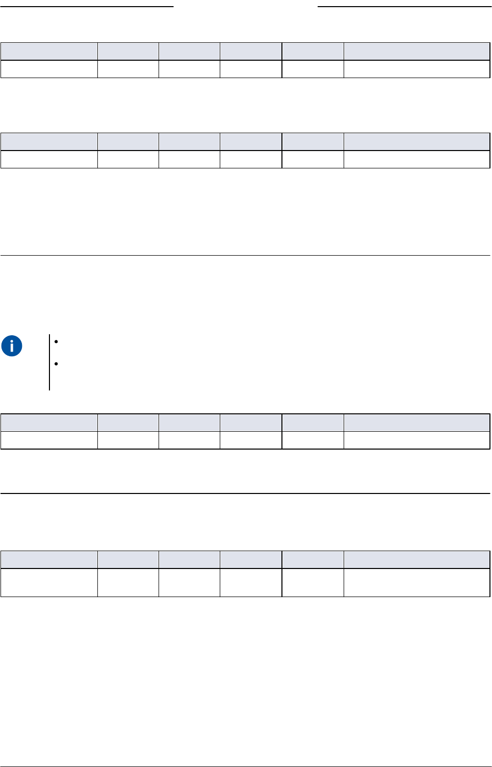
Bronkhorst®
Instruction Manual EL-FLOW® Select 9.17.099N40
Alarm New Setpoint
Type
Access
Range
FlowDDE
FLOW-BUS
Modbus
Unsigned int
RW
0…32000
121
97/6
0x0C26/3111
New (safe) setpoint during an alarm until reset. Range 0…32000 represents 0…100% setpoint.
Default value: 0
Reset Alarm Enable
Type
Access
Range
FlowDDE
FLOW-BUS
Modbus
Unsigned char
RW
0…15
156
97/9
0x0C29/3114
Available reset methods. The value is a bitwise summation of the enabled methods; convert the value to binary to see
which methods are enabled.
Default value: 15 (all bits/methods enabled)
The following methods are supported:
Bit
Value
Description
0
1
By hardware switch (if present)
1
2
Externally (obsolete)
2
4
By parameter Reset
3
8
Automatically (when alarm conditions no longer apply)
4.5 Counter
Counter settings are most easily accessible using Bronkhorst FlowSuite, FlowPlot or FlowView or a Bronkhorst® readout
and control unit.
When the instrument is powered down, it remembers the state of the counter. If the counter is active when the
instrument is powered down, it is activated when powered up and then continues to count from the value at the time of
power down.
Counter Mode
Type
Access
Range
FlowDDE
FLOW-BUS
Modbus
Unsigned char
RW
0…2
130
104/8
0x0D08/3337
Available modes:
Value
Description
0
Counter off (default)
1
Counting up continuously
2
Counting up until limit reached (set by Counter Limit)
Counter Unit
Type
Access
Range
FlowDDE
FLOW-BUS
Modbus
Unsigned char[4]
RW
see table
below
128
104/7
0xE838…0xE839/59449…59450
This parameter contains the name of the counter readout unit.

Bronkhorst®
Instruction Manual EL-FLOW® Select9.17.099N 41
Counter Unit supports the following values:
Mass
Normal volume
(1.01325 bar(a), 0 °C)
Standard volume
(1.01325 bar(a), 20 °C)
Custom volume
(Capacity Unit Pressure,
Capacity Unit Type
Temperature)
ug, mg, g, kg
uln, mln, ln,
mm3n, cm3n, dm3n, m3n
uls, mls, ls,
mm3s, cm3s, dm3s, m3s
ul, ml, l,
mm3, cm3, dm3, m3
Parameter Density (FlowDDE ID 170) is used to calculate Custom volume.
Counter Value
Type
Access
Range
FlowDDE
FLOW-BUS
Modbus
Float
RW
0…
10000000
122
104/1
0xE808…0xE809/59401…59402
Current counter value in units selected with parameter Counter Unit.
Counter Limit
Type
Access
Range
FlowDDE
FLOW-BUS
Modbus
Float
RW
0…9999999
124
104/3
0xE818…0xE819/59417…59418
Counter limit/batch size in units selected with parameter Counter Unit.
Default value: 0.
Counter Setpoint Mode
Type
Access
Range
FlowDDE
FLOW-BUS
Modbus
Unsigned char
RW
0…1
126
104/5
0x0D05/3334
Specifies whether or not to change the setpoint after reaching the counter limit.
Value
Description
0
No setpoint change (default)
1
Change setpoint to Counter new setpoint
Counter New Setpoint
Type
Access
Range
FlowDDE
FLOW-BUS
Modbus
Unsigned int
RW
0…32000
127
104/6
0x0D06/3335
New (safe) setpoint when a counter limit is reached until reset. Range 0…32000 represents 0…100% setpoint.
Default value: 0
Reset Counter Enable
Type
Access
Range
FlowDDE
FLOW-BUS
Modbus
Unsigned char
RW
0…15
157
104/9
0x0D09/3338
Available reset methods. The value is a bitwise summation of the enabled reset methods; convert the value to binary to see
which methods are enabled.
Default value: 7 (bits/methods 0, 1 and 2 enabled)

Bronkhorst®
Instruction Manual EL-FLOW® Select 9.17.099N42
The following methods are supported:
Bit
Value
Description
0
1
By hardware switch (if present)
1
2
Externally (obsolete)
2
4
By parameter Reset
3
8
Automatically (e.g. when counter value is reset)
4.6 Network configuration
Changes made to the network settings will not be restored by a factory reset.
Default settings
Network configuration is done ex factory as ordered. The table below shows the supported configurations for the available
interface protocols (default settings are printed in bold):
Protocol
ProPar
(RS-232)
FLOW-BUS
(RS-485)
Modbus
(RTU/ASCII)
PROFIBUS DP
CANopen
DeviceNet™
Address
3
3…125
1…247
0…126
1…127
0…63
Baud Rate
9600
19200
38400
57600
115200
230400
460800
187500
400000
9600
19200
38400
56000
57600
115200
128000
256000
(autodetect)
9600
19200
45450
93750
187500
500000
1500000
3000000
6000000
12000000
10000
20000
50000
125000
250000
500000
800000
1000000
125000
250000
500000
Parity
0
0
0, 1, 2
2
0
0
Network configuration for Ethernet based fieldbus types is done automatically via the Ethernet protocol.
Communication via fieldbus connection (RS485)
Use the following parameters to configure the instrument for communication via the fieldbus connection:
Network parameter settings for fieldbus communication can be overruled by the rotary switches (if present).
Fieldbus1 Address
Type
Access
Range
FlowDDE
FLOW-BUS
Modbus
Unsigned char
RW
0…255
199
125/10
0x0FAA/4011
Fieldbus1 Baud Rate
Type
Access
Range
FlowDDE
FLOW-BUS
Modbus
Unsigned long
RW
0…1.0E10
201
125/9
0xFD48…0xFD49/64841…64842
Fieldbus1 Parity
Type
Access
Range
FlowDDE
FLOW-BUS
Modbus
Unsigned char
RW
0…2
335
125/12
0x0FAC/4013

Bronkhorst®
Instruction Manual EL-FLOW® Select9.17.099N 43
The following values are supported:
Value
Description
0
No parity
1
Odd parity
2
Even parity
Communication via the power supply connection(RS232/RS485)
Use the following parameters to configure the instrument for communication via the 9-pin D-sub (power) connection:
If the 9-pin D-sub connector is set for RS-485 communication, the instrument will not respond to an RS-232 master. In
that case, use the multifunctional switch to enter configuration mode and enable RS-232 communication.
After configuring the required parameters, follow the same procedure to leave configuration mode and restore the
original communication settings (otherwise, configuration mode will remain enabled after the next power-up).
Fieldbus2 Address
Type
Access
Range
FlowDDE
FLOW-BUS
Modbus
Unsigned char
RW
0…255
309
124/10
0x0F8A/3979
Fieldbus2 Baud Rate
Type
Access
Range
FlowDDE
FLOW-BUS
Modbus
Unsigned long
RW
0…1.0E10
310
124/9
0xFC48…0xFC49/64585…64586
Fieldbus2 Parity
Type
Access
Range
FlowDDE
FLOW-BUS
Modbus
Unsigned char
RW
0…2
336
124/12
0x0F8C/3981
The following values are supported:
Value
Description
0
No parity
1
Odd parity
2
Even parity
4.7 Fluid set
For changing fluid, flow range or operating conditions, using the FlowTune software is advised. FlowTune checks any
changes for compatibility of the process conditions with the instrument. When the parameters described in this section are
changed manually, no such checks are performed, and the instrument output may become disordered or the instrument
may even get damaged if used in conditions the instrument is not suited for. When in doubt, consult your Bronkhorst
representative.
Fluid Set Index
Type
Access
Range
FlowDDE
FLOW-BUS
Modbus
Unsigned char
RW
0…7
24
1/16
0x0030/49
With this parameter, any of the pre-configured fluids (up to 8) can be selected. Each fluid has its specific (configurable)
properties, such as Fluid Name, Capacity, etc.
Default value: 0 (fluid 1).
Note that the selected value is equal to the fluid number minus 1 (value 0 corresponds to fluid 1, value 1 to fluid 2, etc.)
Fluid Name
Type
Access
Range
FlowDDE
FLOW-BUS
Modbus
Unsigned char[10]
RW
-
25
1/17
0x8188…0x818C/33161…33165
This parameter contains the name of the selected fluid.

Bronkhorst®
Instruction Manual EL-FLOW® Select 9.17.099N44
Capacity 100%
Type
Access
Range
FlowDDE
FLOW-BUS
Modbus
Float
RW
1E-10…
1E+10
21
1/13
0x8168…0x8169/33129…33130
This parameter represents the 100 % readout/control value (span), expressed in the Capacity Unit of the selected fluid.
Capacity 100% is scaled when Inlet Pressure, Fluid Temperature or Fluid Name is changed for the selected fluid.
Capacity Unit
Type
Access
Range
FlowDDE
FLOW-BUS
Modbus
Unsigned char[7]
RW
see below
129
1/31
0x81F8…0x81FB/33273…33276
This parameter represents the unit in which Capacity 100% is expressed.
Available units:
Mass flow
Normal volume flow
(1.01325 bar(a), 0 °C)
Standard volume flow
(1.01325 bar(a), 20 °C)
Custom volume flow
(Capacity Unit Type Pressure,
Capacity Unit Type
Temperature)
ug/h, ug/min, ug/s,
mg/h, mg/min, mg/s,
g/h, g/min, g/s,
kg/h, kg/min, kg/s
uln/h, uln/min, uln/s,
mln/h, mln/min, mln/s,
ln/h, ln/min, ln/s,
ccn/h, ccn/min, ccn/s,
mm3n/h, mm3n/m,
mm3n/s,
cm3n/h, cm3n/m, cm3n/s,
m3n/h, m3n/min, m3n/s,
scfh, scfm, scfs,
sccm, slm
uls/h, uls/min, uls/s,
mls/h, mls/min, mls/s,
ls/h, ls/min, ls/s,
ccs/h, ccs/min, ccs/s,
mm3s/h, mm3s/m, mm3s/s,
cm3s/h, cm3s/m, cm3s/s,
m3s/h, m3s/min, m3s/s
ul/h, ul/min, ul/s,
ml/h, ml/min, ml/s,
l/h, l/min, l/s,
cc/h, cc/min, cc/s,
mm3/h, mm3/m, mm3/s,
cm3/h, cm3/m, cm3/s,
m3/h, m3/min, m3/s,
cfh, cfm, cfs
Because of the maximum string length (7 characters), some unit names are abbreviated, for instance mm3n/m means
mm
3
n/min.
Capacity Unit Type Temperature
Type
Access
Range
FlowDDE
FLOW-BUS
Modbus
Float
RW
-273.15…
3.4E+38
245
33/10
0xA150…0xA151/41297…41298
This parameter defines a reference temperature for conversion of the measured mass flow to a volume flow. See also
parameters Capacity Unit and Counter Unit.
Capacity Unit Type Pressure
Type
Access
Range
FlowDDE
FLOW-BUS
Modbus
Float
RW
0…3.4E+38
246
33/11
0xA158…0xA159/41305…41306
This parameter defines a reference pressure for conversion of the measured mass flow to a volume flow. See also
parameters Capacity Unit and Counter Unit.
4.7.1 Advanced fluid set parameters
Note that the parameters described in this section do not contain any actual measurement values, but only fixed reference
values, which can be used for capacity calculations, etc.

Bronkhorst®
Instruction Manual EL-FLOW® Select9.17.099N 45
Inlet Pressure
Type
Access
Range
FlowDDE
FLOW-BUS
Modbus
Float
RW
0…3.4E+38
178
113/13
0xF168…0xF169/61801…61802
Upstream pressure of the selected fluid in bar(a)
Outlet Pressure
Type
Access
Range
FlowDDE
FLOW-BUS
Modbus
Float
RW
0…3.4E+38
179
113/14
0xF170…0xF171/61809…61810
Downstream pressure of the selected fluid in bar(a).
Fluid Temperature
Type
Access
Range
FlowDDE
FLOW-BUS
Modbus
Float
RW
-250…500
181
113/16
0xF180…0xF181/61825…61826
Temperature of the selected fluid in °C.
Density
Type
Access
Range
FlowDDE
FLOW-BUS
Modbus
Float
RW
0…3.4E+38
170
33/21
0xA1A8…0xA1A9/41385…41386
Density of the selected fluid in kg/m
3
Heat Capacity
Type
Access
Range
FlowDDE
FLOW-BUS
Modbus
Float
RW
0…3.4E+38
250
113/18
0xF190…0xF191/61841…61842
Heat capacity of the selected fluid in J/kg·K
Thermal Conductivity
Type
Access
Range
FlowDDE
FLOW-BUS
Modbus
Float
RW
0…3.4E+38
251
113/20
0xF1A0…0xF1A1/61857…61858
Thermal conductivity of the selected fluid in W/m·K
Viscosity
Type
Access
Range
FlowDDE
FLOW-BUS
Modbus
Float
RW
0…3.4E+38
252
113/21
0xF1A8…0xF1A9/61865…61866
Dynamic viscosity of the selected fluid in Pa·s
4.8 Master/slave configuration (FLOW-BUS)
Normally, there is no communication between the instruments in a fieldbus system. The FLOW-BUS protocol, however,
provides a feature to set up a master/slave relationship between two instruments. The typical behavior of a slave
instrument is to automatically set its own setpoint relative to the output (measurement value) of its master.
The output value of any instrument in a FLOW-BUS network is automatically available to all other instruments without
extra wiring. A slave instrument can also be a master to other instruments.
To set up a master/slave relationship between instruments, set parameter Control Mode of the slave instrument to ‘FLOW-
BUS slave’ (value 2) or ‘FLOW-BUS analog slave’ (value 13), depending on how the setpoint should be calculated.
The slave instrument polls the output value of its master periodically and uses the slave factor to set its own setpoint

Bronkhorst®
Instruction Manual EL-FLOW® Select 9.17.099N46
relative to the master's.
To prevent damage to the instruments an/or the system(s) they are connected to, be sure to avoid circular references
between devices on the same fieldbus. The FLOW-BUS system does not have a protection mechanism.
Master Node
Type
Access
Range
FlowDDE
FLOW-BUS
Modbus
Unsigned char
RW
1…128
158
33/14
n/a
Sets the master node for the instrument.
Note that this parameter is only effective in a FLOW-BUS network (RS-485).
Slave Factor
Type
Access
Range
FlowDDE
FLOW-BUS
Modbus
Float
RW
0…500
139
33/1
0xA108…0xA109/41225…41226
The controller output from the master instrument is multiplied by Slave Factor/100 % to get the slave instrument setpoint.
In systems other than FLOW-BUS, Slave Factor is effective only if Control Mode is set to 'Analog slave', and the analog output
signal of the master instrument is redirected to the input of the slave instrument.
Example:
master output = 80 %
Slave Factor = 50
slave instrument setpoint = 80 % x 50 %/100 % = 40 %

Bronkhorst®
Instruction Manual EL-FLOW® Select9.17.099N 47
5 Troubleshooting and service
Electronic problems can be traced by restarting the equipment.
If the equipment starts up normally, the measurement and control behavior can be checked by applying fluid pressure.
To track down problems in the fluid system, depressurize the fluid system and disconnect the suspected unit from the
process line. Dirt or clogging might be quickly detected by visual inspection of disassembled fluid connections.
If you suspect leakage, do not disassemble the device for inspection, but contact your Bronkhorst representative for service
or repairs.
5.1 Errors and warnings
During operation, the LEDs can indicate errors and/or warnings. See LED indications for an explanation of the LED
indications the instrument can give.
Error and warning information can also be found by connecting the instrument to FlowDDE and FlowPlot. FlowDDE
puts all errors and warnings on the console screen; FlowPlot provides several specific alarm and counter indicators. See
also section Digital operation (RS232).
5.2 Restoring factory settings
In case changes to the instrument configuration leads to non-recoverable erroneous behavior, the instrument can be reset
to the pre-configured factory settings. The easiest way to do this is with the multifunctional switch on top of the
instrument.
To restore the factory settings using the multifunctional switch, follow these instructions:
1. Make sure electrical power to the instrument is switched off.
2. Press and hold the multifunctional switch, while powering up the instrument. After 4 seconds ,the red LED starts
flashing (0.2 seconds on, 0.2 seconds off).
3. At that moment (which is after 4 to 8 seconds), release the switch.
Changes made to the network settings (bus address, baud rate, parity) will not be restored by a factory reset.
Alternatively, factory settings can be restored in FlowPlot (via RS232 communication), or with a Bronkhorst® readout and
control unit (BRIGHT, E-8000).
If RS232 communication with the instrument can not be established, use the power-up functionality of the multifunctional
switch to switch to configuration mode and enable RS232 communication.
After restoring the factory settings, remember to leave configuration mode and restore the original communication
settings (otherwise, configuration mode remains enabled after power down).

Bronkhorst®
Instruction Manual EL-FLOW® Select 9.17.099N48
5.3 Common issues
Symptom
Possible cause
Action
No (fieldbus) communication
No power supply
Check power supply
Check cable connection
Check cable hook-up
Invalid node address
Change node address (see Network
configuration)
Other
Reset instrument and/or restart master. If
problem persists, contact Bronkhorst.
No output signal
No power supply
Check power supply
Check cable connection
Check cable hook-up
Invalid control mode (instrument
accepts no setpoint)
Check control mode (see Special parameters)
No setpoint given or setpoint too
low
Give setpoint 2%
Control valve in Safe State
(normally closed)
Check if control valve is in safe state; solve
cause if necessary (see Valve Safe State)
Inlet pressure or differential
pressure too low
Increase inlet pressure
Piping, filters and/or control valve
clogged or blocked
Flush fluid system with clean, dry air. If
problem persists, contact Bronkhorst.
For external proportional control valves:
supply 0…15 Vdc and operational inlet
pressure to valve and slowly increase
voltage. If valve does not open, clean parts
and re-adjust valve
Laminar flow element clogged or
blocked
Return equipment to factory
Sensor failure
Return equipment to factory
Control behavior unstable
Measurement disturbed by
vibrations
If possible, avoid installation in close proximity
of mechanical vibration
Inlet pressure unstable
Install pressure regulator or increase buffer
volume between controlling instruments (see
section Piping requirements)
Inlet and/or outlet pressure too
high or too low
Adjust pressure and/or set instrument pressure
in accordance with actual process pressure (e.g.
with FlowTune™)
Wrong process gas selected
Select correct process gas (e.g. with FlowTune™)
Wrong controller settings
Adjust settings (e.g. with FlowPlot)
Control valve damaged
Return equipment to factory
No flow (sending a setpoint has no
effect)
No fluid supply
Check upstream components for obstruction,
e.g.:
fluid lines
valves
filters
Setpoint too low
Give setpoint 2%
Inlet pressure or differential
pressure out of bounds
Set inlet pressure to a value within
specifications

Bronkhorst®
Instruction Manual EL-FLOW® Select9.17.099N 49
Symptom
Possible cause
Action
Measured value rises, but never
reaches setpoint
Piping, filters and/or control valve
clogged or blocked
Flush fluid system with clean, dry air. If
problem persists, contact Bronkhorst.
For external proportional control valves:
supply 0…15 Vdc and operational inlet
pressure to valve and slowly increase
voltage. If valve does not open, clean parts
and re-adjust valve
Inlet pressure too low
Increase inlet pressure
Outlet pressure too high
Check/decrease outlet pressure
Process outlet blocked
Check process outlet and downstream piping
Measured value or output signal
(much) lower than setpoint
Inlet pressure or differential
pressure too low
Increase inlet pressure
Use instrument in conditions it was designed
for
Process gas condensation
Decrease inlet pressure or increase gas
temperature
Piping, filters and/or control
valve clogged or blocked
Sensor blocked or contaminated
Flush fluid system with clean, dry air. If problem
persists, contact Bronkhorst.
Supplied fluid type does not match
configured fluid type
Supply equipment with other fluid or change
fluid type in instrument configuration
Measured value or output signal
indicates a flow, while there is
none
Mounting orientation and/or
ambient conditions changed
significantly
Use instrument in conditions it was designed
for
Adjust zero point (see Adjusting zero point)
System leakage
Check the system for leakage. Follow vendor
instructions when installing third party
components (e.g. adapters, tubing, valves)
Continuous maximum measured
value or output signal
Inlet pressure too high
Check inlet pressure
Valve fully open
Close valve
Check if control valve is in Safe State
(normally open valves); remove cause if
necessary (see Valve Safe State)
Sensor failure
Return equipment to factory

Bronkhorst®
Instruction Manual EL-FLOW® Select 9.17.099N50
5.4 Service
For current information about Bronkhorst® and worldwide service addresses, please visit our website:
www.bronkhorst.com
Do you have any questions about our products? Our Sales department will gladly assist you selecting the right product for
your application. Contact sales by e-mail:
sales@bronkhorst.com
For after-sales questions, help and guidance, our Customer Care department is available by e-mail:
aftersales@bronkhorst.com
No matter the time zone, our experts within the Customer Care department are available to answer your request
immediately or take appropriate further action. Our experts can be reached at:
+31 859 02 18 66
Bronkhorst High-Tech B.V.
Nijverheidsstraat 1A
NL-7261 AK Ruurlo
The Netherlands

Bronkhorst®
Instruction Manual EL-FLOW® Select9.17.099N 51
6 Returns
6.1 Removal and return instructions
When returning materials, always clearly describe the problem, and, if possible, the work to be done, in a covering letter.
Instrument handling:
1. Purge all fluid lines (if applicable)
2. If the instrument has been used with toxic or otherwise hazardous fluids, it must be cleaned before shipping
3. Disconnect all external cabling and tubing and remove the instrument from the process line
4. If applicable, secure movable parts with appropriate transport safety materials, to prevent damage during
transportation
5. The instrument must be at ambient temperature before packaging
6. Insert the instrument into a plastic bag and seal the bag
7. Place the bag in an appropriate shipping container; if possible, use the original packaging box
Add documentation:
Reason of return
Failure symptoms
Contaminated condition
Declaration on decontamination
It is absolutely required to notify the factory if toxic or dangerous fluids have been in contact with the device!
This is to enable the factory to take sufficient precautionary measures to safeguard the staff in their repair department.
All instruments must be dispatched with a completely filled in 'Declaration on decontamination'. Instruments without this
declaration will not be accepted.
A safety information document containing a 'Declaration on decontamination' form (document no 9.17.032) can be
downloaded from the Service & Support section of the Bronkhorst website (www.bronkhorst.com).
Important:
Clearly note, on top of the package, the customs clearance number of Bronkhorst High-Tech B.V.:
NL801989978B01
(only if applicable, otherwise contact your Bronkhorst representative for local arrangements.)
6.2 Disposal (end of lifetime)
If you are a customer within the European Union and wish to dispose of Bronkhorst® equipment bearing the
symbol of a crossed out waste disposal bin, you can return it in accordance with the removal and return
instructions. Bronkhorst will then take care of proper dismantling, recycling and/or reuse (wherever possible).
In the covering letter, mention that you are returning the product for disposal.
In countries outside the EU, disposal of electrical and electronic equipment (EEE) may be subject to local or
national directives and/or legislation. If applicable, consult local or national authorities to learn how to
handle EEE properly in your area.

Bronkhorst®
Instruction Manual EL-FLOW® Select 9.17.099N52

Bronkhorst®
Instruction Manual EL-FLOW® Select9.17.099N 53
Parameter index
Parameters
Parameters - Alarms
Alarm Delay Time 39
Alarm Info 39
Alarm Maximum Limit 39
Alarm Minimum Limit 39
Alarm Mode 38
Alarm New Setpoint 40
Alarm Setpoint Mode 39
Reset Alarm Enable 40
Parameters - Counter
Counter Limit 41
Counter Mode 40
Counter New Setpoint 41
Counter Setpoint Mode 41
Counter Unit 40
Counter Value 41
Reset Counter Enable 41
Parameters - Device identification
BHT Model Number 37
Customer Model 37
Device type 38
Firmware version 38
Identification number 38
Serial Number 37
User Tag 37
Parameters - Fluid set
Capacity 100% 44
Capacity Unit 44
Capacity Unit Type Pressure 44
Capacity Unit Type Temperature 44
Fluid Name 43
Fluid Set Index 43
Parameters - Fluid set (advanced)
Density 45
Fluid Temperature 45
Heat Capacity 45
Inlet Pressure 45
Outlet Pressure 45
Thermal Conductivity 45
Viscosity 45
Parameters - Master/Slave
Master Node 46
Slave Factor 46
Parameters - Measurement and control
Analog Input 37
Fmeasure 36
Fsetpoint 36
Measure 36
Pressure 36
Setpoint 36
Setpoint Slope 37
Temperature 36
Valve Output 37
Parameters - Network configuration
Fieldbus1 Address 42
Fieldbus1 Baud Rate 42
Fieldbus1 Parity 42
Fieldbus2 Address 43
Fieldbus2 Baud Rate 43
Fieldbus2 Parity 43
Parameters - Special
Control Mode 34
Init Reset 34
IO Status 35
Reset 34
Wink 34
