
©2015 Bose Corportation
Service Manual
Reference Number 725192-SM
REV 12
Bose
®
SoundLink
®
Mini
Bluetooth
®
Speaker II

2
Contents
Product Descripton 3
Safety Information 3
Electrostatic Discharge Sensitive (ESDS) Device Handling 4
Warranty 4
Part List Notes 4
Packaging Part List, SoundLink
®
Mini II 5
Figure 1. SoundLink Mini II, Packaging View 6
Main Part List, SoundLink Mini II 7
Figure 2. SoundLink Mini II Main Assembly, Exploded View 8
Electrical Parts List 9-20
Disassembly Procedure 21-25
Assembly Key Points 26-29
Using TAP Commands 30
Test Procedures 31-33
Remanufacturing TAP Commands 34
Service Manual Revision History 35

3
PRODUCT DESCRIPTON
PROPRIETARY INFORMATION
THIS DOCUMENT CONTAINS PROPRIETARY INFORMATION OF BOSE
CORPORATION WHICH IS BEING FURNISHED ONLY FOR THE PURPOSE
OF SERVICING THE IDENTIFIED BOSE PRODUCT BY AN AUTHORIZED
BOSE SERVICE CENTER, AND SHALL NOT BE REPRODUCED OR USED
FOR ANY OTHER PURPOSE.
The Bose
®
SoundLink
®
Mini Bluetooth
®
speaker II is a one-piece, ultra-compact, battery-powered Blue-
tooth speaker. It delivers full, deep sound that's unexpected from a mobile speaker that fi ts in the palm
of your hand. Its ability to connect wirelessly to Bluetooth enabled audio devices, combined with its size,
allows you to enjoy your music, videos or games almost anywhere. It’s engineered with a solid aluminum
chassis that contributes to the sound while providing the durability to withstand the rigors of everyday use.
The included charging cradle provides a home base to keep it charged so it’s ready and able to go just
about anywhere with you. The SoundLink Mini II has a built-in speakerphone, so you can enjoy the same
clear sound for out-loud calls. And voice prompts talk you through Bluetooth pairing, so wirelessly con-
necting to your music is easier than ever.
The SoundLink Mini Bluetooth speaker II uses many proprietary Bose acoustic, mechanical and electrical
technologies. Most prominent are two compact transducers specifi cally designed with unusually high cone
displacement for exceptional sound output relative to their size. In addition, dual opposing passive radi-
ators allow the SoundLink Mini Bluetooth speaker II to deliver high-quality low-note performance from a
small enclosure. With the radiators placed symmetrically opposite each other, the SoundLink Mini Blue-
tooth speaker II reduces unwanted and wasteful vibration, turning that energy instead into acoustic output.
The unique, patented shape of the radiator surrounds also produce performance beyond most competitive
products. Together, these technologies allow the SoundLink Mini Bluetooth speaker II to produce surpris-
ingly full and deep sound from a speaker that fi ts in the palm of your hand. The speaker also uses voice
prompts that walk the user through Bluetooth pairing, so connection management of Bluetooth enabled
devices is easier than ever.
• Speakerphone feature – including mic
• USB charging - New battery charger IC, Rohm BD8665
• Voice prompts – similar to SoundLink Color
• No AUX button – relies on AUX sensing
• Updated BT processor – 8670 – same as SoundLink Color
• Custom battery pack, based on SoundLink Mini Palladium architecture, with 4 conductor ribbon cable
to connect to boost board.
• Boost circuit – redesigned for Boost-on-Demand feature to save battery life
• New external power supply and charging cradle
• Mechanical parts – grilles with scrim, new rear grille gasket with mic port, housing fi nish and
machining changes, color changes, new keypad and topcap
• Two system color schemes

4
ELECTROSTATIC DISCHARGE SENSITIVE (ESDS) DEVICE
HANDLING
This unit contains ESDS devices. We recommend the following precautions when repairing, replacing or transporting
ESDS devices:
• Perform work at an electrically grounded work station.
• Wear wrist straps that connect to the station or heel straps that connect to conductive
fl oor mats.
• Avoid touching the leads or contacts of ESDS devices or PC boards even if properly
grounded. Handle boards by the edges only.
• Transport or store ESDS devices in ESD protective bags, bins, or totes. Do not insert
unprotected devices into materials such as plastic, polystyrene foam, clear plastic bags,
WARRANTY
The Bose
®
SoundLink
®
Mini Bluetooth
®
speaker II is covered by a limited 1-year transferable warranty. 2 years in
Europe.
PART LIST NOTES
1. The individual parts located on the PCBs are listed in the Electrical Part List.
2. This part is referenced for informational purposes only. It is not stocked as a repair part. Refer to the next higher
assembly for a replacement part.
3. This part is critical for safety purposes. Failure to use a substitute replacement with the same safety
characteristics as the recommended replacement part might create shock, fi re and/or other hazards.

5
PACKAGING PART LIST, SOUNDLINK MINI II
(See Figure 1)
Item Description Material Number Note
1 PACKING, RIGID, BOX, 8.94X4.46X4.81IN, BLK 730349-0010
2 PACKING, PAD, CORR, 8.75X4.25IN.275C, WHT 730362-0010
3 PACKING, INSERT, DC, 14.38X10.5IN, 275C, WHT 730355-0010
4 TRAY, THERMO, BLK, HIPS, 60GA, 12.8X4.3X2.5IN 730342-0010
5 BAG, POLY, BOPP, 9”X3.31”X1.5MIL 369909-0010
6 CARTON, DC, 4.31X1.5X6.31IN, 24PT, SLMI, ACCY 629148-0010
7 GLOBAL WARRANTY CARD, 1 YR. 324486-0010 AUS/NZ
8 LETTER, COMMITMENT 343108-0010
9 GLOBAL WARRANTY CARD, 1 YR. 324486-0010
SOUNDLINK, COLOUR, CHINA, WARRANTY CARD 732263-0010
10 QSG, SL, MINI, BT, SPKR, II, US/MX/JP 730350-0010 US/MX/JP
QSG,SL, MINI, BT, SPKR, II, EU1 730350-0020 EU/UK
QSG, SL, MINI, BT, SPKR, II, EU2 730350-0030 EU/UK
QSG,SL, MINI, BT, SPKR, II, EU3 730350-0040 EU/UK
QSG, SL, MINI, BT, SPKR, II, EU4 730350-0050 EU/UK
QSG, SL, MINI, BT, SPKR, II, APAC 730350-0060 APAC
11 SAFETY, SHEET, SL, MINI, BT, SPKR, II 741810-0010
3
؍
13 CHARGING CRADLE, WHT
CHARGING CRADLE, BLK
725267-0020
725267-0010
14 POWER SUPPLY, EXT WALL, 5V, 8W, USB, US, BLACK 722809-0010
3
؍
POWER SUPPLY, EXT WALL, 5V, 8W, USB, US, WHITE 722809-0011
POWER SUPPLY, EXT WALL, 5V, 8W, USB, WW, WHITE 722809-0021 or
722809-0031
POWER SUPPLY, EXT WALL, 5V, 8W, USB, WW, BLACK 722809-0020 or
722809-0030
15 PACKING, FOAM, CLPE, BLK, DC, 8.63X4.38X.12IN 730343-0010
16 PACKING, INSERT, DC, 14.13X10.5IN, 275C, WHT 730355-0010
17 PACKING, SLEEVE, SLMI2, US/MEX/JP, BLK 730346-0010 US/JAP/CN
PACKING, SLEEVE, SLMI2, US/MEX/JP, WHT 730346-0020 US/JAP/CN
PACKING, SLEEVE, SLMI2, EU1, BLK 730346-0030 EU1
PACKING, SLEEVE, SLMI2, EU1, WHT 730346-0040 EU1
PACKING, SLEEVE, SLMI2, EU2, BLK 730346-0050 EU2
PACKING, SLEEVE, SLMI2, EU2, WHT 730346-0060 EU2
PACKING, SLEEVE, SLMI2, EU3, BLK 730346-0070 EU3
PACKING, SLEEVE, SLMI2, EU3, WHT 730346-0080 EU3
PACKING, SLEEVE, SLMI2, EU4, BLK 730346-0090 EU4
PACKING, SLEEVE, SLMI2, EU4, WHT 730346-0100 EU4
PACKING, SLEEVE, SLMI2, APAC, WHT 737381-0020
PACKING, SLEEVE, SLM2, APAC, BLK 737381-0010

6
18 KIT, POWER ADAPTERS, APAC, CARBON 738691-0010 APAC
3
؍
KIT, POWER ADAPTERS, APAC, PEARL 738691-0020
Item Description Material Number Note
- BAG, SHRINK, 14.25X12IN, 100GA, PRE-PERFORATED 730366-0010 US/JAP/CN
BAG, SHRINK, 16.75X12IN, 100GA, PRE-PERFORATD 739943-0010 EU/UK/APAC
- CARTON, FOL, 5.13X4.81X9.31IN, 275C, KRAFT
(OVER PACK CARTON FOR SHIPPING SINGLE WITHOUT
CLIP CARTON)
371649-0010 US/JAP/CN
- CARTON, FOL, 5.13X4.81X11.5IN, 275C, KRAFT
(OVER PACK CARTON FOR SHIPPING SINGLE WITH CLIP
KIT CARTON)
372532-0010 EU/UK/APAC
CABLE, USB A TO MICRO B, 1.0M, 22AWG, BLACK 743203-102210
3
؍
CABLE, USB A TO MICRO B, 1.0M, 22AWG, IVOR 743203-102220
1
2
3
x2
4
6
14
13
109
11
12
87
15
16
17
18
5
Figure 1. SoundLink Mini II, Packaging View

7
Item Description Material Number QTY Note
1 GASKET, GRILLE, FRONT, NG5 626978-0020 1
2 ADHESIVE STRIP, DIE CUT, GRILLE 729681-0010 2
3 SCREW, THRDROLL, 2-56X3/8, PAN, TORX 360575-006 8
4 BAFFLE, FRONT 357404-0020 1
3
؍
5 PASSIVE RADIATOR 357793-0010 1
6 TWID ASSY, 39.5OD, REVOLVER, SuFREE SRND 360563-0040 2
3
؍
7 SCREW, THD FRM, 2-28X1/4, PAN 289396-004 4
8 PCB ASSY, SOUNDLINK MINI BT 2, BOOST, SVCE 716536-002S 1
9 KEYPAD, 5 POSITION, NG4 727755-0020 1
KEYPAD, 5 POSITION, BLACK 727755-0010 1
10 CAP, TOP, NG4 757367-0020 1
CAP, TOP, BLACK 757367-0010 1
11 ADHESIVE, DIE CUT, TOP CAP 729581-0010 1
12 GASKET, MAIN PCB 730114-0020 1
13 PCB ASSY, KCUP, AMP, SVCE 716527-002S 1
3 ؍
14 SCREW, THRDROLL, 2-56X3/8, PAN, TORX 360575-006 4
15 ADHESIVE STRIP, DIE CUT, GRILLE 729681-0010 2
16 GASKET, GRILLE, REAR, NG 5 729899-0020 1
3,
؍
17 REAR GRILLE, BLK, SL MINI II, SNGL, SERV 357407-002S 1
REAR GRILLE, NG3, SL MINI II, SNGL, SERV 357407-003S 1
REAR GRILLE, BLK, SL MINI II, BULK, 400 per carton 357407-0020
REAR GRILLE, NG3, SL MINI II, BULK, 400 per carton 357407-0030
18 FILTER, MICROPHONE, 8MM OD (use gloves to handle,
see page 33 for details)
744588-0010 1
19 SCREW, THRDROLL, 2-56X5/8, PAN, TORX 360575-010 4
20 PCB ASSY, SOUNDLINK MINI BT 2, IO, SVCE (does not
include mic fi lter, item 18)
716544-002S 1
21 BAFFLE, REAR 357405-0020 1
3
؍
22 PASSIVE RADIATOR 357793-0010 1
23 SCREW, THD FRM, 2-28X1/4, PAN 289396-004 4
24 SLAB ASSY, SOUNDLINK MINI BT 2, MAIN, SVCE 716517-004S or
755974-002S
1
3
؍
25 GROMMET, FFC, MOLDED 361348-0010 1
26 CABLE, FFC, 0.5mm, 34COND 357413-0010 1
27 ENCLOSURE, EXTRUSION, CARBON 732932-0020 1
3
؍
ENCLOSURE, EXTRUSION, CLEAR 732932-0010 1
28 HARNESS, XDUCER 357412-0010 1
29 BATTERY PACK, LI-ION, 2CELL, 2SIP 724056-0010 1
30 *FOOT, SILICONE, NG7
*FOOT, SILICONE, NG7, APAC
*756361-0010
*756361-0040
1
31 SCREW, THRDROLL, 2-56X1/4, PAN, TORX 360575-004 1
32 FRONT GRILLE, BLK, SL MINI II, SNGL, SERV 730209-001S 1
3
؍
FRONT GRILLE, WHT, SL MINI II, SNGL, SERV 730209-002S 1
FRONT GRILLE, BLK, SL MINI II, BULK, 400 per carton 730209-0010
FRONT GRILLE, NG3, SL MINI II, BULK, 400 per carton 730209-0020
MAIN PART LIST, SOUNDLINK MINI II
(See Figure 2)
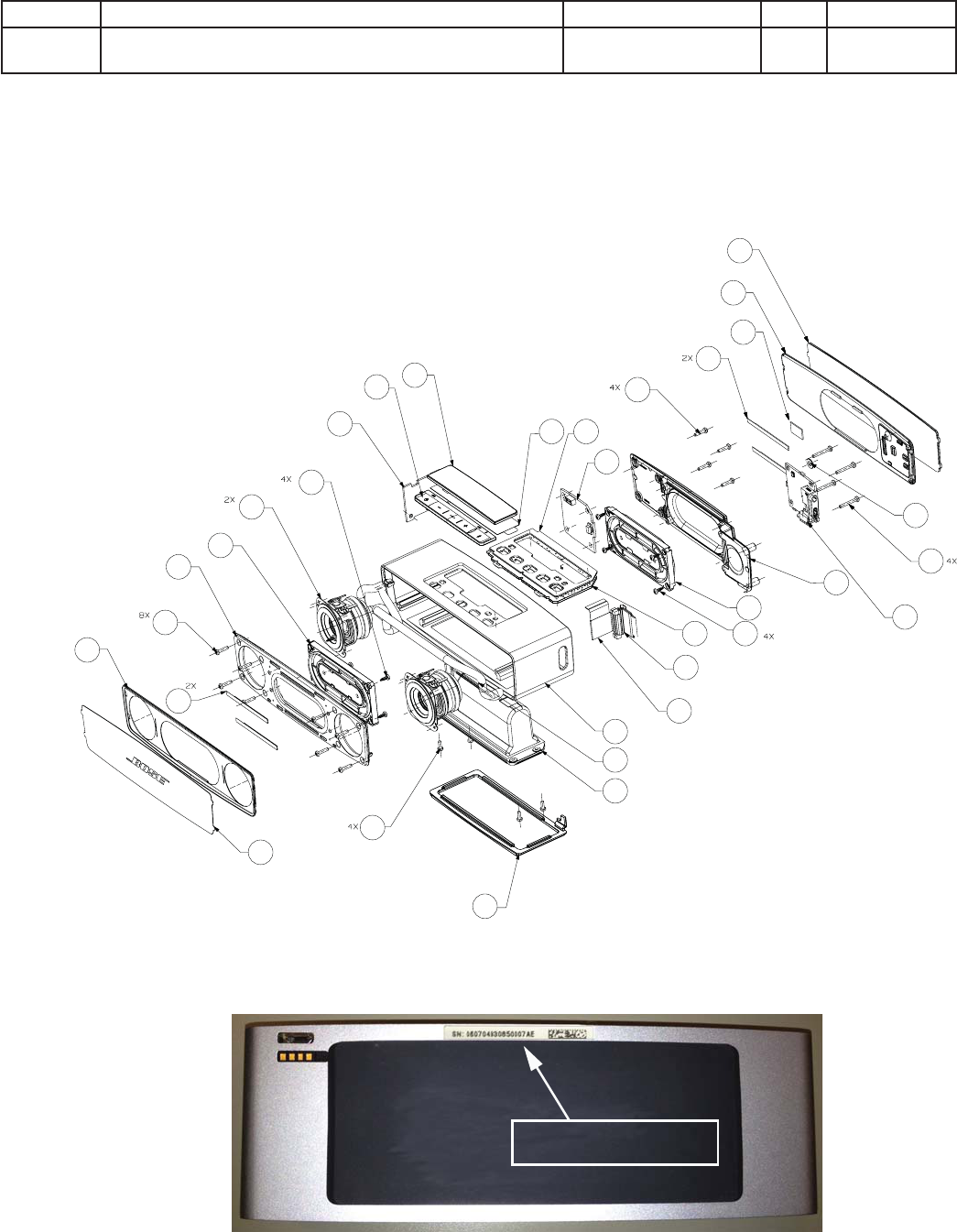
8
Place serial number label here
when replacing the foot.
8
9
10
11 12
13
14
7
6
5
4
3
1
30
31
32
2
21
22
2324
25
26
27
28
29
15
18
19
20
16
17
33
EXPLODED VIEW
Figure 2. SoundLink Mini II Main Assembly, Exploded View
SoundLink Mini II Serial Number Placement (when replacing the foot)
*The replacement foot/battery cover does not have a serial number
printed on it. Print the serial number on a small label and install on the unit above the foot. See Figure 2 on next page.
33 TAPE, FOAM 373978-0010 1
- VELCRO, 6MMX78MM, BLK (Use when replacing the Main
board - see service bulletin 725192-B2)
638167-1078 1

9
Reference
Designator
Description Material Number Note
R204
RES, 0402, 63MW, 1%, 100 OHM 268361-1000
R205 RES, 0402, 63MW, 1%, 100 OHM 268361-1000
R209 RES, 0402, 63MW, 1%, 4.99K 268361-4991
R211 RES, 0402, 0.063W, 1%, 30.1 OHMS 268361-30R1
R212 RES, 0402, 0.063W, 1%, 30.1 OHMS 268361-30R1
R213 RES, 0402, 0.063W, 1%, 30.1 OHMS 268361-30R1
R214 RES, 0402, 0.063W, 1%, 30.1 OHMS 268361-30R1
R215 JUMPER, 0402, 0 OHM 280043
R216 JUMPER, 0402, 0 OHM 280043
R217 JUMPER, 0402, 0 OHM 280043
R218 JUMPER, 0402, 0 OHM 280043
R219 JUMPER, 0402, 0 OHM 280043
R220 JUMPER, 0402, 0 OHM 280043
R221 RES, 0402, 63MW, 1%, 4.99K 268361-4991
R223 RES, 0402, 63MW, 1%, 4.99K 268361-4991
R224 JUMPER, 0402, 0 OHM 280043
R225 JUMPER, 0402, 0 OHM 280043
R226 JUMPER, 0402, 0 OHM 280043
R301 RES, 0402, 63MW, 1%, 1K 268361-1001
R303 JUMPER, 0402, 0 OHM 280043
R304 RES, 0402, 63MW, 1%, 100 OHM 268361-1000
R305 RES, 0402, 63MW, 1%, 100 OHM 268361-1000
R306 RES, 0402, 63MW, 1%, 4.99K 268361-4991
R307 RES, 0402, 63MW, 1%, 4.99K 268361-4991
R401 RES, 0805, .125W, 1%, 3.48K 133625-3481
R402 RES, 0805, .125W, 1%, 3.48K 133625-3481
R403 RES, 0402, 63MW, 1%, 249 OHM 268361-2490
R404 RES, 0402, 63MW, 1%, 249 OHM 268361-2490
R405 RES, 0402, 63MW, 1%, 249 OHM 268361-2490
R406 RES, 0402, 63MW, 1%, 249 OHM 268361-2490
R409 RES, 0402, 63MW, 1%, 1K 268361-1001
R410 RES, 0805, .125W, 1%, 475 133625-4750
R411 RES, 0805, .125W, 1%, 475 133625-4750
R412 RES, 0402, 63MW, 1%, 3.74 KOHM 268361-3741
R413 RES, 0402, 63MW, 1%, 3.74 KOHM 268361-3741
R414 RES, 0402, 63MW, 1%, 3.74 KOHM 268361-3741
R415 RES, 0402, 63MW, 1%, 3.74 KOHM 268361-3741
R416 RES, 0402, 63MW, 1%, 100 OHM 268361-1000
R417 RES, 0402, 63MW, 1%, 100 OHM 268361-1000
R503 RES, 0402, 0.063W, 1%, 46.4K 268361-4642
R504 RES, 0402, 63MW, 1%, 200 OHM 268361-200R
R505 RES, 0402, 0.063W, 1%, 46.4K 268361-4642
Main PCB
Resistors
ELECTRICAL PARTS LIST

10
Reference
Designator
Description Material Number Note
R506
RES, 0402, 63MW, 1%, 1K 268361-1001
R507 RES, 0603, .1W, 1%, 1 OHM 191465-01R0
R508 RES, 0603, .1W, 1%, 1 OHM 191465-01R0
R509 RES, 0603, .1W, 1%, 1 OHM 191465-01R0
R510 RES, 0603, .1W, 1%, 1 OHM 191465-01R0
R511 RES, 0603, .1W, 1%, 1 OHM 191465-01R0
R512 RES, 0603, .1W, 1%, 1 OHM 191465-01R0
R513 RES, 0603, .1W, 1%, 1 OHM 191465-01R0
R514 RES, 0603, .1W, 1%, 1 OHM 191465-01R0
R515 RES, 0603, .1W, 1%, 1 OHM 191465-01R0
R516 RES, 0603, .1W, 1%, 1 OHM 191465-01R0
R517 RES, 0402, 63mw, 1%, 2.49K 268361-2491
R518 RES, 0402, 63MW, 1%, 100K 268361-1003
R519 RES, 0402, 63MW, 1%, 1K 268361-1001
R520 RES, 0402, 63MW, 1%, 49.9 OHM 268361-49R9
R521 RES, 0402, 63MW, 1%, 100K 268361-1003
R522 RES, 0603, .1W, 1%, 150 OHMS 191465-1500
R523 RES, 0603, .1W, 1%, 150 OHMS 191465-1500
R524 RES, 0603, .1W, 1%, 150 OHMS 191465-1500
R525 RES, 0603, .1W, 1%, 150 OHMS 191465-1500
R526 RES, 0603, .1W, 1%, 150 OHMS 191465-1500
R527 RES, 0402, 63MW, 1%, 100K 268361-1003
R528 RES, 0402, 63MW, 1%, 2.21K 268361-2211
R531 RES, 0603, .1W, 1%, 1 OHM 191465-01R0
R602 RES, 0402, 63MW, 1%, 100K 268361-1003
R603 RES, 0402, 63MW, 1%, 10K 268361-1002
R604 RES, 0402, 0.063W, 1%, 332K 268361-3323
R605 RES, 0402, 63MW, 1%, 100K 268361-1003
R701 RES, 0402, 0.063W, 1%, 681K 268361-6813
R702 RES, 0402, 63MW, 1%, 1K 268361-1001
R703 RES, 0402, 63MW, 1%, 4.99K 268361-4992
R704 RES, 0402, 63MW, 1%, 64.9K 268361-6492
R705 RES, 0402, 63MW, 1%, 49.9K 268361-4992
R706 RES, 0402, 63MW, 1%, 64.9K 268361-6492
R707 RES, 0402, 63MW, 1%, 499 268361-499R
R708 RES, 0402, 63MW, 1%, 499 268361-499R
R709 RES, 0402, 0.063W, 1%, 30.1 OHMS 268361-30R1
R710 RES, 0402, 0.063W, 1%, 30.1 OHMS 268361-30R1
R711 RES, 0402, 0.063W, 1%, 30.1 OHMS 268361-30R1
R712 RES, 0402, 0.063W, 1%, 30.1 OHMS 268361-30R1
R713 RES, 0402, 0.063W, 1%, 30.1 OHMS 268361-30R1
R714 RES, 0402, 0.063W, 1%, 30.1 OHMS 268361-30R1
R715 RES, 0402, 63MW, 1%, 4.99K 268361-4991
ELECTRICAL PART LIST
Main PCB
Resistors (continued)

11
Reference
Designator
Description Material Number Note
R716
RES, 0402, 63MW, 1%, 4.99K 268361-4991
R717 RES, 0402, 63MW, 1%, 10K 268361-1002
R720 RES, 0402, 63MW, 1%, 4.99K 268361-4992
R721 RES, 0402, 63MW, 1%, 4.99K 268361-4992
R722 RES, 0402, 63MW, 1%, 2.21K 268361-2213
R723 RES, 0402, 63MW, 1%, 1M 268361-1004
R801 RES, 0402, 63MW, 1%, 1K 268361-1001
R802 RES, 0402, 63MW, 1%, 10K 268361-1002
R803 RES, 0402, 63MW, 1%, 10K 268361-1002
R805 RES, 0402, 63MW, 1%, 100 OHM 268361-1000
R806 RES, 0603, .1W, 1%, 20 OHM 191465-20R0
R807 RES, 0402, 63MW, 1%, 1K 268361-1001
R808 RES, 0402, 63MW, 1%, 100 OHM 268361-1000
R809 RES, 0402, 63MW, 1%, 10K 268361-1002
R810 RES, 0402, 63MW, 1%, 10K 268361-1002
R811 RES, 0402, 63MW, 1%, 10K 268361-1002
R812 RES ,0603, .1W, 1%, 20 OHM 191465-20R0
R813 RES, 0402, 63MW, 1%, 1K 268361-1001
R814 RES, 0402, 63MW, 1%, 100 OHM 268361-1000
R815 RES, 0402, 63MW, 1%,10 OHM 268361-10R0
R816 RES, 0603, 0.1W, 1%, 12OHMS 191465-12R0
R817 RES, 0402, 63MW, 1%, 1K 268361-1001
R819 RES, 0402, 63MW, 1%, 100 OHM 268361-1000
R820 RES, 0603, .1W, 1%, 33 OHM 191465-33R0
R825 RES, 0603, .1W, 1%, 75 OHM 191465-75R0
R827 RES, 0603, .1W, 1%, 75 OHM 191465-75R0
ELECTRICAL PART LIST
Main PCB
Resistors (continued)

12
Reference
Designator
Description Material Number Note
C302 CAP, X5R, 0402, 20%, 6.3V, 2.2uF 313771-225JM
C303 CAP, X5R, 0603, 2.2uF, 16V, 20% 313766-225C
C304 CAP, X5R, 0402, 20%, 6.3V, 2.2uF 313771-225JM
C305 CAP, X5R, 0402, 10V, 10%, 0.47uF 342199-474
C306 CAP, COG, 0402, 5%, 15pF, 50V 268364-150
C307 CAP, X7R, 0402, 50V, 5%, 10 nF 268366-103
C308 CAP, X7R, 0402, 50V, 5%, 10 nF 268366-103
C309 CAP, X5R, 0402, 10V, 10%, 0.47uF 342199-474
C310 CAP, X5R, 0402, 0.1uF, 16V, 10% 313771-104C
C311 CAP, X7R, 0402, 16V, 10%, 1000pF 293702-102
C312 CAP, X5R, 0402, 0.1uF, 16V, 10% 313771-104C
C314 CAP, X5R, 0402, 20%, 6.3V, 2.2uF 313771-225JM
C316 CAP, X5R, 0603, 4.7uF, 6.3V, 20% 313766-475J
C317 CAP, X5R, 0402, 0.1uF, 16V, 10% 313771-104C
C318 CAP, X7R, 0402, 16V, 10%, 1000pF 293702-102
C319 CAP, X7R, 0402, 16V, 10%, 1000pF 293702-102
C320 CAP, X7R, 0402, 16V, 10%, 1000pF 293702-102
C321 CAP, X7R, 0402, 16V, 10%, 1000pF 293702-102
C322 CAP, X7R, 0402, 16V, 10%, 1000pF 293702-102
C323 CAP, X7R, 0402, 16V, 10%, 1000pF 293702-102
C324 CAP, X5R, 0603, 2.2uF, 16V, 20% 313766-225C
C325 CAP, COG, 0402, 5%, 100pF, 50V 268364-101
C326 CAP, COG, 0402, 5%, 100pF, 50V 268364-101
C327 CAP, COG, 0402, 5%, 100pF, 50V 268364-101
C328 CAP, COG, 0402, 5%, 100pF, 50V 268364-101
C401 CAP, X7R, 0402, 16V, 10%, 1000pF 293702-102
C402 CAP, X7R, 0402, 16V, 10%, 1000pF 293702-102
C403 CAP, X7R, 0402, 16V, 10%, 1000pF 293702-102
C404 CAP, 1206, X7R, LD, 25V, 10%, 1uF 306105-105
C405 CAP, 1206, X7R, LD, 25V, 10%, 1uF 306105-105
C406 CAP, 1206, X7R, LD, 25V, 10%, 1uF 306105-105
C407 CAP, X7R, 0402, 50V, 5%, 1nF 268366-102
C408 CAP, X7R, 0402, 50V, 5%, 1nF 268366-102
C409 CAP, X7R, 0402, 16V, 10%, 1000pF 293702-102
C410 CAP, X7R, 0402, 16V, 10%, 1000pF 293702-102
C412 CAP, X7R, 0402, 16V, 10%, 1000pF 293702-102
C414 CAP, X7R, 0402, 10V, 10%, 0.1uF, COMM 718866-104K1A
C415 CAP, X7R, 0402, 16V, 10%, 1000pF 293702-102
C416 CAP, X7R, 0402, 16V, 10%, 1000pF 293702-102
C417 CAP, 1206, X7R, LD, 25V, 10%, 1uF 306105-105
C419 CAP, X7R, 0603, 1uF, 16V, 10% 257154-105K16
C420 CAP, X7R, 0402, 10V, 10%, 0.1uF, COMM 718866-104K1A
C421 CAP, X5R, 0603, 6.3V, 20%, 22uF, COMM 718835-226M0J
ELECTRICAL PART LIST
Main PCB
Capacitors

13
Reference
Designator
Description Material Number Note
C422 CAP, X7R, 0402, 10V, 10%, 0.1uF, COMM 718866-104K1A
C423 CAP, X7R, 0402, 16V, 10%, 1000pF 293702-102
C424 CAP, X7R, 0402, 16V, 10%, 1000pF 293702-102
C425 CAP, X7R, 0402, 10V, 10%, 0.1uF, COMM 718866-104K1A
C502 CAP, X7R, 0402, 16V, 10%, 0.1uF, COMM 718866-104K1C
C504 CAP, X7R, 0402, 16V, 10%, 0.1uF, COMM 718866-104K1C
C505 CAP, X7R, 0402, 16V, 10%, 0.1uF, COMM 718866-104K1C
C506 CAP, X7R, 0402, 16V, 10%, 10000pF, COMM 718866-103K1C
C507 CAP, CER, 1210, X7R, 25V, 10uF 291431-106
C508 CAP, 1206, X7R, 25V, 10%, 4.7uF 262063-475
C509 CAP, X7R, 0402, 16V, 10%, 0.1uF, COMM 718866-104K1C
C511 CAP, CER, 1210, X7R, 25V, 10uF 291431-106
C512 CAP, X7R, 0402, 16V, 10%, 0.1uF, COMM 718875-104K1C
C513 CAP, X7R, 0402, 16V, 10%, 1000pF, COMM 718866-102K1C
C603 CAP, X5R, 0805, 25V, 10%, 10uF 273592-106E
C604 CAP, 0805, X7R, 50V, 0.33uF 133623-334
C605 CAP, X5R, 0805, 22uF, 6.3V, 20% 273592-226JM
C608 CAP, X7R, 0402, 16V, 10%, 1000pF 293702-102
C610 CAP, X7R, 0402, 16V, 10%, 1000pF 293702-102
C701 CAP, X5R, 0805, 22uF, 6.3V, 20% 273592-226JM
C702 CAP, 0805, X7R, 10%, 25V, 1uF 181264-105
C703 CAP, X5R, 0402, 0.1uF, 16V, 10% 313771-104C
C704 CAP, X5R, 0402, 0.1uF, 16V, 10% 313771-104C
C705 CAP, X5R, 0402, 0.1uF, 16V, 10% 313771-104C
C706 CAP, X5R, 0402, 0.1uF, 16V, 10% 313771-104C
Diodes
Reference
Designator
Description Material Number Note
D401 DIODE, SWITCHING, 100V, BAV99, SOT363 319113-001
D402 DIODE, SWITCHING, 100V, BAV99, SOT363 319113-001
D403 DIODE, SWITCHING, 100V, BAV99, SOT363 319113-001
D502 DIODE, SCHOTTKY, 40V, 3A, SMB 193847-001
D503 DIODE, SCHTKY, SC70, 30V, SERIES 268381-004
D601 DIODE, SCHTKY, SC70, 30V, COM.CATH 268381-003
D602 DIODE, SCHTKY, SC70, 30V, COM.CATH 268381-003
D701 DIODE, SOT-23, BAV99 147239
D702 DIODE, SCHTKY, SC70, 30V, COM.CATH 268381-003
DS801 DIODE, LED, 0402, 0.01A, 5V, VERT, WHITE 373123-0010
DS802 DIODE, LED, 0402, 0.01A, 5V, VERT, WHITE 373123-0010
DS803 DIODE, LED, 0603, 0.20A, 5V, BLUE 728316-0020
DS805 DIODE, LED, 0402, 0.02A, 5V, GRN 364327-0020
DS807 DIODE, LED, 0402, 0.02A, 5V, YELLOW 367495-0020
DS808 DIODE, LED, 0402, 0.02A, 4V, RED 367495-0010
ELECTRICAL PART LIST
Main PCB
Capacitors Continued

14
Reference
Designator
Description Material Number Note
Q501 TRANSISTOR, MOSFET, P-CH, 0.3A, 30V, DMP32D4S 736331-0010
Q502 TRANSISTOR, BRT, NPN, 4.7K/47K, SOT-23 346223-0010
Q503 TRANSISTOR, BRT, NPN, 4.7K/47K, SOT-23 346223-0010
Q504 TRANSISTOR, MOSFET, P-CH, 4A, 20V, SOT-23 626239-0010
Q505 TRANSISTOR, BRT, NPN, 4.7K/47K, SOT-23 346223-0010
Q506 XSISTOR, BPLR, P, 40V, 200mA, SOT23 148596
Q601 XSISTOR, BPLR, N, 40V, 200mA, SOT23 146819
Q602 TRANSISTOR, MOSFET, P-CH, 0.3A, 30V, DMP32D4S 736331-0010
Q701 TRANSISTOR, MFET, N-CH, 0.3A, 60V, SOT-23 356154-0010
Q801 TRANSISTOR, BPLR, NPN, 0.2A, 40V, SOT-363 195857-3
Q802 TRANSISTOR, BPLR, NPN, 0.2A, 40V, SOT-363 195857-3
Q803 TRANSISTOR, BPLR, NPN, 0.2A, 40V, SOT-363 195857-3
Q804 TRANSISTOR, BPLR, NPN, 0.2A, 40V, SOT-363 195857-3
Integrated Circuits
Reference
Designator
Description Material Number Note
U200 IC, SoC,BLUETOOTH, W/DSP, CSR8670C, 112VFBGA 354008-0010
U202 IC, MEM, FLASH, SERIAL, 32Mb, 1.8V, 8SO 716603-0010
U501 IC, BATT CHRG, LI-ION, USB, 2-CELL, 5V, 20CSP 715728-0010
U602 IC, VREG, SW, BUCK, 0.5A, 3.3V, TPS62172, 8WSON 715991-0010
U701 IC, SoC, ARM, 32b, 85C, 4V, STM32F030C6, 48LQFP 715757-0020
Miscellaneous
Reference
Designator
Description Material Number Note
FB501 BEAD, FERRITE, 0603, 6A, 26 OHMS 345337-S026
FB502 BEAD, FERRITE, 0603, 6A, 26 OHMS 345337-S026
FL301 FILTER, SAW, 2.4GHz, BLUETOOTH, SON-5 331796-0010
J902 CONN, BRD-BRD, MALE, T ENTRY, 20POS, GRY 357552-0020
J903 CONN, FFC, 0.5mm, S ENTRY, 34POS 363842-34S2
L301 INDUCTOR, POWER, SMT, 85C, 1A, 20%, 4.7uH 627684-4R7M
L302 INDUCTOR, POWER, SMT, 85C, 1A, 20%, 4.7uH 627684-4R7M
L501 INDUCTOR, SMT, 6X6mm, 2.6A, 20%, 4.7uH 369623-4R7M
L601 INDUCTOR, POWER, SMT, 85C, 1.2A, 20%, 3.3uH 716046-3R3M
S801 SWITCH, TACT, SPST, 50mA, 12V, SMT 364142-0010
S802 SWITCH, TACT, SPST, 50mA, 12V, SMT 364142-0010
S804 SWITCH, TACT, SPST, 50mA, 12V, SMT 364142-0010
S805 SWITCH, TACT, SPST, 50mA, 12V, SMT 364142-0010
S806 SWITCH, TACT, SPST, 50mA, 12V, SMT 364142-0010
W201 JUMPER, 0402, 0 OHM 280043
W202 JUMPER, 0402, 0 OHM 280043
ELECTRICAL PART LIST
Main PCB
Transistors

15
Reference
Designator
Description Material Number Note
W301 JUMPER, 0402, 0 OHM 280043
W302 JUMPER, 0402, 0 OHM 280043
W402 JUMPER, 0402, 0 OHM 280043
W403 JUMPER, 0402, 0 OHM 280043
W404 JUMPER, 0402, 0 OHM 280043
W405 JUMPER, 0402, 0 OHM 280043
W408 JUMPER, 0402, 0 OHM 280043
W409 JUMPER, 0402, 0 OHM 280043
W412 JUMPER, 0402, 0 OHM 280043
W413 JUMPER, 0402, 0 OHM 280043
W414 JUMPER, 0402, 0 OHM 280043
W416 JUMPER, 0402, 0 OHM 280043
W703 JUMPER, 0402, 0 OHM 280043
W704 JUMPER, 0402, 0 OHM 280043
X301 CRYSTAL, 26MHz, +/-10ppm, SMD 291429-008
Reference
Designator
Description Material Number Note
R500 RES, 0402, 63MW, 1%, 100K 268361-1003
R501 RES, 0402, 63MW, 1%, 100K 268361-1003
R502 RES, 0402, 63MW, 1%, 22.1K 268361-2212
R505 RES, 0402, 63MW, 1%, 100K 268361-1003
R508 RES, 0402, 63MW, 1%, 100K 268361-1003
R509 RES, 0402, 33.2K, 1/16W, 1% 268361-3322
R510 RES, 0402, 63MW, 1%, 100K 268361-1003
R511 RES, 0402, 63MW, 1%, 280K 268361-2803
R512 RES, 0402, 63MW, 1%, 27.4K 268361-2742
R513 RESISTOR, JUMPER, 2A, 1206 319408-001
R514 RES, 0402, 63MW, 1%, 1.00K 268361-1001
R515 RES, METAL FOIL, 1206, 0.5W, 1%, 0.005 OHM 626686-R005F
R516 RES, 0402, 63MW, 1%, 10.0K 268361-1002
R517 RES, 0402, 63MW, 1%, 10.0K 268361-1002
R518 RES, 0805, 1/10W, 5%, 2.7 OHM 133626-2R75
R519 RES, 0402, 47.5K, 1/16W, 1% 268361-4752
R520 RES, 0402, 47.5K, 1/16W, 1% 268361-4752
R521 RES, 0402, 63MW, 1%, 499K 268361-4993
R522 RES, 0402, 63MW, 1%, 22.6K 268361-2262
R523 RES, 0402, 63MW, 1%, 3.01K 268361-3011
R524 RES, 0402, 63MW, 1%, 100 OHM 268361-1000
R525 RES, 0402, 63MW, 1%, 150K 268361-1503
R526 RES, 0402, 63MW, 1%, 499K 268361-4993
ELECTRICAL PART LIST
Main PCB
Miscellaneous Continued
Boost PCB Part List
Resistors

16
Reference
Designator
Description Material Number Note
C400 CAP, COG, 0402, 5%, 100pF, 50V 268364-101
C401 CAP, COG, 0402, 5%, 100pF, 50V 268364-101
C501 CAP, 0603, X7R, 50V, 10%, .033uF 191470-333
C502 CAP, COG, 0402, 5%, 100pF, 50V 268364-101
C503 CAP, C0G, 0402, 50V, 5%, 1.2nF 268364-122
C504 CAP, X5R, 0805, 25V, 10%, 10uF 273592-106E
C505 CAP, COG, 0402, 50V, 5%, 68pF 268364-680
C506 CAP, X7R, 0603, 1uF, 16V, 10% 257154-105K16
C507 CAP, X5R, 0805, 25V, 10%, 10uF 273592-106E
C508 CAP, X7R, 0603, 10%, 0.1uF, 50V 304991-104
C509 CAP, COG, 0402, 5%, 100pF, 50V 268364-101
C510 CAP, X5R, 0805, 25V, 10%, 10uF 273592-106E
C511 CAP, X5R, 0805, 25V, 10%, 10uF 273592-106E
C512 CAP, C0G, 0402, 50V, 5%, 1.5nF 268364-152
C513 CAP, X7R, 10UF, 25V, SMD, 125C, FT 315052-106D
C515 CAP, X7R, 0402, 25V, 5%, 3.3nF 268367-332
Diodes
Reference
Designator
Description Material Number Note
D500 DIODE, DUAL, 75V, 300mA, SOT-23 148774
D501 DIODE, SOT-23, BAV99 147239
D503 DIODE, SCHOTTKY, 10A, 40V, SMT 350300-0020
D504 DIODE, SCHTKY, SC70, 30V, SINGLE 268381-001
Transistors
Reference
Designator
Description Material Number Note
Q500 XISTOR, MFET, N-CH, 0.3A, 60V, 2N7002K, AUTO-Q 356154-0020
Q501 XISTOR, MFET, N-CH, 0.3A, 60V, 2N7002K, AUTO-Q 356154-0020
Q502 XISTOR, MFET, N-CH, 0.3A, 60V, 2N7002K, AUTO-Q 356154-0020
Q503 XISTOR, MOSFET, P-CH, 4A,20V, SOT-23 626239-0010
Q504 XISTOR, MFET, N-CH, 0.3A, 60V, 2N7002K, AUTO-Q 356154-0020
Q505 XISTOR, MFET, N-CH, 0.3A, 60V, 2N7002K, AUTO-Q 356154-0020
Q506 XISTOR, MFET, N-CH, 21A, 25V, 8SON 357501-0010
Q507 XISTOR, BPLR, P, 40V, 200mA, SOT23 148596
ELECTRICAL PART LIST
Boost PCB
Capacitors

17
Reference
Designator
Description Material Number Note
U500 IC, BOOST CONTROLLER, 4.5V TO 52V, 10SON 327304-0020
Miscellaneous
Reference
Designator
Description Material Number Note
J400 CONN, BRD-BRD, FEMALE, S ENTRY, 20 POS, GRY 357586-20S1
J401 CONN,BRD-BRD,FEMALE,S ENTRY,20 POS,GRY 357586-20S1
L500 INDUCTOR, SMT, 11.4X10.8mm, 13.6A, 20%, 2.2uH 628640-2R2M
Reference
Designator
Description Material Number Note
R200 RES, 0402, 63MW, 1%, 249 OHM 268361-2490
R201 RES, 0402, 63MW, 1%, 249 OHM 268361-2490
R202 RES, 0402, 63MW, 1%, 249 OHM 268361-2490
R203 RES, 0402, 63MW, 1%, 249 OHM 268361-2490
R300 RES, 0402, 63MW, 1%, 100K 268361-1003
R302 RES, 0402, 63MW, 1%, 100K 268361-1003
R303 RES, 0603, .1W, 1%, 20K 191465-2002
R304 RES, 0603, .1W, 1%, 100K 191465-1003
R305 RES, 0402, 63MW, 1%, 10 OHM 268361-10R0
R306 RES, 0402, 63MW, 1%, 1K 268361-1001
Reference
Designator
Description Material Number Note
C200 CAP, COG, 0402, 5%, 1000pF, 50V 268366-102
C201 CAP, COG, 0402, 5%, 1000pF, 50V 268366-102
C202 CAP, X7R, 0402, 50V, 10%, 1500pF, COMM 718866-152K1H
C203 CAP, X7R, 0402, 50V, 10%, 1500pF, COMM 718866-152K1H
C204 CAP, X7R, 0402, 50V, 10%, 1500pF, COMM 718866-152K1H
C205 CAP, X7R, 0402, 50V, 10%, 1500pF, COMM 718866-152K1H
C300 CAP, 1206, X7R, LD, 25V, 10%, 1.0uF 306105-105
C301 CAP, 1206, X7R, LD, 25V, 10%, 1.0uF 306105-105
C302 CAP, 1206, X7R, LD, 25V, 10%, 1.0uF 306105-105
C303 CAP, 1206, X7R, LD, 25V, 10%, 1.0uF 306105-105
C304 CAP, X7R, 0603, 1uF, 16V, 10% 257154-105K16
C305 CAP, 1206, X7R, 50V, 1uF, 10% 286500-105
C306 CAP, 0805, X7R, 50V, 10%, 0.22uF 133623-224
Capacitors
ELECTRICAL PART LIST
Boost PCB
Integrated Circuits
Amp PCB Part List
Resistors

18
Reference
Designator
Description Material Number Note
C307 CAP, 0805, X7R, 50V, 10%, 0.22uF 133623-224
C308 CAP, 0805, X7R, 50V, 10%, 0.22uF 133623-224
C309 CAP, 0805, X7R, 50V, 10%, 0.22uF 133623-224
C310 CAP, COG, 0402, 5%, 1000pF, 50V 268364-102
C311 CAP, COG, 0402, 5%, 1000pF, 50V 268364-102
C312 CAP, X7R, 0603, 10%, 0.1uF, 50V 304991-104
C313 CAP, X7R, 0603, 10%, 0.1uF, 50V 304991-104
C315 CAP, X7R, 0603, 10%, 0.1uF, 50V 304991-104
C317 CAP, X7R, 0603, 10%, 0.1uF, 50V 304991-104
C320 CAP, 1206, X7R, 50V, 1.0uF, 10% 286500-105
C321 CAP, 1206, X7R, 50V, 1.0uF, 10% 286500-105
C322 CAP, COG, 0402, 5%, 100pF, 50V 268364-101
C323 CAP, COG, 0402, 5%, 100pF, 50V 268364-101
C324 CAP, COG, 0402, 5%, 100pF, 50V 268364-101
C325 CAP, 1206, X7R, 50V, 1.0uF, 10% 286500-105
C327 CAP, COG, 0402, 5%, 100pF, 50V 268364-101
C328 CAP, X7R, 10uF, 25V, SMD, 125C, FT 315052-106D
C329 CAP, X7R, 10uF, 25V, SMD, 125C, FT 315052-106D
C330 CAP, X7R, 10uF, 25V, SMD, 125C, FT 315052-106D
Integrated Circuits
Miscellaneous
Reference
Designator
Description Material Number Note
FB300 BEAD, FERRITE, 1806, 6A, 100 OHM 722888-0010
FB301 BEAD, FERRITE, 1806, 6A, 100 OHM 722888-0010
FB302 BEAD, FERRITE, 1806, 6A, 100 OHM 722888-0010
FB303 BEAD, FERRITE, 1806, 6A, 100 OHM 722888-0010
J200 CONN, BRD-BRD, MALE, T ENTRY, 20POS, GRY 357552-0020
J300 CONN, HEADER, 4POS, 1.25mm, MALE, WHITE 330701-0004
Reference
Designator
Description Material Number Note
U300 IC, PWR AMP, CLASS D, 2X30W, 8 OHM, 32SO 356443-0010
3
؍
ELECTRICAL PART LIST
Amp PCB Part List
Capacitors (Continued)

19
Reference
Designator
Description Material Number Note
R702 RES, 0402, 47.5K, 1/16W, 1% 268361-4752
R703 RES, 0402, 63MW, 1%, 100K 268361-1003
R708 RES, 0402, 63MW, 1%, 100K 268361-1003
R713 RES, 0402, 63MW, 1%, 100K 268361-1003
R714 RES, 0402, 63MW, 1%, 100K 268361-1003
R715 RES, 0402, 63MW, 1%, 20.5K 268361-2052
R716 RES, 0402, 63MW, 1%, 20.5K 268361-2052
R717 RES, 0402, 63MW, 1%, 10.0K 268361-1002
R718 RES, 0402, 63MW, 1%, 23.7K 268361-2372
R719 RES, 0402, 63MW, 1%, 10.0K 268361-1002
R720 RES, 0402, 63MW, 1%, 10.0K 268361-1002
R721 RES, 0402, 63MW, 1%, 10.0K 268361-1002
R722 RES, 0402, 63MW, 1%, 100K 268361-1003
R723 RES, 0402, 63MW, 1%, 23.7K 268361-2372
R901 RES, 0805, 1/8W, 1%, 3.01K 173767-3011
R902 RES, 0805, 1/8W, 1%, 3.01K 173767-3011
R903 RES, 0402, 63MW, 1%, 100 OHM 268361-1000
R904 RES, 0402, 63MW, 1%, 100 OHM 268361-1000
Reference
Designator
Description Material Number Note
C601 CAP, 0805, COG, 50V, 5%, 180pF 133622-181
C701 CAP, X7R, 0402, 16V, 5%, 0.1uF, COMM 718866-104J1C
C703 CAP, X7R, 0402, 16V, 5%, 0.1uF, COMM 718866-104J1C
C704 CAP, X7R, 0402, 16V, 5%, 0.1uF, COMM 718866-104J1C
C705 CAP, X7R, 0402, 16V, 5%, 0.1uF, COMM 718866-104J1C
C706 CAP, X7R, 0603, 1uF, 16V, 10% 257154-105K16
C709 CAP, X7R, 0603, 1uF, 16V, 10% 257154-105K16
C801 CAP, X7R, 0402, 16V, 5%, 0.1uF, COMM 718866-104J1C
C902 CAP, X7R, 0402, 16V, 10%, 1000pF 293702-102
C903 CAP, COG, 0402, 5%, 180pF, 50V 268364-181
C904 CAP, X7R, 0402, 16V, 5%, 0.1uF, COMM 718866-104J1C
C905 CAP, X7R, 0402, 16V, 5%, 0.1uF, COMM 718866-104J1C
C906 CAP, 0805, COG, 50V, 5%, 180pF 133622-181
C909 CAP, X7R, 0402, 25V, 5%, 10nF 268367-103
C910 CAP, X7R,0603, 16V, 10%, 0.1uF 257154-104K16
C913 CAP, X7R, 0402, 16V, 10%, 1000pF 293702-102
Capacitors
ELECTRICAL PART LIST
I/O PCB Part List
Resistors

20
Reference
Designator
Description Material Number Note
D702 DIODE, SOT-23, BAV99 147239
D703 DIODE, SOT-23, BAV99 147239
D704 DIODE, SCHTKY, SC70, 30V, COM. CATH 268381-003
ZR701 DIODE, ZEN, 5.6V, 225MW, 5%, SOT-23 135247-5232
Transistors
Reference
Designator
Description Material Number Note
Q701 XSISTOR, BIAS, PNP, 0.03A, 50V, 47K/47K, SOT23 351912-0010
Q702 TRANSISTOR, MOSFET, P-CH, 4A, 20V, SOT-23 626239-0010
Q703 TRANSISTOR, MOSFET, P-CH, 4A, 20V, SOT-23 626239-0010
Q704 XSISTOR, BIAS, PNP, 0.03A, 50V, 47K/47K, SOT23 351912-0010
Q705 TRANSISTOR, MOSFET, P-CH, 4A, 20V, SOT-23 626239-0010
Q706 TRANSISTOR, MOSFET, P-CH, 4A, 20V, SOT-23 626239-0010
Q707 XSISTOR, BPLR, P, 40V, 200mA, SOT23 148596
Q708 BSS ASSY, SOUNDLINK MINI BT 2, IO 716542-0010
Integrated Circuits
Reference
Designator
Description Material Number Note
U701 IC, VOLTAGE COMPARATOR, LM339 187618-001
U901 MICROPHONE, MEMS, BOTTOM PORT, AKU440 728418-0010
Miscellaneous
Reference
Designator
Description Material Number Note
FB901 JUMPER, CHIP, 0603 196042
J901 CONN, CUSTOM, IO, 3.5MM, MICRO USB-B NG6 726796-0010
J903 CONN, FFC, 0.5mm, S ENTRY, 34POS 363842-34S2
J905 CONN, CUSTOM, BATTERY, 4POS, BLK 360718-0010
S801 IC, MUX/DEMUX, 2X2:1, USB, TS3USB221E, 10QFN 353620-0030
ELECTRICAL PART LIST
I/O PCB Part List
Diodes

21
DISASSEMBLY PROCEDURE
Important Notes!
*Place the system in “Ship Mode” prior to disas-
sembly by entering the TAP command “sh”.
See
TAP command set up on page 30.
Metal shavings might come out when removing
screws from the aluminum boss in the housing.
Effort must be taken to avoid metal shavings from
entering the unit. Use a vacuum to remove any
metal shavings.
1. Grille Removal
Note: The grille is held in place by Pressure Sensi-
tive Adhesive (PSA) strips located in the center of
the grille (fi gure 5.) and also by two tabs on either
end of the grille (fi gure 3).
To avoid destroying the grill during the removal
process, brush alcohol over the PSA strips (fi gure
5) before attempting to remove it.
Important Note: To avoid damage to the cabinet,
do not use the cabinet as a pry point to remove the
grille.
1.1 At the location shown in Figure 3, insert the tip
of a plastic tool, such as a spudger, between the
grille and its rubber gasket.
Note: The location shown is between the PSA and
grille tabs securing the grille.
1.2 Rotate the spudger away from you while prying
against the rubber gasket. Figure 4.
1.3 Once a portion of the grille is released, grasp
the grille and pull it across the unit lengthwise to
release the PSA. Figure 5.
2. Battery Removal
The Battery in SoundLink
®
Mini II is hardwired to
the Boost PCB. See fi gure 6. Place the product in
ship mode prior to disassembly. See entering ship
mode on page 33.
The rear grille, I/O PCB, rear baffl e and Amp PCB
must be removed before the Battery and Boost
board can be removed. Use the following procedure
to remove the battery and the boost board in order
to unsolder the cable and replace the battery.
Figure 3.
Figure 4.
Figure 5.
Figure 6.
Grille TABs
PSA Strips
Battery cable is soldered
to the Boost PCB

22
DISASSEMBLY PROCEDURE
Battery removal Removal (Continued)
2.1 Remove the foot by pulling it away from the
battery.
2.2 Remove the four screws securing the battery to
the cabinet. Figure 7.
2.3 Remove the four screws securing the I/O PCB
to the cabinet as shown in Figure 8.
2.4 Carefully peel away the foam tape securing the
FFC cable to the I/O PCB connector. This foam will
be damaged when removing, plan to replace the
foam with part number 373978-0010, see item 8 on
page 7.
Note: When handling the I/O board, do not to touch
the microphone fi lter with fi ngers. Gloves should be
used to avoid contact with the fi lter. Figure 8.
The replacement I/O PCB does not include the
microphone fi lter. Install new part (744588-0010)
when replacing the I/O PCB.
2.4 Move the I/O PCB to the right until the AUX
connector clears the housing and then lift the top
edge of the PCB until the USB connector clears the
housing. Figure 9.
2.5 Partially lift out the I/O PCB. Lift up the connec-
tor locking tab to release the FFC cable from the
I/O PCB connector.
2.6 Pull the battery cover out of the retaining slot in
the cabinet. Figure 9.
2.7 Remove the four screws securing the rear baf-
fl e. Figure 10.
Figure 7.
Figure 8.
Figure 9.
Figure 10.
Microphone
Filter
Foam Tape
Battery Cover Tab

23
DISASSEMBLY PROCEDURE
Battery removal Removal (Continued)
2.8 Lift the battery up and away from the enclo-
sure. The battery will still be connected to the boost
board but cannot be fully removed until the end of
the procedure.
2.9 As shown in Figure 11, insert your thumb into
the battery cavity and press upward on the rear
baffl e.
2.10 Hold the FFC against the transducer through
the battery opening while rocking the baffl e back/
forth as you slide it out of the cabinet. The FFC will
slide out of the slot in the rear baffl e while extract-
ing the baffl e in this way.
Note: Placing strain on the FFC Main PCB con-
nector can damage the connector if the FFC is not
held.
2.11 Using your thumb, push up on the Amp PCB
as shown in Figure 13 to release it from the boost
board.
2.12 Disconnect the speaker wire harness from the
AMP PCB.
2.13 Release the Boost board from the main board
connector by pushing upward. Figure 14, left.
2.14 Once the connector is unplugged, pull outward
on the boost board to release it from the slot. Figure
14, right.
2.15 Lift the battery away from the enclosure by
twisting the boost board to allow it to exit from the
assembly along with the battery.
Figure 11.
Figure 12.
Figure 13.
Figure 14.

24
Battery removal Removal (Continued)
2.16 Once the battery and boost board are removed
from the enclosure, the battery cable can be unsol-
dered and a new battery can be installed. Figure 15
shows the solder connections for the battery cable.
3. Driver Removal
3.1 Remove the eight screws securing the front
baffl e. Figure 16.
3.2 As shown in Figure 17, insert your thumb into
the back of the unit or the battery cavity and push
the front baffl e out of the cabinet.
3.3 Lift the left driver out of the cabinet. With a
plastic tool, such as a spudger, release the speaker
harness cable from the AMP PCB.
Figure 15.
Figure 16.
Figure 17.
Figure 18.
DISASSEMBLY PROCEDURE

25
4. Main PCB Removal
Important Note! To avoid damage to the switches
on the Main PCB, the front and rear baffl e should
be removed. The Main PCB is held in place by a
shelf on the front and rear baffl es which restricts
the ability of the Main PCB to be rotated downward
enough for the switches to clear the cabinet holes.
4.1 Perform procedures 1, 2, 3.1 and 3.2 to gain
access to the Main board.
4.1 Detach the speaker wire from the wire clip on
the main board.
4.1 lift upward on the main board and remove.
5. Lens Removal
5.1 Perform procedures 1, 2, 3 and 4 to gain ac-
cess to the lens
5.2 The Lens is held in place by Pressure Sensitive
Adhesive (PSA). Insert your thumbs into the cabinet
and press upward on the Lens to release the PSA.
Figure 20.
6. Button Pad Removal
5.1 Perform procedures 1, 2, 3 and 4 to gain ac-
cess to the button pad.
6.1 Insert a plastic tool, such as a spudger, under
the corner of the button pad and lift it up. Figure 21.
6.2 Peel up the button pad.
Figure 19.
Figure 20.
Figure 21.
DISASSEMBLY PROCEDURE

26
Speaker Terminals
Figure 22. Driver Placement
When assembling the unit, reverse the disassembly
procedures. The following assembly instructions
provide key points that are important to consider
when assembling the unit.
Note: To avoid stripping screws, fi rst rotate the
screw counter clockwise to locate the thread holes
and then clockwise to tighten.
1. Driver Installation
1.1 When installing the drivers, make sure to
place the speaker terminals toward the bottom.
Figure 22.
2. Speaker Harness Dressing
2.1 Run the speaker harness through the notch
in the Boost PCB. Figure 23.
2.2 The speaker harness should be dressed
taught under the clip on the Main PCB. This will
prevent the harness from contacting the moving
passive radiator when assembled. Figure 23.
Note: If the harness is too taught, the right driver
will rotate out of position.
Notch in
Boost Board
Clip on
Main PCB
Clip on
Main PCB
Figure 23. Driver Harness Dressing
ASSEMBLY KEY POINTS

27
Boost PCB
Slot
Figure 24. Boost PCB Slot
3. Boost Board Installation
3.1 When installing the Boost PCB, ensure the
board is placed in the PCB slot as you push
down on the board to connect it to the main
board. Figure 24.
4. Main and Boost PCB Placement
Note: A new FFC grommet should be used to
avoid potential air leaks.
Note: If the baffl e was removed, a new baffl e
should be used to avoid air leaks caused by
deformation of the baffl e wiper gasket. The
baffl e must be inserted straight down to prevent
the gasket from rolling under and causing an air
leak.
4.1 Insert the grommet over the FFC as shown.
Figure 25. FFC Grommet
4.2 Lower the Main PCB into the cabinet at an
angle so the switches do not scrape against the
cabinet. Then feed the boost board through the
top of the assembly and make the connection
between the boost board and the main board.
Feed the FFC with grommet through the slot
in the rear baffl e. Ensure both sides of the
grommet nub is fully seated in the slot. Figure 25
and 27.
4.3 The back edge of the Main PCB should rest
on the shelf of the rear baffl e. Figure 26.
4.4 Once fully inserted, rotate the front edge
of the Main PCB upward until the switches are
aligned to the holes in the cabinet.
4.5 With the speaker harness lined up with the
notch in the Boost PCB, rotate the Boost PCB
into position. Line up its connector with the
connector on the AMP PCB.
Note: Ensure the speaker harness is dressed
as described in the Speaker Harness Dressing
instructions procedure 2.
Grommet Location
Baffle Shelf
Grommit Nub
Figure 25. FCC Grommet
Figure 27. Grommet Seated in Baffl e Slot
Figure 26. Main PCB Placement
ASSEMBLY KEY POINTS

28
5. Securing the Baffl es - Gasket Pressure
5.1 When securing the screws indicated in
Figure 28, apply pressure at the points indicated.
The baffl e gasket provides an outward pressure
on the cabinet which must be counteracted when
securing the baffl e screws. Failure to do so will
result in an air leak.
6. Placing the I/O Connector Foam
6.1 The new foam covering the I/O cable needs
to be placed in the top left corner of the FFC
connector to avoid encroaching on the rear
gasket mic geometry.
6.2 When placing the foam, also check for the
presence of the mic fi lter.
7. Grille Replacement
Note: Remove all adhesive residue from the baffl e.
7.1 Align the replacement grille in the grille
gasket so the tabs protrude through the holes on
the edges. Figure 29 and 30.
7.2 Align the PSA with the front and rear baffl es
as shown in Figure 31.
7.3 Align the grille tabs with the cabinet and then
press down on the center of the grille. A roller
can be used to ensure the alignment features
on the grille gasket rest in the corresponding
features in the baffl e. Figures 29, 30, and 31.
Note: Failure to properly seat the grille gasket
alignment features will result in an uneven grille.
Refer to Figure 32 on the next page for gasket edge
alignment pictures.
! Important: The grille is considered a safety de-
vice and must be properly installed. To ensure the
PSA has been properly activated, a grille press is
needed to apply 30 PSI of pressure for 9 seconds
to the area of the grille secured by PSA.
Figure 28. Baffl e Gasket Compression
Pressure
Pressure
Pressure
Figure 29. Front Grille Gasket and Tabs
Figure 30. Rear Grille Gasket and Tabs
Alignment Features
Alignment Features
ADHESIVE STRIP, DIE CUT, GRILLE
729681-0010
Figure 31. PSA Location
ASSEMBLY KEY POINTS
I/O Connector Foam

29
Acceptable gasket alignment
Not acceptable gasket alignment
Not aceptable gasket alignment - gasket rolled over/pinched
The gasket should align fl ush within the cabinet edges. The Gasket does not need to have the same
fl ushness to the top and side cabinet edges.
Figure 32. Grille Gasket Alignment
ASSEMBLY KEY POINTS

30
USING TAP COMMANDS
Required Items
A. Polycomm interface tool - download “Polycomm.zip” from the SoundLink
®
Mini II page on the Bose
®
repair information website.
B. USB cable Type A to Micro B
Setup
1. Connect the USB cable to your computer and the SoundLink Mini II.
2. Unzip and Install the Polycomm application on your PC by clicking on the setup.exe fi le- this only needs
to be done once.
3. Open the Polycomm application. It should state “Connected” at the bottom of the application. If not con-
nected, click on the TAP Mode button.
4. Enter the TAP command VR to view the software version installed. A response indicates the unit is com-
municating in TAP mode.
Note: The Polycomm tool will only be used to issue TAP commands. Software updates should be per-
formed using the customer tool.
http://worldwide.bose.com
Figure 32. PolyComm Software tool for TAP

31
Equipment Required
Computer w/USB port
PolyComm Software
USB TYPE A to micro B cable
Audio frequency generator
Cell Phone with Bluetooth
®
Capabilities
USB current meter
Prior to the functional test, the integrity of the external
fl ash IC holding all non English languages should be
checked.
A. Factory default the product by pressing the power
button for 10 seconds until the LED’s turn off. Once the
button is released, voice prompts will ask you to select the
language.
B. Scroll through the different languages by pressing the
volume plus button. Then select a language.
The integrity of the fl ash IC is confi rmed if the different
languages can be heard.
1. Test Setup
1.1 Turn on the SoundLink
®
Mini II by pressing the
power button.
1.2 Run the Polycomm software and connect the USB
cable from the computer to the SoundLink Mini II. Then
select TAP mode.
2. Left/Right Driver/ AUX Input Test
2.1 Connect a signal generator to the left AUX input of
the Bose
®
Mini II Soundlink.
2.2 Adjust the signal generator to 50mVrms, 800Hz.
2.3 Issue TAP command VO 86 to set the volume to
60 (range is 0 to 99)
2.4 Confi rm audio plays from the left driver.
2.5 Connect the signal generator to the right AUX input
of the Soundlink Color.
2.6 Confi rm audio plays from the right driver.
3. Air Leak Test/ AUX Input Test
3.1 Connect a signal generator the AUX input of the
SoundLink Mini II.
3.2 Adjust the signal generator to 1.00Vrms, 60Hz.
3.3 Issue TAP command VO 86 to set the volume to
99 (range is 0 to 99)
3.4 Listen for air leaks around the cabinet edges and
keypad.
PASS if no audible air leaks can be heard at a distance
of less than 1 ft (0.3M).
FAIL if any audible air leaks can be heard at a distance
of less than 1 ft (0.3M).
4. Frequency Sweep Test/ AUX Input Test
4.1 Connect a signal generator to the AUX input of the
SoundLink Mini II.
4.2 Adjust the signal generator to 1.0Vrms, 50Hz.
4.3 Issue TAP command VO 99 to set the volume to
99 (range is 0 to 99)
4.4 Sweep the signal generator from 50Hz to 2kHz.
4.5 Listen for any extraneous noises such as buzzes,
rattles, ticks, or distortion.
PASS if no noise can be heard at a distance of less
than 1ft (0.3M).
FAIL if any noise can be heard at a distance less than
1ft (0.3M).
TEST PROCEDURES

32
5. Bluetooth
®
Functional Test
For this test, use a Cell phone with A2DP Bluetooth,
such as an iPhone
®
(Advanced Audio Distribution
Profi le)
Pair SoundLink Mini II and Bluetooth device.
Note: Make sure to remove the 3.5mm connector from
the AUX jack. The product switches to AUX when a
connector is inserted.
5.1 Remove power from the unit and turn on the
SoundLink Mini II.
Note: Removing power will test the units ability to play
audio from the battery also.
5.2 Press and hold the Bluetooth button until the LED
blinks blue to make the unit discoverable.
5.3 From the Bluetooth device list, select the device
named “Bose Mini II SoundLink”. Once paired, the
LED on the unit should turn a solid white and a voice
prompt will identify what device you have connected
to.
Note: If you are prompted for a pass code, enter 0000.
5.4 Play a familiar audio track from the Bluetooth
device.
5.5 Listen for a clean undistorted sound with no
audio drop outs.
6. Speakerphone Test
6.1 Using the cell phone, pair to the SoundLink Mini II
via Bluetooth.
6.2 Using a different phone, make a call to the
bluetooth connected cell phone.
6.3 The product will announce an incoming call.
Answer the call using the multifunction button.
6.4 Listen on the second phone as you talk into the
SoundLink Mini II for clear, undistorted audio from its
microphone.
Note: The microphone on the SoundLink Mini II is
located on a PCB mounted on the back right of the
product.
7. Battery Charging/ USB Port Test
7.1 Connect a USB current meter between the power
adapter and the SoundLink Mini II.
7.2 Confi rm the reading on the current meter is 1.5A.
Note: It is possible the reading will be a number less
than 1.5 if the battery is close to being fully charged.
7.3 Connect a USB current meter between a computer
and the SoundLink Mini II.
7.4 Confi rm the reading on the current meter is 0.5A.
Note: It is possible the reading will be a number less
than 0.5 if the battery is close to being fully charged.
8. Battery Level Check - Optional Test
8.1 Enter TAP command “ba 4” to read the battery
voltage level.
8.2 The results are returned in percentage of charge.
Example: The unit responds with 80 = 80% of a full
charge.
9. Battery Age Check
9.1 The battery is not able to supply age information
by TAP. Use the product’s Date Of Manufacture (DOM)
to estimate the battery age or the DOM printed on the
battery. The DOM is the 8th,9th,10th,11th number in
the serial number in the from YDDD.
Example: 4175 is the 175th day of 2104 or June 24th,
2014.
9.2 The battery should be less than 30 months old.
TEST PROCEDURES

33
TEST PROCEDURES
10. Factory Default Unit
Before returning the product to the customer, the unit
must be factory defaulted to remove any settings
that were changed during testing and also to clear
any test bluetooth devices from the pairing list. The
unit must then be placed into the ship mode to
prevent the unit from turning on during shipping from
an inadvertent button press.
10.1 Issue TAP command “fd” to factory default the
unit. The unit will respond with “OK”.
10.2 Issue TAP command “sh” to put the unit into
ship mode. The unit will respond with “OK”.
10.3 Disconnect the USB power cable from the
product.
10.4 Press the power button and ensure the
SoundLink Mini II does not turn on indicating it is in
the ship mode.
Note: The unit will not respond to button presses
while in the ship mode. When power is connected to
the unit, it will come out of ship mode and operate
normally.
11. Reading the Serial Number
The serial number for the SoundLink
®
Mini II is
located on the bottom foot. If the foot is missing or
the number is unreadable, use the TAP command
“sn 0” to read the serial number from the products
memory.
11. Additional TAP Commands
sh 99 - Reman Ship Mode; places the unit a special
remanufacturing mode. It should only be used for
units that will sit in storage for a period of time.
This command is used to drain the battery or charge
the battery, depending on how much the battery is
charged.
If the battery charge is to high, the LED’s will turn on
until the battery drains to a lower level, then goes
into ship mode.
If the battery has a charge is too low, the battery will
be charged to a higher level, then go into ship mode.
If the battery is ok for storage, then the battery will go
directly into ship mode.
Only perform the sh 99 command if the product
will be in storage for a long period of time. A typical
repair that will be sent back to a customer does not
require the command.
11.1 Connect power using the USB cable from the
computer to the SoundLink Mini II.
11.2 Press the power button to turn off the
SoundLink Mini II.
11.3 Issue TAP command “sh 99”.
11.4 Disconnect power.

34
Revision Date Description Page #
00 6/2015 Initial Release All
01 6/2015 Change sh 99 command. The product must be
turned off to execute this command.
pg 30
02 7/2015 New foot part number added 756361-0010
pg 7
03 8/2015
New front and rear baffl e part numbers
From 357404-0010 to 357404-0020
From 357405-0010 to 357405-0020
pg 7
04 9/2015
I/O, Amp and Boost boards changed.
from 716544-001S to 716544-002S PCB
ASSY, SOUNDLINK MINI BT 2, IO, SVCE
From 716527-001S to 716527-002S PCB
ASSY, KCUP, AMP, SVCE
From 716536-001S to 716536-002S PCB
ASSY, SOUNDLINK MINI BT 2, BOOST, SVCE
pg 7
05 9/2015
Added velco strip part number pg 8
06 10/2015
Foot part number added APAC pg 8
07 10/2015
Top Cap part number change from 728773 to
757367.
pg 8
08 10/2015
New part numbers for the shrink wrap pg 8
09 10/2015
Added bulk pack part numbers for grilles pg 8
10 12/2015
Add TAP command to retrieve serial number. pg 33
11 1/2016
Front grills had incorrect colors listed. pg 8
12 1/2016
Worldwide power supply changed from -0020
and -0021 to -0030 and -0031. Also added new
part number for main board - 755974-002S
pg 5
pg 7
SERVICE MANUAL REVISION HISTORY

Bose Corporation
100 The Mountain Road
Framingham Massachusetts USA 01701
Reference Number 725192-SM REV 12, 6/2015
http://serviceops.bose.com
