
GBA Global Bill Acceptors
GBA ST1C-UL
110 VAC
12Vdc
Operation Manual
This document is the copyright of Astrosys International Ltd. and may not be reproduced in total or in part
by any means, electronic or otherwise, without the prior written consent of Astrosys International Ltd.

GBA Global Bill Acceptors GBA ST1C -UL Operation Manual
Page 2 of 25 © Astrosys International Ltd
May 2017
GBA ST1C-UL Operation Manual V2.0.doc
CONTENTS
1 INTRODUCTION .......................................................................................... 3
1.1 Symbols ..................................................................................................................... 3
2 CARE AND TRANSPORT .............................................................................. 4
2.1 Transport ................................................................................................................... 4
2.2 Storage ...................................................................................................................... 4
2.3 Cleaning and Drying ................................................................................................... 4
2.4 Unpacking .................................................................................................................. 4
3 SAFETY DIRECTIONS & WARRANTY ............................................................ 5
3.1 General ...................................................................................................................... 5
3.2 Intended Use ............................................................................................................. 5
3.3 Responsibilities .......................................................................................................... 5
3.4 Warranty ................................................................................................................... 6
4 PRODUCT INFORMATION ........................................................................... 7
4.1 General Specifications ............................................................................................... 7
4.2 Product Architecture ................................................................................................. 8
4.3 Bill Cassette ............................................................................................................... 9
4.4 Opening the Bill Cassettes ....................................................................................... 10
4.5 Faceplate Options .................................................................................................... 11
4.6 Connections and User Controls ................................................................................ 12
4.7 Wiring Looms ........................................................................................................... 13
4.7.1 110VAC operation ...................................................................................... 13
4.7.2 12Vdc operation ........................................................................................ 13
4.7.3 Programming Loom (optional) ................................................................... 13
5 ELECTRICAL INTERFACE SPECIFICATION .................................................... 14
5.1 Power Requirements ............................................................................................... 14
5.2 Safety Standards ...................................................................................................... 14
5.3 110VAC Power Connector ........................................................................................ 15
5.3.1 9-pin connector Details .............................................................................. 15
5.3.2 Output Relay Rating ................................................................................... 15
5.3.3 High Voltage Enable ................................................................................... 15
5.4 12Vdc Low Voltage Signal Port ................................................................................. 16
5.4.1 18-pin Connector Details ............................................................................ 16
5.4.2 Low Voltage Enable .................................................................................... 16
5.4.3 Signal Specifications ................................................................................... 17
5.5 USB Port .................................................................................................................. 17
6 MAINTENANCE & OPERATION.................................................................. 18
6.1 Cleaning the Validator Bill Path ................................................................................ 18
6.2 Lower Sensor Housing ............................................................................................. 19
6.3 Clearing a Bill Jam .................................................................................................... 20
7 DIAGNOSTICS & TROUBLESHOOTING ....................................................... 21
7.1 Diagnostics .............................................................................................................. 21
7.1.1 Diagnostic LED ........................................................................................... 21
7.1.2 Diagnostic LED – Bill Reject Codes .............................................................. 22
7.1.3 Illuminated Bill Guide Patterns ................................................................... 22
7.2 Troubleshooting ...................................................................................................... 23
8 DIMENSIONAL DRAWINGS ....................................................................... 24
8.1 Upstacker / Downstacker ......................................................................................... 24
9 REVISION HISTORY ................................................................................... 25
9.1 Disclaimer ................................................................................................................ 25

GBA Global Bill Acceptors GBA ST1C -UL Operation Manual
Page 3 of 25 © Astrosys International Ltd
May 2017
GBA ST1C-UL Operation Manual V2.0.doc
Section
1
1 INTRODUCTION
This manual describes the operation and maintenance of the GBA ST1C-UL integrated
bill validator and stacker.
The GBA ST1C-UL bill acceptor has been specifically designed for use in UL
applications that require a 110VAC operation or 12Vdc and require to accept bill
widths up to 70mm.
The following features include:
Integral 100 - 120 Volt AC power regulator (for AC applications)
Up or Down entry stacking configuration
Fully illuminated Bill Entry Bezel
Easy access to bill path for cleaning and servicing
Cassette options for 100, 300, 600 or 1000 bills, with optional security locks
Two cassette styles offer front or rear note access
Multiple Interface Options
18 pin connector
Optional USB port for programming and connection to host controller
On board Individual bill enable / disable
UL and RoHS compliance
Please note that all references to “ST1C” in this document mean “ST1C-UL version
with integral 100 - 120 Volt AC power regulator”, where applicable.
If you have any questions about this or any other GBA and Microcoin products then
please visit our web sites at www.globalbillacceptors.com and www.microcoin.com,
or contact your regional sales office for assistance.
1.1 Symbols
The Symbols used in this manual have the following meanings:
Type
Description
Danger
Danger indicates an imminently hazardous situation which, if
not avoided, will result in death or serious injury.
Caution
Caution indicates a potentially hazardous situation or an
unintended use which, if not avoided, could result in death or
serious injury.
Warning
Warning indicates a potentially hazardous situation or an
unintended use which, if not avoided, may result in minor or
moderate injury and/or appreciable material, financial and
environmental damage.
Important paragraphs which must be adhered to in practice
as they enable the product to be used in a technically correct
and efficient manner.

GBA Global Bill Acceptors GBA ST1C -UL Operation Manual
Page 4 of 25 © Astrosys International Ltd
May 2017
GBA ST1C-UL Operation Manual V2.0.doc
Section
2
2 CARE AND TRANSPORT
2.1 Transport
Shipping
Whenever shipping the product, always use the original packaging,
shipping container and/or the appropriate packaging. The packaging
protects the product against potential shipping damage.
Inspection
After transport inspect the product before use.
2.2 Storage
Product
Respect the temperature limits when storing the equipment, particularly
in summer. Refer to section 4.1 General Specifications for information
about storage and operating temperature limits.
Inspection
After long periods of storage inspect the product before use.
2.3 Cleaning and Drying
Product
Use only a clean, soft, lint-free cloth for cleaning. If necessary, moisten
the cloth with water or a mix of water and up to 50% Iso-Propyl Alcohol
(IPA) . DO NOT use more than 50% IPA. Do not use other liquids; these
may attack surface coatings.
Please observe detailed instructions in section Error! Reference source
not found. Error! Reference source not found.
Damp products
Dry the product and the accessories at a temperature not greater than
40°C (108°F) and clean them. Do not repack until everything is
completely dry.
Cables and plugs
Keep plugs clean and dry. Blow away any dirt lodged in the plugs of the
connecting cables.
2.4 Unpacking
Inspect the Bill Acceptor for potential damage sustained in transit. If any damage is present,
return the ST1C-UL into the original packaging and notify the carrier immediately. Send a
written intent to file a claim to the delivering carrier within 72 hours from delivery. Send a
copy of that letter to the shipper. Note that only the consignee can file a claim against the
carrier for concealed damages.
If there was no damage sustained in transit, retain the original packaging for immediate
storage, future shipping or transporting.

GBA Global Bill Acceptors GBA ST1C -UL Operation Manual
Page 5 of 25 © Astrosys International Ltd
May 2017
GBA ST1C-UL Operation Manual V2.0.doc
Section
3
3 SAFETY DIRECTIONS & WARRANTY
3.1 General
The following directions should enable the person responsible for the product, and
the person responsible for use of the equipment, to anticipate and avoid operational
hazards.
The person responsible for the product must ensure that all personnel who install
and maintain the product understand these directions and adhere to them.
3.2 Intended Use
Permitted Uses
Bill Note Validation
Adverse Uses
Adverse uses of the equipment include, but are not limited to:
Use of the product without instruction
Use outside of the intended limits
Removal of hazard notices
Opening the product while it is connected to mains power
Modification or conversion of the product
Use of products with obviously recognizable damages or defects
Warning
Adverse use can lead to injury, malfunction and damage.
It is the task of the person responsible for the equipment to
inform the user about hazards and how to counteract them. The
product is not to be operated until the user has been instructed
on how to work with it.
3.3 Responsibilities
Person
installing or
maintaining
the product
The person installing or maintaining the product has the
following duties:
To understand the safety instructions on the product and the
instructions in the user manual
To be familiar with local regulations relating to safety and accident
prevention
To inform relevant person in charge immediately if the product and
the application becomes unsafe
To ensure that the national laws, regulations and conditions for the
operation are respected
Warning
The person installing the product must ensure that the product
is used for its intended purpose and that it is operationally safe.
Warning
This product may be installed only by an appropriately trained
and qualified technician as per any national regulation.
Warning
Only Astrosys International authorized service workshops are
entitled to repair these products.

GBA Global Bill Acceptors GBA ST1C -UL Operation Manual
Page 6 of 25 © Astrosys International Ltd
May 2017
GBA ST1C-UL Operation Manual V2.0.doc
3.4 Warranty
AstroSystems Inc warrants the GBA ST1C-UL Bill Acceptor for a period of one (1)
year from the date of purchase. This warranty extends to the original purchaser of
the warranted product, and to each transferee owner of the product, during the
term of the warranty.
During the warranty period, manufacturer will repair or replace (at manufacture’s
option); any parts (up to and including the complete unit) which fail to function
properly because of defects in material or workmanship.
This warranty covers the GBA ST1C-UL which has been designed to accept valid
currency. Manufacturer is not responsible for consequential damage or
performance degradation that results from counterfeit currency, foreign objects,
or other objects inserted into the Bill Acceptor.
The product to be repaired under warranty must be delivered to an Authorized
Service Centre, inbound freight prepaid. Upon request, owner must show proof of
purchase when submitting equipment for service during the warranty period.
Repair or installation at the owner’s location is NOT included in the warranty.
During the warranty period, manufacturer will pay all outbound ground freight
charges to the owner’s location. If special handling/shipping is desired, owner
must assume any shipping charges incurred.
Damage due to electrical overload, negligence, accidents, misuse, abuse,
vandalism, or act of God, is not covered by this warranty. Any alteration of the
product after manufacture voids the warranty in its entirety.
Manufacturer shall not be liable for any consequential damages as a result of
defects in material or workmanship. Any written or applied warranty of this product
is strictly limited to the refund of the cost of goods purchased.

GBA Global Bill Acceptors GBA ST1C -UL Operation Manual
Page 7 of 25 © Astrosys International Ltd
May 2017
GBA ST1C-UL Operation Manual V2.0.doc
Section
4
4 PRODUCT INFORMATION
4.1 General Specifications
Bill Insertion:
Up to 32 bill denominations with 4 way
insertion
Bill Dimensions:
62 to 70mm wide; 120 to 160 mm long
Bill Acceptance Rate:
Greater than 95%
Cycle Time for Validation and
Stack:
Typically less than 3 seconds
Nominal Cassette Capacity:
300 bills, front or rear access
Interfaces Supported:
Pulse
Parallel
NISR (Serial)
BSCP
ccTalk
ccNet
VCCS
Refer to separate manuals for more
details on each interface.
Power Supply:
110 Volt AC Nominally or 12Vdc
Environmental Range
(Operating Temperature):
0° to 55°C
(Operating Humidity):
Up to 90% R.H., non-condensing
(Storage Temperature):
-10° to 65°C

GBA Global Bill Acceptors GBA ST1C -UL Operation Manual
Page 8 of 25 © Astrosys International Ltd
May 2017
GBA ST1C-UL Operation Manual V2.0.doc
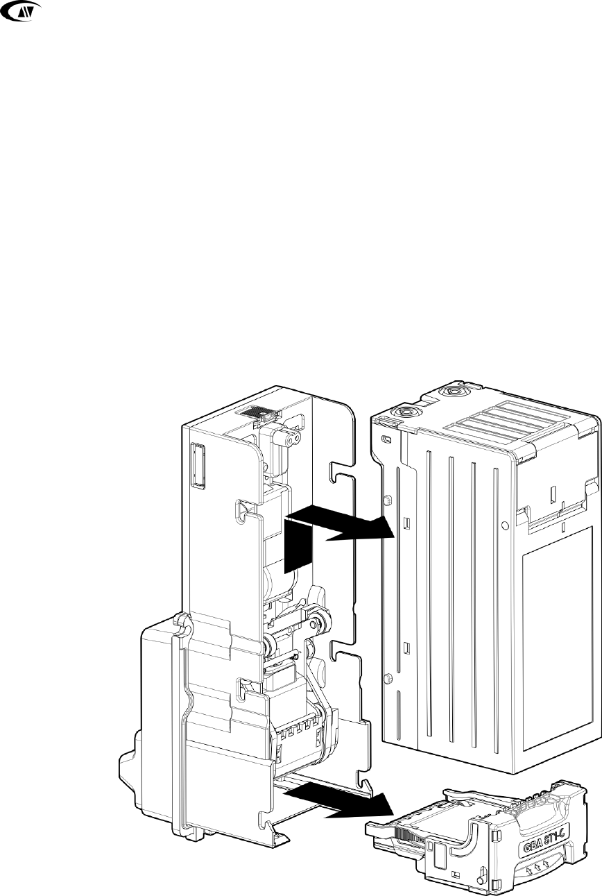
4.2 Product Architecture
The GBA ST1C-UL bill acceptor is a modular assembly which can be easily accessed for
service and support. It consists of a Main Chassis, Faceplate and Bill Guide, Bottom
Sensor Housing and a Bill Cassette. There are interchangeable items depending upon
the specific application.
① Bill Cassette (100, 300, 600 or 1000 bill capacity)
② Faceplate & matching Bill Guides to suit 66 or 70mm bill widths.
Internal Bill Guides to suit 66mm or 70mm applications
② Faceplate
& Bill Guide
Main Chassis
① Bill Cassette
(Front or rear access)
Bottom Sensor
Housing (With
Internal Bill
Guides)
Optional Cassette Lock
(located at rear for rear access
cassette)
4.2 Main components of product assembly

GBA Global Bill Acceptors GBA ST1C -UL Operation Manual
Page 9 of 25 © Astrosys International Ltd
May 2017
GBA ST1C-UL Operation Manual V2.0.doc
4.3 Bill Cassette
Bill cassettes can be provided with 100, 300, 600 or 1000 note capacity.
Each cassette may be supplied with tamper-evident security locks
The cassettes may be configured as front access or rear access styles for collecting
stored notes.
300 Bill Cassette shows a front access style
600 Bill Cassette shows a rear access style, with lock fitted
Remove the cassette by sliding
the cassette clip forwards and
lifting the cassette from the GBA
ST1C-UL unit.
Reverse this action to fit the
cassette back into place.
300 Bill Cassette
(showing front access)
600 Bill Cassette
(showing rear access)
style)

GBA Global Bill Acceptors GBA ST1C -UL Operation Manual
Page 10 of 25 © Astrosys International Ltd
May 2017
GBA ST1C-UL Operation Manual V2.0.doc
4.4 Opening the Bill Cassettes
To access the bills from each cassette
Front Access Cassette
Rear Access Cassette
Squeeze two tabs
Press the release button
Pull back to open the cassette lid
Remove stacked bills
Front Access Cassette
Opening lid
Front Access Cassette
Remove stacked bills
Rear Access Cassette
Opening Lid
Rear access Cassette
Remove stacked bills

GBA Global Bill Acceptors GBA ST1C -UL Operation Manual
Page 11 of 25 © Astrosys International Ltd
May 2017
GBA ST1C-UL Operation Manual V2.0.doc
4.5 Faceplate Options
The same faceplate is used for both 66mm bill guides and 70mm bill guides. The
design of the bill guide and faceplate is symmetric and it can be mounted in either up
or down stacking configuration.
Reminder: matching internal bill guides need to be mounted to the Lower Sensor Assembly
(refer section 6.2 ).
The validator can be mounted in three ways
(i) Standard - the entire faceplate is revealed at the front of the host machine
and can be used to mount information decals.
(ii) Security – only the raised area of the faceplate and the bill guide is
revealed
(iii) High security - just the illuminated bill guide is visible.
If you have a custom fitment application, do not hesitate to contact your local
regional office with your requirement.
4.5.2 Down stacker orientation
4.5.1 Up stacker orientation

GBA Global Bill Acceptors GBA ST1C -UL Operation Manual
Page 12 of 25 © Astrosys International Ltd
May 2017
GBA ST1C-UL Operation Manual V2.0.doc
4.6 Connections and User Controls
The GBA ST1C includes the following:
Item
Notes
8 pin port for 100 – 120 Volt AC
power and signals to the host
machine.
A connection cable is supplied with the
validator. See section 5.3 for more details
18 pin port for 12Vdc operation and
low voltage signals to the host
machine
See section 5.4 for more details
6 pin port for programming and
calibrating the validator
This requires a programming loom which
connects to a Microcoin VAL 364 USB to
Serial Dongle. See section 4.7
User Push Button and Diagnostic LED
See separate technical bulletin for more
details
USB port
See section 5.5 for more details
DIP Switch
See separate technical bulletin for more
details
Diagnostic LED
Push Button
USB Port
Programming Port
18-Pin Low Voltage
Signal Port
8-Pin Power
& Signal Port
4.6 - Location of connectors and user controls

GBA Global Bill Acceptors GBA ST1C -UL Operation Manual
Page 13 of 25 © Astrosys International Ltd
May 2017
GBA ST1C-UL Operation Manual V2.0.doc
4.7 Wiring Looms
4.7.1 110VAC operation
4.7.2 12Vdc operation
4.7.3 Programming Loom (optional)
ASY Part #
Description
Host Side Connector Part #
ASY-M-141403
110VAC Power & Signal Loom
AMP 9 Pin, c-172169-1
ASY-M-141404
Programming Loom
Connects to Microcoin VAL 364
ASY-M-141418
12Vdc Power & Signal Loom
Connects to 18 pin port
Power & Signal Loom Part # ASY-M-141403
Bill Acceptor Side
Host Side
Bill Acceptor Side
Host Side,
Unterminated
wires
12Vdc Loom Part # ASY-M-141418
Programming Loom
Part # ASY-M-141404
Microcoin
VAL 364
Bill Acceptor
Side
4.7 – Standard wiring looms
PC

GBA Global Bill Acceptors GBA ST1C -UL Operation Manual
Page 14 of 25 © Astrosys International Ltd
May 2017
GBA ST1C-UL Operation Manual V2.0.doc
Section
5
5 ELECTRICAL INTERFACE SPECIFICATION
Caution
ST1C-UL 110VAC is supplied from the mains voltage line; please
observe all applicable national and local legislations and
regulations during the installation and use of this device. It is the
sole responsibility of the customer to familiarize themselves with
the product and install it correctly.
Caution
ST1C-UL 110VAC needs to be powered from a current limited
supply that is adequately protected, taking into consideration local
installation wiring conditions
5.1 Power Requirements
Power Consumption (Typical):
15W
Supply Voltage:
100 to 120 Volts AC
Input current (Typical):
0.35A/115 Volts AC
5.2 Safety Standards
ST1C-UL 110VAC complies with the following regulations and directives:
Safety Standards:
UL60950-1
EMC Emission / Immunity:
EN55022: 2010
EN61000-3-3: 2008
EN55024 (EN61000-4-2):2010
EN55024 (EN61000-4-3):2010
EN55024 (EN61000-4-4):2010
EN55024 (EN61000-4-5):2010
EN55024 (EN61000-4-6):2010
EN55024 (EN61000-4-11):2010

GBA Global Bill Acceptors GBA ST1C -UL Operation Manual
Page 15 of 25 © Astrosys International Ltd
May 2017
GBA ST1C-UL Operation Manual V2.0.doc
5.3 110VAC Power Connector
5.3.1 9-pin connector Details
Connector on the wiring loom: TE Connectivity /Amp Mate-N-Lock 9-pin Female Pin
P/N 170362-1, with male crimps P/N 172169-1
Pin
Function
1
120 VAC Neutral Inhibit.
2
120 VAC Neutral Enable.
3
120 VAC Hot Enable.
4
120 VAC Hot Power
5
No Connection
6
120 VAC Neutral Power
7
Bill Acceptor Relay Contact (Normally Open)
8
Bill Acceptor Relay Contact (Common)
9
No Connection
Ground
Ring terminal should be screwed to the
grounded frame
5.3.2 Output Relay Rating
CONTACTS Ratings
(Resistive load):
Max. switched power: 30 W or 250 VA
UL Rating:
2 A at 125VAC General Use
1 A at 30 VDC Resistive
GENERAL DATA
Life Expectancy Minimum operations
Electrical 1 x 10
5
at 2 A 120 VAC Res.
Operate Time (typical) 5 ms at nominal coil voltage
Release Time (typical) 1 ms at nominal coil voltage
(with no coil suppressions)
Note 1): All values at 20°C (68°F).
Note 2): Please observe AWG current carrying capacity limits.
5.3.3 High Voltage Enable
The ST1C can be enabled or inhibited using the 9-pin connector as follows:
Pin
Function
1
110 VAC Neutral Inhibit.
Connect to 120 VAC Neutral to disable
acceptor. If this is left floating, it may disable
acceptor, based on the state of the 120VAC Hot
Enable line.
2
110 VAC Neutral Enable.
Connect to 120 VAC Neutral to enable acceptor.
Leave floating to disable acceptor.
3
110 VAC Hot Enable.
Connect to 120 VAC Hot to enable acceptor.
Leave floating to disable acceptor.
Note: You should connect only one of these three pins.
Power & Signal
Loom Connector
(Host Side)
1
7
3
9

GBA Global Bill Acceptors GBA ST1C -UL Operation Manual
Page 16 of 25 © Astrosys International Ltd
May 2017
GBA ST1C-UL Operation Manual V2.0.doc
5.4 12Vdc Low Voltage Signal Port
5.4.1 18-pin Connector Details
Recommended mating connector: TE Connectivity / Amp - 5-102398-7 - Connector,
Header, IDC, 2.54mm, 18way
Pin
Function
Pin
Function
1
Out
Credit Pulses
(1)
10
Out
Alarm
2
Out
Ready To Send for Serial
Mode
11
12 Volt DC Input
(6)
3
In
Serial / Pulse Select Line
12
In
Enable Validator
(3)(2)
4
DC Ground
13
Out
Power for Alarm LED
5
Out
Transmit (TTL level
RS232)
14
In
Serial – Ready to Send or
Receive (TTL level RS232)
6
Out
Parallel Vend Channel 1
15
Out
Parallel Vend Channel 5
7
Out
Parallel Vend Channel 2
16
In
Alternate Receive (TTL level
RS232)
(5)
8
Out
Parallel Vend Channel 3
17
Out
Parallel Vend Channel 6
9
Out
Parallel Vend Channel 4
18
In
Parallel Escrow Control
(4)
Notes:
1. All outputs pull the pin to ground when active
2. When using Low Voltage Enable input on this connector, do not connect High
Voltage Enable pins to avoid conflicts in the control logic. See table below
3. The Enable Validator input can be configured for Active Low (validator is in
service when the input is pulled to ground) or Active High. If the ST1C is fitted
with a DIP switch, this input can be over-ridden by the “Always Enable” switch.
4. The Escrow Control Input is always configured as Active Low
5. For serial protocols, the data line can be connected to either pin 14 or 16
6. The 12 Volt DC input is provided for low voltage operation only.
5.4.2 Low Voltage Enable
The logic for the Enable Validator input on pin 12 is:
Condition
Input status
Validator Status
Active Low
Low
Enabled
Disconnected
Inhibited
High
Inhibited
Active High
Low
Inhibited
Disconnected
Inhibited
High
Enabled
1
10
9
18
View looking at the validator

GBA Global Bill Acceptors GBA ST1C -UL Operation Manual
Page 17 of 25 © Astrosys International Ltd
May 2017
GBA ST1C-UL Operation Manual V2.0.doc
5.4.3 Signal Specifications
Open Collector outputs:
Maximum Open Voltage
40V
Maximum Sink Current
50mA @ 12VDC
Maximum Output Low Voltage:
0.4VDC
Minimum Output High Voltage:
2.4VDC
Input low level voltage:
0…. 1V
Input high level voltage:
3…..12V (typically 3… 5V)
Input pull up to 5V:
21K Ω
5.5 USB Port
The ST1C USB port is compliant as a USB 2.0 full speed host or device and is fitted
with a mini-AB socket. The USB port can be used to:
Connect a USB memory device to reprogram the validator with new firmware
and bill dataset
Connect to a USB port on the machine controller. The validator will enumerate as
a serial port device for compatibility. Please contact your local regional office for
the relevant device drivers.
5.5 USB Mini-A or Mini-B Cable

GBA Global Bill Acceptors GBA ST1C -UL Operation Manual
Page 18 of 25 © Astrosys International Ltd
May 2017
GBA ST1C-UL Operation Manual V2.0.doc
Section
6
6 MAINTENANCE & OPERATION
6.1 Cleaning the Validator Bill Path
Equipment Required
1.
Cotton swab or a lint-free cloth.
2.
Cleaning solution: A mix of water and up to 50% Iso-Propyl Alcohol
(IPA) is recommended.
DO NOT use more than 50% IPA. NEVER use solvent-based
cleaning agents, such as Amberclens, pure alcohol, petrol,
methylated spirit or white spirit on this product as the unit will be
severely damaged.
1. Ensure the power supply to the GBA ST1C unit is switched OFF.
2. Remove the Cassette.
3. Lift up the purple Access Latch on the back of the Lower Sensor Assembly, and
gently slide the module out of the Channel Assembly – see section 6.2.
4. Using a cotton swab, or lint-free cloth, wetted with cleaning solution and
applying light force only, carefully clean all sensor windows in both halves
(upper and lower) of the bill path. If a sensor window has become badly
scratched do not attempt to polish it, contact your local regional office for
further advice.
5. Continue with the swab, or lint-free cloth, to clean the rest of the bill path,
including sprung rollers.
6. Visible parts of belts can be cleaned by wiping with a cleaning solution-soaked
cotton swab or wipe. It is not possible to clean the whole belt surface without
removing the belts from the unit.
7. Use an additional swab or cloth to dry the cleaned area, if required.

GBA Global Bill Acceptors GBA ST1C -UL Operation Manual
Page 19 of 25 © Astrosys International Ltd
May 2017
GBA ST1C-UL Operation Manual V2.0.doc
6.2 Lower Sensor Housing
The lower sensor assembly has an internalised connection to the main chassis, so
there is no cable to disconnect. To remove the housing lift the access latch and gently
slide back.
To refit the assembly, slide it forward until the retaining bar clicks into place.
Note that the black internal bill guides must be fitted for either 66 or 70mm
applications. They can be provided as a kit, which includes a matching note guide.
Internal Bill Guides
Two options matched with
the external bill guides:
66mm kit
ASY-M-111445
70mm kit
ASY-M-111446
Access Latch
6.2 Image of Lower Sensor Assembly
GBA Global Bill Acceptors GBA ST1C -UL Operation Manual
Page 20 of 25 © Astrosys International Ltd
May 2017
GBA ST1C-UL Operation Manual V2.0.doc
6.3 Clearing a Bill Jam
1. Ensure the power supply to the GBA ST1C-UL unit is switched OFF.
2. Remove the Cassette.
3. Lift up the purple Access Latch on the back of the Bottom Sensor Assembly,
and gently slide the module out of the Channel Assembly.
4. Clear the jammed bill(s) from the bill acceptor.
5. Re-assemble unit and switch the power supply back ON.
6.3 - Image of bill path access

GBA Global Bill Acceptors GBA ST1C -UL Operation Manual
Page 21 of 25 © Astrosys International Ltd
May 2017
GBA ST1C-UL Operation Manual V2.0.doc
Section
7
7 DIAGNOSTICS & TROUBLESHOOTING
7.1 Diagnostics
7.1.1 Diagnostic LED
The GBA ST1C has the facility to communicate validator status by the use of a tri
coloured Diagnostic LED located on the side of the unit. This enables enhanced
diagnostics for the user and for factory personnel when assisting customers over the
phone or by email. The following functionality describes the operation of the LED:
Indication
Status
Standby Modes
Steady Green
Unit Operational
Steady Orange
Unit Inhibited by Host Controller
Steady Red
Unit out of order – Hard Fault
Active Modes
Flashing Green
Unit Validating
Flashing Red
Soft Fault – Check Unit (e.g. stacker full)
Flashing Orange
Sensors read low – clean lenses
Program Modes
Fast Flashing Green
Bill Enable – Programming Mode
Fast Flashing Red
Bill Disable – Programming Mode
Fast Flashing Orange
Primary Calibration – Programming Mode
7.1 Image of side view of ST1C showing diagnostic LED
Diagnostic
LED

GBA Global Bill Acceptors GBA ST1C -UL Operation Manual
Page 22 of 25 © Astrosys International Ltd
May 2017
GBA ST1C-UL Operation Manual V2.0.doc
7.1.2 Diagnostic LED – Bill Reject Codes
If a bill is rejected then a flash code is given when the bill is removed (the LED will
flash red or orange a number of times):
Cause of Bill Rejection
Number of flashes
Unrecognised bill
1 Red
Optical Anti String Gate was triggered
2 Red
Bill Inhibited in the configuration or by DIP switch
3 Red
Bill Inhibited by the Host
3 Orange
Bill slipped or was held by the user as it was scanned
4 Red
Bill inserted skewed
5 Red
Bill is too long or two bills inserted
6 Red
7.1.3 Illuminated Bill Guide Patterns
The illuminated bill guide can be configured to flash different patterns according to
the validator state. The standard patterns are:
ST1C State
Pattern
Out of Service - fault
Bill Guide off
Not accepting bills at the request of the host
controller
Flashes momentarily every
2.5 seconds
In service, waiting for a bill
Bill Guide on
In service, handling a bill
Flashes continuously

GBA Global Bill Acceptors GBA ST1C 110VAC Operation Manual
Page 23 of 25 © Astrosys International Ltd
June 2014
GBA ST1C-UL Operation Manual V2.0.doc
7.2 Troubleshooting
The following information is presented for customers’ guidance in identifying problems with the GBA ST1C. It does not necessarily cover every
possible situation.
Problem Symptoms
Possible Cause
Investigate
Possible Solution
Unit does not work when power is
applied - belt motor does not run, status
LED is off, and illuminated bill guide is
off.
1. Power supply not switched on.
2. Power supply not connected.
3. Poor electrical connection(s).
4. Unit is in “Low Power” mode and is
waiting for a bill to be inserted
1. Power supply and power cable.
2. Diagnostics indicator or illuminated bill
guide.
3. Interface cable assemblies.
4. Insert a bill and check if the ST1C starts
up.
1. Ensure power to validator is connected
and turned on.
2. Ensure Interface cable is connected
firmly and correctly.
All programmed bills are rejected
1. Acceptance inhibited for all bills.
2. Optical Sensors damaged or dirty
3. “Ready To Punch” sensor not working.
1. Software configuration.
2. Remove Bottom Sensor Assembly and
inspect
1. Use on-board button or GBA Talk to
enable required bills.
2. Clean lenses in bill path. Then
recalibrate the validator.
Poor or no acceptance of one or more
programmed bills
1. Bill acceptance inhibited.
2. Poor sensor readings.
3. Insufficient power supply capacity.
1. Bill inhibit settings.
2. Bottom Sensor Assembly fitting.
3. Bill path cleanliness.
1. Use on-board button or GBA Talk to
enable required bills.
2. Use GBA Talk to check sensor levels and
re-calibrate if necessary.
3. Clean validator bill path.
Bills fail to stack correctly
1. “Ready To Punch” sensor not working.
2. Stacker motor not working.
3. Stacker mechanism not working.
1. Stacker motor cable connections.
2. Stacker jams.
3. Damaged / distorted bill in cassette.
1. Ensure all cables are connected
properly.
2. Ensure cassette is located correctly and
free from damage.
Unit does not communicate with host
machine
1. Incorrect interface selected.
2. Poor electrical connection(s).
1. Configuration of validator.
2. Interface cable assembly.
1. Use on-board button or GBA Talk to
select required interface.
2. Ensure Interface is connected firmly
and correctly.
Belt motor and/or stacker motor runs
continuously after power ON
1. Poor electrical connection(s)
1. Internal harnessing.
1. Ensure Interface cable is connected
firmly and correctly.
Unit does not provide credit for
accepted bill
1. Incorrect interface selected.
2. Poor electrical connection(s).
1. Configuration of validator.
2. Interface cable assembly.
1. Use on-board button with Program
Card or GBA Talk to select required
interface.
2. Ensure Interface cable is connected
firmly and correctly.
GBA Global Bill Acceptors GBA ST1C 110VAC Operation Manual
Page 24 of 25 © Astrosys International Ltd
June 2014
GBA ST1C-UL Operation Manual V2.0.doc
Section
8
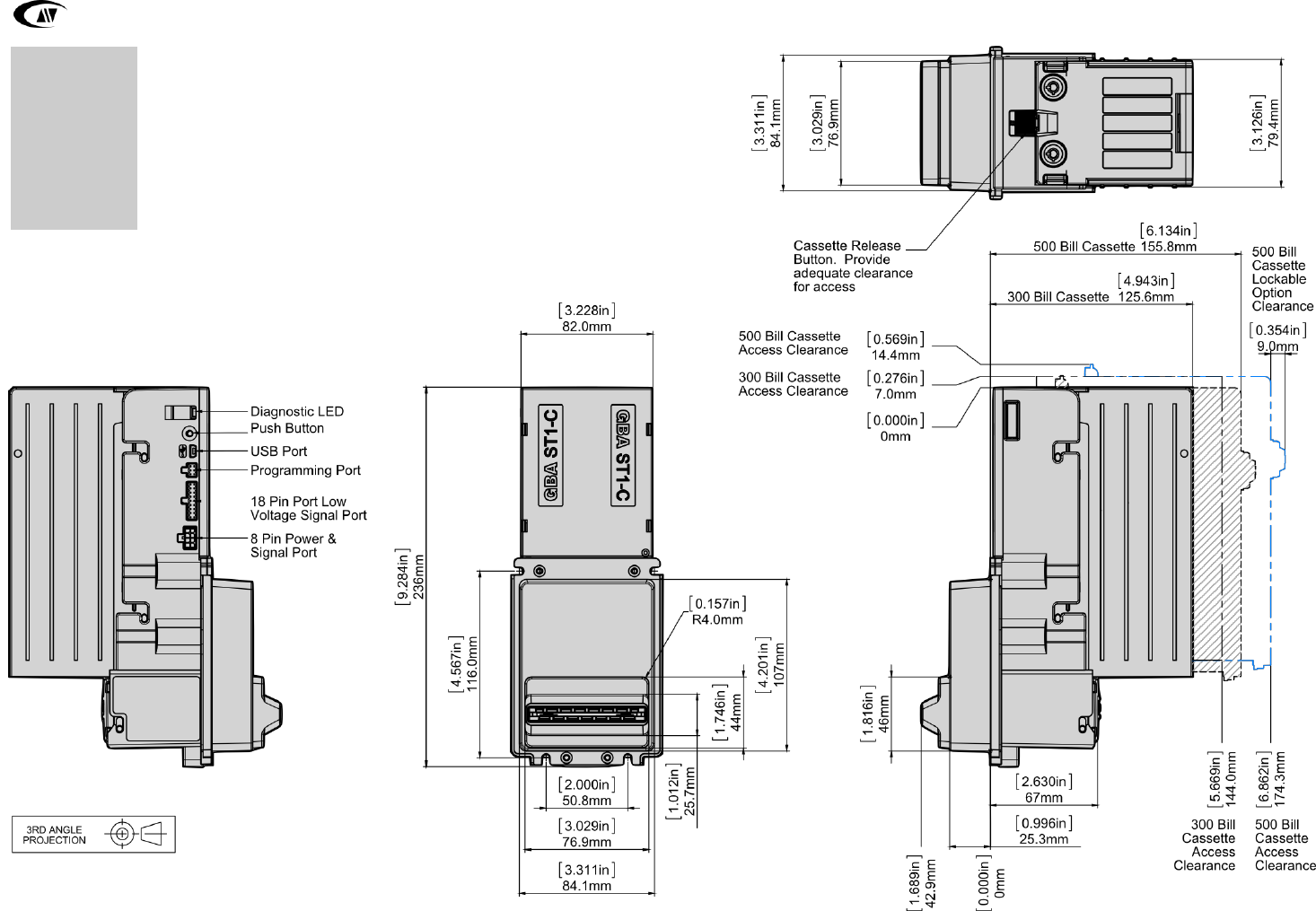
8 DIMENSIONAL DRAWINGS
8.1 Upstacker / Downstacker

GBA Global Bill Acceptors GBA ST1C 110VAC Operation Manual
Page 25 of 25 © Astrosys International Ltd
June 2014
GBA ST1C-UL Operation Manual V2.0.doc
Section
9
9 REVISION HISTORY
Revision
Date
Created
Approved
Comments
1.0
19-Mar-14
Steve Lewis /
Nikola Korecki
Initial issue.
2.0
24 May 2017
RB
Updated issue
9.1 Disclaimer
Astrosys International Ltd. reserves the right to amend, improve or otherwise change
this document or the product referred to herein at any time.
Astrosys International Ltd. does not accept liability for any errors contained within, or
omissions from, this document. Astrosys International Ltd. shall not incur any
penalties arising from the adherence to, reliance on or interpretation of this
document.
Regional Offices
AstroSystems Inc.
Microsystem Controls Pty Ltd
4210 Production Court
Unit D2.0 Ground Floor
Las Vegas
63-85 Turner Street
Nv 89115
Port Melbourne
USA
Victoria 3207
Australia
Tel: +1 702 643 1600
Tel: +613 9646 6446
Fax: +1 702 643 1717
Fax: +613 9646 6447
E-mail: [email protected]om
E-mail: [email protected]
AstroSystems Ltd.
AstroSystems (Far East) Ltd.
1 The Quadrangle
2/F 28 Hung to Road
Grove Technology Park
Kwun Tong
Wantage
Kowloon
Oxon. OX12 9FA
Hong Kong
U.K.
Tel: +44 (0) 1235 772201
Tel: +852 2342 6123
Fax: +44 (0) 1235 772202
Fax: +852 2342 6105
E-mail: [email protected]o.uk
E-mail: [email protected]
