
QII53029-11.1.0
© 2011 Altera Corporation. All rights reserved. ALTERA, ARRIA, CYCLONE, HARDCOPY, MAX, MEGACORE, NIOS, QUARTUS and STRATIX words and logos
are trademarks of Altera Corporation and registered in the U.S. Patent and Trademark Office and in other countries. All other words and logos identified as
trademarks or service marks are the property of their respective holders as described at www.altera.com/common/legal.html. Altera warrants performance of its
semiconductor products to current specifications in accordance with Altera's standard warranty, but reserves the right to make changes to any products and
services at any time without notice. Altera assumes no responsibility or liability arising out of the application or use of any information, product, or service
described herein except as expressly agreed to in writing by Altera. Altera customers are advised to obtain the latest version of device specifications before relying
on any published information and before placing orders for products or services.
Quartus II Handbook Version 11.1
Volume 3: Verification
November 2011
Feedback SubscribeTwitter
ISO
9001:2008
Registered
11. Transceiver Link Debugging Using the
System Console
This chapter describes how to use the Transceiver Toolkit in the Quartus
®
II software.
The Transceiver Toolkit in the Quartus II software allows you to quickly test the
functionality of transceiver channels and helps you improve the signal integrity of
transceiver links in your design.
1 You can use an example design available on the Altera
®
website if you want to
immediately start using the Transceiver Toolkit, or you can create a custom design.
In today's high-speed interfaces, stringent bit error rate (BER) requirements are not
easy to meet and debug. You can use the Transceiver Toolkit in the Quartus II software
to check and improve the signal integrity of transceiver links on your board before
you complete the final design, saving you time and helping you find the best physical
medium attachment (PMA) settings for your high-speed interfaces.
This chapter contains the following sections:
■ “Transceiver Toolkit Overview”
■ “Transceiver Link Debugging Design Examples” on page 11–3
■ “Setting Up Tests for Link Debugging” on page 11–3
■ “Using Tcl in System Console” on page 11–13
■ “Usage Scenarios” on page 11–14
■ “Quick Guide to Using the Transceiver Toolkit in the Quartus II Software” on
page 11–18
Transceiver Toolkit Overview
The underlying framework for the Transceiver Toolkit is the System Console. The
System Console performs low-level hardware debugging of your design. The System
Console provides read and write access to the IP cores instantiated in your design.
Use the System Console for the initial bring-up of your PCB and low-level testing.
f For information about the System Console, refer to the
Analyzing and Debugging
Designs with the System Console chapter in volume 3 of the Quartus II Handbook. For
more information about getting training to use the System Console, refer to the Altera
Training page of the Altera website.
The Transceiver Toolkit allows you to perform run-time tasks, including performing
high-speed link tests for the transceivers in your devices. The Transceiver Toolkit
allows you to test your high-speed interfaces in real-time. To launch the Transceiver
Toolkit, in the main Quartus II window, on the Tools menu, click Transceiver Toolkit.
November 2011
QII53029-11.1.0

11–2 Chapter 11: Transceiver Link Debugging Using the System Console
Transceiver Toolkit Overview
Quartus II Handbook Version 11.1 November 2011 Altera Corporation
Volume 3: Verification
Transceiver Toolkit User Interface
The Transceiver Toolkit has an intuitive GUI that you open from the Tools menu of the
Quartus II software. It is designed to be run from within the System Console
framework. The interface is a window that consists of four panes. A left navigation
System Explorer shows you connection information for the system you are testing,
including designs, design instances, and scripts.
Once you load a project in the System Console, all the design information is
populated under the System Explorer. The Messages pane shows error messages and
warnings for any actions you perform in other panes. You can enter Tcl commands
through the Tcl Console pane. Most of the actions you can perform in the GUI can also
be performed with Tcl commands. Most Tcl commands are listed in this chapter.
The Transceiver Toolkit Channel Manager GUI consists of three tabs, including the
Transmitter Channels tab, the Receiver Channels tab, and the Transceiver Links tab.
These tabs have various control buttons, which you click to open the Auto Sweep
Control panel and the EyeQ panel. From these three tabs you cxan also open Control
Channel and Control Link panels, which allow you to view and modify transceiver
and test settings.
You can open Link Control Channel
h For more information, refer to About the Transceiver Toolkit in Quartus II Help.
Transceiver Auto Sweep
You can sweep ranges for your transceiver PMA settings and run tests automatically
with the auto sweep feature. You can store a history of the test runs and keep a record
of the best PMA settings. You can then use these settings in your final design.
h For more information, refer to the Transceiver Auto Sweep Panel in Quartus II Help.
Transceiver EyeQ
You can determine signal integrity with the EyeQ feature. The EyeQ feature in the
Transceiver Toolkit allows you to create a bathtub curve or eye diagram (Stratix V) to
have a metric other than BER to measure siognal quality. After you run the EyeQ
feature you can view the data in the Report pane of the Transceiver Toolkit and export
the data in Comma-Separated Value (.csv) format for further analysis.
h For more information about the EyeQ feature, refer to Working with the Transceiver
Toolkit in Quartus II Help.
f For more information, refer to AN 605: Using the On-Chip Signal Quality Monitoring
Circuitry (EyeQ) Feature in Stratix IV Transceivers.
Control Links
You can test the transmitter and receiver channel links in your design in manual mode
with the channel control features. The channel control panels allow you to view and
manually modify settings for transmitter and receiver channels while the channels are
running.

Chapter 11: Transceiver Link Debugging Using the System Console 11–3
Transceiver Link Debugging Design Examples
November 2011 Altera Corporation Quartus II Handbook Version 11.1
Volume 3: Verification
h For more information about the Transceiver Toolkit, refer to Working with the
Transceiver Toolkit in Quartus II Help.
Transceiver Link Debugging Design Examples
Altera provides design examples to assist you with setting up and using the
Transceiver Toolkit. To learn more about the version of the Quartus II software used to
create these design examples, the target device, and development board details, refer
to the readme.txt of each example. Each example is verified and tested with the
Quartus II software version referenced in the readme.txt. However, you may be able
to use these examples with a later version of the Quartus II software.
If you are recompiling the design examples for a different board, refer to “Changing
Pin Assignments” on page 11–8 to determine which pin assignments you must edit.
f Download the Transceiver Toolkit design examples from the On-Chip Debugging
Design Examples page of the Altera website.
f For a quick guide to using design examples with the Transceiver Toolkit, refer to
“Working with Design Examples” on page 11–19.
Setting Up Tests for Link Debugging
Testing signal integrity for high-speed transceiver links involves using data patterns,
such as pseudo-random binary sequences (PRBS). Although the sequences appear to
be random, they have specific properties that you can use to measure the quality of a
link. In the example designs available on the Altera website, data patterns are
generated by a pattern generator and are then transmitted by the transmitter. The
transceiver on the far end can then be looped back so that the same data is then
received by the receiver portion of the transceiver. The data obtained is then checked
by a data checker to verify any bit errors.

11–4 Chapter 11: Transceiver Link Debugging Using the System Console
Transceiver Link Debugging Design Examples
Quartus II Handbook Version 11.1 November 2011 Altera Corporation
Volume 3: Verification
Figure 11–1 and Figure 11–2 show examples of the test setup for the transceiver link
debugging tool. The figures show a setup that is similar to the design examples that
you can download from the On-Chip Debugging Design Example page of the Altera
website. You can also have the transmitter on one FPGA and the receiver on a
different FPGA.
Figure 11–2 shows a similar test setup for the second design example described in this
section, except that there are four sets of transceivers and receivers rather than one.
The design examples use the Qsys system integration tool and contain the following
components:
Figure 11–1. Transceiver Link Debugging Tool Test Setup
Figure 11–2. Transceiver Link Debugging Tool Test Setup (Four Channels)
Custom PHY
IP Core
JTAG-to-Avalon
Master Bridge
System Console
(in SOPC Builder)
Host Computer
Loopback
on board
Top-Level Design (FPGA)
Avalon-ST Data
Pattern Generator
Avalon-ST Data
Pattern Checker
Custom PHY
IP Core
or
Low Latency
PHY IP Core
JTAG to Avalon
Master Bridge
System Console
(in SOPC Builder)
Host Computer
Loopback
on board
Custom PHY
IP Core
or
Low Latency
PHY IP Core
Loopback
on board
Loopback
on board
Loopback
on board
Top-Level Design (FPGA)
Avalon-ST Data
Pattern Generator
Avalon-ST Data
Pattern Checker
Avalon-ST Data
Pattern Generator
Avalon-ST Data
Pattern Checker
Avalon-ST Data
Pattern Generator
Avalon-ST Data
Pattern Checker
Avalon-ST Data
Pattern Generator
Avalon-ST Data
Pattern Checker

Chapter 11: Transceiver Link Debugging Using the System Console 11–5
Transceiver Link Debugging Design Examples
November 2011 Altera Corporation Quartus II Handbook Version 11.1
Volume 3: Verification
■ Custom PHY IP Core or Low Latency PHY IP Core
■ Avalon-ST Data Pattern Generator
■ Avalon-ST Data Pattern Checker
■ JTAG-to-Avalon Master Bridge
f For a quick guide to set up tests for link debugging with the Transceiver Toolkit, refer
to “Working with Design Examples” on page 11–19.
Custom PHY IP Core
You can use the Custom PHY IP core to test all possible parallel data widths of the
transceivers in these design examples. You can configure the Custom PHY IP core as
8, 10, 16, 20, 32 or 40-bit. The sweep tools disable word alignment during sweep,
which is enabled to simplify timing closure. You can also use the Data Format
Adapter IP component as required. You can have one or multiple channels in your
design.
You use Qsys to define and generate the Custom PHY IP core. The Custom PHY IP
core in the design examples that you can download from the On-Chip Debugging
Design Example page of the Altera website are generated for Stratix IV and Stratix
Vdevices.
To use the Custom PHY IP core with the Transceiver Toolkit, perform the following
steps:
1. Set the following parameters to meet your project requirements:
■ Number of lanes
■ Bonded group size
■ Serialization factor
■ Data rate
■ Input clock frequency
2. Turn on Avalon data interfaces.
3. Disable 8B/10B
4. Set Word alignment mode to manual
5. Disable rate match FIFO
6. Disable byte ordering block
f For more information about the protocol settings used in the Custom PHY IP core,
refer to the “Custom PHY IP User Core” section of the Altera Transceiver PHY IP Core
User Guide.
Transceiver Reconfiguration Controller
This IP is necessary to control PMA settings and modify other transceiver settings in
Stratix V devices. It must be connected to all PHY IP (custom or low_latency) to be
controlled by the Transceiver Toolkit. The reconfig_from_xcvr and reconfig_to_xcvr
ports should be connected together.

11–6 Chapter 11: Transceiver Link Debugging Using the System Console
Transceiver Link Debugging Design Examples
Quartus II Handbook Version 11.1 November 2011 Altera Corporation
Volume 3: Verification
f For further informmation, refer to the Altera Transceiver PHY IP Core User Guide.
These settings must be turned on:
■ Enable Analog controls
■ Enable EyeQ block
■ Enable AEQ block
Low Latency PHY IP Core
Use Low Latency PHY IP Core as follows:
■ To get more than 8.5 gbps in GT devices.
■ To use PMA direct mode, such as when using six channels in one quad.
To meet your project requirements, use the same set of parameters that you would use
with the Custom PHY IP core.
The phase compensation FIFO mode must be set to embedded above certain data
rates. The Transceiver Toolkit provides a warning when you exceed the data rate. To
be in PMA direct mode, you must set the phase compensation FIFO mode to none,
which supports a smaller range of data rates.
The Low Latency PHY must have the loopback setting set to serial loopback mode.
Otherwise, the serial loopback controls within the tool do not function.
f For more information about the protocol settings used in the Low Latency PHY IP
core, refer to the “Low Latency PHY IP User Core” section of the Altera Transceiver
PHY IP Core User Guide.
Avalon-ST Data Pattern Generator
The generator produces standard data patterns that you can use for testing. The
patterns supported include prbs7, prbs15, prbs23, prbs31, high frequency, and low
frequency.
This component produces data patterns in the test flow. You can use a variety of
popular patterns to test transceiver signal integrity (SI). The data pattern generator
component is provided as an Altera IP core component. You can use any pattern, but
you must have a checker to verify that you receive that pattern properly.
When you use the Avalon
®
-ST Data Pattern Generator, the width may be different
than the width the Custom PHY IP core or Low Latency PHY IP core is configured
with, so you may need to use a data format adaptor. The Avalon-ST Data Pattern
Generator component is available in the Qsys component library tree. The Avalon-ST
Data Pattern Checker is available under Debug and Performance in the Qsys
component library tree. The adaptor can be automatically inserted and properly
configured by Qsys with the Insert Avalon-ST Adapters command.
The Avalon-ST Data Pattern Generator generates industry-standard data patterns.
Data patterns are generated on a 32-bit or 40-bit wide Avalon streaming source port.
f For more information about both SOPC Builder and Qsys interconnect fabric, refer to
the System Interconnect Fabric for Streaming Interfaces chapter in the SOPC Builder User
Guide.
Chapter 11: Transceiver Link Debugging Using the System Console 11–7
Transceiver Link Debugging Design Examples
November 2011 Altera Corporation Quartus II Handbook Version 11.1
Volume 3: Verification
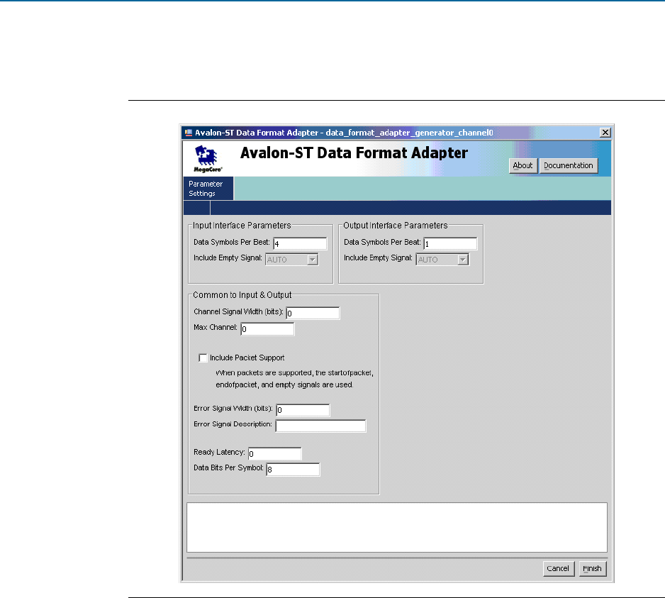
Figure 11–3 shows the wizard page that you use to set parameters for the Avalon-ST
Data Format Adapter.
Data Checker
The Avalon-ST Data Pattern Checker is provided as a Qsys component. It checks the
incoming data stream against standard test patterns, which include PRBS7, PRBS15,
PRBS23, PRBS31, High Frequency, and Low Frequency. It is used in conjunction with
the Avalon-ST Data Pattern Generator to test transceiver links.
The Avalon-ST Data Pattern Checker is available under Debug and Performance in
the Qsys component library tree. The checker is the core logic for data pattern
checking. Data patterns are accepted on 32-bit or 40-bit wide Avalon streaming sink
ports.
f For more information, refer to Avalon Streaming Data Pattern Generator and Checker
Cores chapter in the Embedded Peripherals User Guide.
Use the design examples as a starting point to work with a particular signal integrity
development board. You can also modify and customize the design examples to
match your intended transceiver design. When you use the Transceiver Toolkit, you
can check your transceiver link signal integrity without the completed final design.
Figure 11–3. Avalon-ST Data Format Adapter

11–8 Chapter 11: Transceiver Link Debugging Using the System Console
Transceiver Link Debugging Design Examples
Quartus II Handbook Version 11.1 November 2011 Altera Corporation
Volume 3: Verification
Use the design examples to quickly test the functionality of the receiver and
transmitter channels in your design without creating any custom designs with data
generators and checkers. You can quickly change the transceiver settings in the design
examples to see how they affect transceiver link performance. You can also use the
Transceiver Toolkit to isolate and verify the transceiver links without having to debug
other logic in your design.
Compiling Design Examples
Once you have downloaded the design examples, open the Quartus II software
version 10.0 or later and unarchive the project in the example. If you have access to the
same development board with the same device as mentioned in the readme.txt file of
the example, you can directly program your device with the provided programming
file in that example. If you want to recompile the design, you must make your
modifications to the configuration in Qsys, re-generate in Qsys, and recompile the
design in the Quartus II software to get a new programming file.
If you have the same board as mentioned in readme.txt file, but a different device on
your board, you must choose the appropriate device and recompile the design. For
example, some early development boards are shipped with engineering sample
devices.
If you have a different board, you must edit the necessary pin assignments and
recompile the design examples.
Changing Pin Assignments
You can edit pin assignments for various development kits. The following paragraphs
are examples of pin assignments for Stratix IV GX development kits.
f For further information about other development kits, read the readme.txt file which
comes with the design examples. For more information on the pinouts refer to their
respective user guide found on the All Development Kits page of the Altera website.
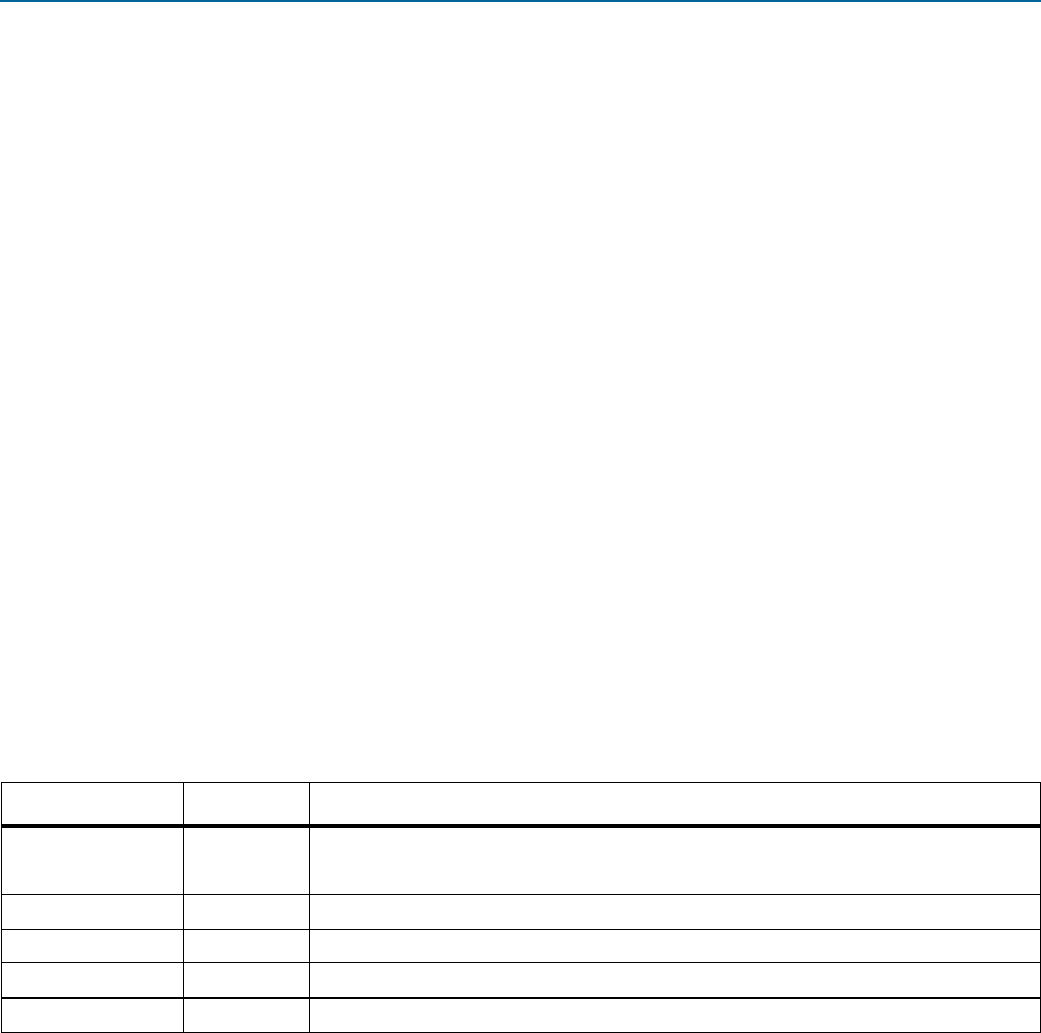
Table 11–1 shows the pin-assignment edits for the Stratix IV Transceiver Signal
Integrity Development Kit (DK-SI-4SGX230N). You must make these assignments
before you recompile your design.
Table 11–1. Stratix IV GX Top-Level Pin Assignments (DK-SI-4SGX230N)
Top-Level Signal Name I/O Standard
Pin Number on
DK-SI-4SGX230N Board
REFCLK_GXB2_156M25 (input) 2.5 V LVTTL/LVCMOS PIN_G38
S4GX_50M_CLK4P (input) 2.5 V LVTTL/LVCMOS PIN_AR22
GXB1_RX1 (input) 1.4-V PCML PIN_R38
GXB1_TX1 (output) 1.4-V PCML PIN_P36

Chapter 11: Transceiver Link Debugging Using the System Console 11–9
Transceiver Toolkit Link Test Setup
November 2011 Altera Corporation Quartus II Handbook Version 11.1
Volume 3: Verification
Table 11–2 shows the pin-assignment edits for the Stratix IV GX development kit
(DK-DEV-4SGX230N). You must make these assignments before you recompile your
design.
Similarly, you can change the pin assignment for your own board and recompile the
design examples.
Transceiver Toolkit Link Test Setup
To set up testing with the Transceiver Toolkit, perform the following steps:
1. Ensure the device board is turned on and is available before you start the System
Console or the Transceiver Toolkit. The connections are detected at startup of the
tool.
2. Program the device either with the programming file provided with the .zip file or
with the new programming file after you recompile your project.
3. Open the Transceiver Toolkit from the Tools menu in the Quartus II software.
4. Make sure the device is correctly programmed with the programming file in step 1
and that board settings, such as the jumper settings, are correct.
Loading the Project in System Console
From the Transceiver Toolkit, load the Quartus project file (*.qpf) by going to the File
menu and selecting Load Project. Whether you have recompiled the design or not, the
unzipped contents of the examples contain this file. After the project is loaded, you
can review the design information under System Explorer in the System Console.
Linking the Hardware Resource
Expand the devices tree in the System Explorer pane and find the device you are
using. Right click on a design and choose a device to link to. This is only necessary if
you do not use the usercode for automatic linking. If you are using more than one
Altera board, you can set up a test with multiple devices linked to the same design.
This is useful when you want to perform a link test between a transmitter and receiver
on two separate devices.
Table 11–2. Stratix IV GX Top-Level Pin Assignments (DK-DEV-4SGX230N)
Top-Level Signal Name I/O Standard
Pin Number on
DK-DEV-4SGX230N Board
REFCLK_GXB2_156M25 (input) LVDS PIN_AA2
S4GX_50M_CLK4P (input) 2.5 V LVTTL/LVCMOS PIN_AC34
GXB1_RX1 (input) 1.4-V PCML PIN_AU2
GXB1_TX1 (output) 1.4-V PCML PIN_AT4

11–10 Chapter 11: Transceiver Link Debugging Using the System Console
Transceiver Toolkit Link Test Setup
Quartus II Handbook Version 11.1 November 2011 Altera Corporation
Volume 3: Verification
1 For Transceiver Toolkit version 11.1 and later, to automatically instantiate and link
designs after they have been loaded in to the System Console, click Assignments on
the main menu of the Quartus II software, click Device on the Device and Pin
Options dialog box, and then turn on Auto usercode. When the project is loaded any
devices programmed with this project will automatically be linked. Prior to
Transceiver Toolkit version 11.1, you you must manually load your design as
described in the previous paragraphs.
To set up the transmitter channels, receiver channels, and transceiver links, go to the
Tools menu and select Transceiver Toolkit, or from the Welcome to the Transceiver
Toolkit tab, click on the Transceiver To o l k it to open the main Transceiver Toolkit
window. You can then create the channels, as described in the following section.
Creating the Channels
After you open the Transceiver Toolkit, there are three tabs in the System Console,
including Tr a ns m itt e r C h ann e ls , Receiver Channels, and Transceiver Links tabs.
The Transmitter Channel and Receiver Channel tabs are automatically populated
with the existing transmitter and receiver channels in the design, respectively.
However, you can create your own additional transmitter and receiver channels in a
situation where the expected configuration was not automatically populated. The
situation may occur if in the Link Channel tab you create a link between a transmitter
and receiver channel. Links define connectivity between a particular transmitter
channel and a receiver. The link forms the main logical unit that you test with the
Transceiver Toolkit.
Links are automatically created when a receiver channel and transmitter channel
share a transceiver channel. However, if you are not actually looping data back, but
using it to transmit or receive to another transceiver channel, you must define and
create a new link. For example, in Figure 11–4, a link is created in the Link Channel
tab between a transmitter and receiver channels of the same device.
Figure 11–4. Creating a Link Channel in Transceiver Toolkit

Chapter 11: Transceiver Link Debugging Using the System Console 11–11
Transceiver Toolkit Link Test Setup
November 2011 Altera Corporation Quartus II Handbook Version 11.1
Volume 3: Verification
You can also perform a physical link test without loopback by connecting one device
transmitter channel to another device receiver channel. In this channel you would
define that connection into a link, and tests would run off that link. For example, as
shown in Figure 11–2, use the transmitter and receiver channels of the same device
and loop them back on the far side of the board trace to check the signal integrity of
your high-speed interface on the board trace. You can select the link that you created
in the Transceiver Toolkit and use the different buttons to start and control link tests.
1 You can also communicate with other devices that have the capability to generate and
verify test patterns that Altera supports.
Running the Link Tests
Use the Link Channel tab options to control how you want to test the link. For
example, use the Auto Sweep feature to sweep various transceiver settings
parameters through a range of values to find the results that give the best BER value.
You can also open Transmitter, Receiver and Link Control panels to manually control
the PMA settings and run individual tests. You can change the various controls in the
panels to suit your requirements.
To perform an auto sweep link test, perform the following steps:
1. Select the link to test and click Auto Sweep to open the auto sweep panel for the
selected link.
2. Set the test pattern to test.
3. Select either Smart Auto Sweep or Full Auto Sweep. Full Auto Sweep runs a test
of every combination of settings that falls within the bounds that you set.
1 Smart Auto Sweep minimizes the number of tests run to reach a good setting, which
saves you time. Smart Auto Sweep does not test every possible setting, so may not
achieve the very best setting possible; however, it can quickly find an acceptable
setting.
4. Set up run lengths for each test iteration. The run length limits you set are ignored
when you run a smart sweep.
5. Set up the PMA sweep limits within the range you want to test.
6. Press Start and let the sweep run until complete.
After an Auto Sweep test has finished at least one iteration, you can create a report by
clicking Create Reports, which opens the Reports tab. The report shows data from all
tests that you have completed. You can sort by columns and filter data by regular
expression in the Reports tab. You can also export the reports to a .csv file by right
clicking on a report.
If you found a setting with the Smart Sweep mode, use the reported best case PMA
settings, and apply a +/- 1 setting to them, returning the test to Full Auto Sweep
mode. This helps you determine if the settings you chose are the best.
You can then choose your own runtime conditions, reset the Auto Sweep feature by
pressing Reset, and re-running the tests to generate BER data based on your own run
length conditions. This procedure allows you to obtain a good setting for PMA faster.
Review the BER column at the end of the full sweep to determine the best case.

11–12 Chapter 11: Transceiver Link Debugging Using the System Console
Transceiver Toolkit Link Test Setup
Quartus II Handbook Version 11.1 November 2011 Altera Corporation
Volume 3: Verification
1 When setting smart sweep ranges, try to include the 0 setting as often as possible, as
that setting often provides the best results.
Viewing Results in the EyeQ Feature
Advanced FPGA devices such as Stratix IV have built-in EyeQ circuitry, which is used
with the EyeQ feature in Transceiver Toolkit. The EyeQ feature allows you to estimate
the horizontal eye opening at the receiver of the transceiver. With this feature, you can
tune the PMA settings of your transceiver, which results in the best eye and BER at
high data rates.
Stratix V EyeQ circuitry adds the ability to see the vertical eye opening in addition to
the horizontal eye opening at the receiver of the transceiver. With this view of the eye,
you have a better idea of what is going on as you tune the PMA settings.
f For more information about the EyeQ feature, refer to AN 605: Using the On-Chip
Signal Quality Monitoring Circuitry (EyeQ) Feature in Stratix IV Transceivers.
To use the EyeQ feature in the Transceiver Toolkit to view the results of the link tests,
perform the following steps:
1. Select a Transceiver Link or Receiver Channel in the main Transceiver Toolkit
panel that you want to run EyeQ against.
2. Click Control Link or Control Channel to open control panels. Use these control
panels to set the PMA settings and test pattern that you want the EyeQ feature to
run against. You can check the report panel or Best Case column from an Auto
Sweep run for the settings with the best BER value and enter those PMA values
through the Transmitter and Receiver control panels.
3. Click EyeQ to open the EyeQ feature.
4. Review the test stop conditions and set them to your preference.
5. Choose a mode to run EyeQ.
■ Eye Contour–shows a BER contour graph of the eye. You can select a specific
target bit error rate that the Transceiver Toolkit uses asa means to try to find the
boundary. You can also select All, which allows the range of BER targets to be
simultaneously found and shown.
■ Bathtub–only finds the horizontal width of the eye. You can choose options for a
particular vertical step to sweep. You can also set the Transceiver Toolkit to sweep
all vertical steps and get an overlay of multiple slices through the eye.
When at least one run has completed, you can click Create Report to view details
of completed iterations of the sweep in a report panel.
6. Choose a horizontal and vertical interval, which allows you to skip steps to get a
faster though rougher view of the eye. If time is critical this can help speed up the
eye generation process, but results in less resolution as to the actual point of BER
crossover.

Chapter 11: Transceiver Link Debugging Using the System Console 11–13
Using Tcl in System Console
November 2011 Altera Corporation Quartus II Handbook Version 11.1
Volume 3: Verification
7. Click Run. The EyeQ Feature gathers the current settings of the channel and uses
those settings to start a sweep to create the eye. As the run is active you can view
the status through the progress bar. Depending on the mode you chose, you will
see a bathtub curve or eye contour. The width and height (if applicable) of the eye
is displayed once the run is completed. If the eye is un-centered or falls off the
edge and wraps around the other side, click Center Eye to center the data for
easier viewing.
8. You can change run options such as BER target, vertical phase step, or intervals,
and run again to collect more data. Switching between these options can show
previously run data so you can easily compare. If you click Create Report, all data
collected so far is shown in table format. If you change PMA settings, you must
click Reset to clear all data and take in the new PMA settings to be used for
testing. You can also click Reset to clear the data and collect a new set of data due
to changing conditions or circumstances.
If you want to change PMA settings and re-run the EyeQ feature, make sure you
first stop and reset the EyeQ feature. If you do not reset, the EyeQ feature
continues testing based on the original PMA settings of the current test and
overwrites any setting you may have changed through the control panel.
After you stop and reset the EyeQ feature, change settings in the link or receiver
channel control panel. Then click Start on the EyeQ feature to start a new set of
tests.
When you can see that you are running good PMA settings, the bathtub curve is wide,
with sharp slopes near the edges. The curve may be up to 30 units wide. If the bathtub
is narrow, maybe as small as two units wide, then the signal quality may be poor. The
wider the bathtub curve, the wider the eye you have. Conversely, the smaller the
bathtub curve, the smaller the eye.
h For more information about how to use the EyeQ feature, including the differences
between Stratix IV and Stratix V devices, refer to Working with the Transceiver Toolkit in
Quartus II Help.
Using Tcl in System Console
System Console is the framework in the Quartus II software that supports the
Transceiver Toolkit. System Console provides a number of Tcl commands that you can
use to build a custom test routine script to test the transceiver link using the data
generator and checker. System Console allows you to tune PMA parameter, such as
those for changing DC gain. To get help on the Tcl commands available, type
help
in
the Tcl console in System Console. To run a transceiver link test flow, perform the
following.You can perform all the tasks with Tcl commands in System Console.
1. Load the Quartus II project.
2. Find and link the design and service path.
3. Find and open links to transmitter channels and receiver channels.
4. Set up PRBS patterns to run on the link.
5. Set up PMA settings on transmitter and receiver channels.
6. Use PIO logic to generate a rising edge to enable the word aligner.

11–14 Chapter 11: Transceiver Link Debugging Using the System Console
Usage Scenarios
Quartus II Handbook Version 11.1 November 2011 Altera Corporation
Volume 3: Verification
7. Start the link test.
8. Poll the receiver for BER data.
9. When the test is finished, stop the link test.
10. Close the link.
f For more information about Tcl commands, refer to the Analyzing and Debugging
Designs with the System Console chapter in volume 3 of the Quartus II Handbook.
When you read the Tcl scripts provided with the design examples, they help you
understand how the Tcl commands are used.
Running Tcl Scripts
The tasks that you perform with the Transceiver Toolkit GUI for setting up your test
environment you can also save as Tcl scripts. For example, you can save the steps you
perform for loading your project in the Transceiver Toolkit by clicking Create Tcl
setup script on the File menu.
You can save your steps at various stages, such as when you add projects, create
design instances, link designs to devices, and create transceiver links. You can run
these scripts to reach the initial setup you created to get your specific configuration
ready for debugging. All the saved scripts are shown under the Scripts in the System
Explorer.You can execute a script by right-clicking on Scripts under the System
Explorer in the Transceiver Toolkit, and then clicking Run, or you can double-click on
the script. You can also execute scripts from the System Console command line.
Usage Scenarios
You can use the Transceiver Toolkit if you are debugging one device on one board or
more than one device on a single or multiple boards. Usually for a device you have a
single Quartus II design or project, but you can have one design targeted for two or
more similar devices on the same or different boards.
Possible scenarios for how you can use the Transceiver Toolkit in those situations
follow. The scenarios assume that you have programmed the device you are testing
with the relevant .sof.
■ “Linking One Design to One Device Connected By One USB Blaster Cable” on
page 11–15
■ “Linking Two Designs to Two Separate Devices on Same Board (JTAG Chained),
Connected By One USB Blaster Cable” on page 11–15
■ “Linking Two Designs to Two Separate Devices on Separate Boards, Connected to
Separate USB Blaster Cables” on page 11–15
■ “Linking Same Design on Two Separate Devices” on page 11–15
■ “Linking Unrelated Designs” on page 11–16
■ “Saving Your Setup As a Tcl Script” on page 11–16
■ “Verifying Channels Are Correct When Creating Link” on page 11–16
■ “Using the Recommended DFE Flow” on page 11–17

Chapter 11: Transceiver Link Debugging Using the System Console 11–15
Usage Scenarios
November 2011 Altera Corporation Quartus II Handbook Version 11.1
Volume 3: Verification
■ “Running Simultaneous Tests” on page 11–17
■ “Enabling Internal Serial Loopback” on page 11–18
h For further information on how to use the Transceiver Toolkit GUI to perform the
following scenarios, refer to Working with the Transceiver Toolkit in Quartus II Help.
Linking One Design to One Device Connected By One USB Blaster Cable
The following describes how to link one design to one device by one USB Blaster
cable.
1. Load the design for all the Quartus II project files you might need.
2. Link each device to an appropriate design (Quartus II project) if it has not
auto-linked.
3. Create the link between channels on the device to test.
Linking Two Designs to Two Separate Devices on Same Board (JTAG
Chained), Connected By One USB Blaster Cable
The following describes how to link two designs to two separate devices on the same
board, connected by one USB Blaster cable.
1. Load the design for all the Quartus II project files you might need.
2. Link each device to an appropriate design (Quartus II project) if it has not
auto-linked.
3. Open the project for the second device.
4. Link the second device on the JTAG chain to the second design (unless it
auto-links).
5. Create a link between the channels on the devices you want to test.
Linking Two Designs to Two Separate Devices on Separate Boards,
Connected to Separate USB Blaster Cables
The following describes how to link two designs to two separate devices on separate
boards, connected to separate USB Blaster cables.
1. Load the design for all the Quartus II project files you might need.
2. Link each device to an appropriate design (Quartus II project) if it has not
auto-linked.
3. Create the link between channels on the device to test.
4. Link the device you connected to the second USB Blaster cable to the second
design.
5. Create a link between the channels on the devices you want to test.
Linking Same Design on Two Separate Devices
The following describes how to link the same design on two separate devices.

11–16 Chapter 11: Transceiver Link Debugging Using the System Console
Usage Scenarios
Quartus II Handbook Version 11.1 November 2011 Altera Corporation
Volume 3: Verification
1. In the Transceiver Toolkit, open the Quartus II project file (.qpf) you are using on
both devices.
2. Link the first device to this design instance. Follow the same linking method that
you used on previous steps.
3. Link the second device to the design. Follow the same linking method that you
used on previous steps.
4. Create a link between the channels on the devices you want to test.
Linking Unrelated Designs
Use a combination of the above steps to load multiple Quartus II projects and make
links between different systems. You can perform tests on completely separate
systems that are not related to one another. All tests run through the same tool
instance.
1 Do not attempt to start multiple instances of the Transceiver Toolkit. You can only
control multiple devices and run multiple tests simultaneously through the same
instance of the Transceiver Toolkit.
Saving Your Setup As a Tcl Script
After you open projects and define links for the system so that the entire physical
system is correctly described, use the command Save Tcl Script to create a setup
script.
Close and reopen the Transceiver Toolkit.
Open the scripts folder in System Explorer and double-click the script to reload the
system. You can also right-click and choose Run Script, or use the menu command
Load Script to run the appropriate script.
Verifying Channels Are Correct When Creating Link
After you load your design and link your hardware, you should verify that the
channels you have created are correct and looped back properly on the hardware. You
should be able to send the data patterns and receive them correctly.
Perform the following steps before you perform Auto Sweep or EyeQ tests to verify
your link and correct channel, which may save time in the work flow.
1. Assuming that you have completed the system setup, choose the transmitter
channel, and click Control Transmitter Channel.
2. Set the test pattern to prbs 7.
3. Start the pattern generator, press Start.
4. Navigate to the control panel, choose the receiver channel, and click Control
Receiver Channel.
5. Set the test pattern to prbs 7.
6. Press Start.

Chapter 11: Transceiver Link Debugging Using the System Console 11–17
Usage Scenarios
November 2011 Altera Corporation Quartus II Handbook Version 11.1
Volume 3: Verification
7. Verify channels that the channels are correct, based on the following conditions:
a. If the Run status is good (green), the receiver is receiving data. To verify that
the data is coming from the expected transmitter, you can navigate to the
transmitter and do either of the following:
■ Click Stop on the transmitter and see if Data Locked on the receiver turns
off.
■ If the receiver shows 0 error bits, click Inject Error on the transmitter and
see if that error shows up on the receiver.
b. If the Run status is bad (yellow with flashing exclamation point), do either of
the following:
■ The data quality is too poor to lock. You can manually adjust the PMA
settings to see if you can get a lock. If not, use the Auto Sweep tool if you
are certain the channel is correct.
■ The receiver and transmitter are not connected together. You either picked
the wrong pair, or you have not made the physical connection between the
pair.
After you have verified that the transmitter and receiver are talking to each other,
create a link in the link tab with these two transceivers so that you can perform Auto
Sweep and EyeQ tests with this pair.
Using the Recommended DFE Flow
To use the DFE flow recommended by Altera, perform the following steps:
1. Use the Auto Sweep flow to find optimal PMA settings while leaving the DFE
setting OFF.
2. Take the best PMA setting achieved, if BER = 0. Then you do not have to do
anything if you use this setting.
3. If BER > 0, then use this PMA setting and set minimum and maximum values in
the Auto Sweep tool to match this setting. Set the DFE MAX range to limits for
each of the three DFE settings.
4. Run the Auto Sweep tool to determine which DFE setting results in the best BER.
Use these settings in conjunction with the PMA settings for the best results.
Running Simultaneous Tests
To run link tests simultaneously in one instance of the Transceiver Toolkit, perform
the following steps:
1. Set up your system correctly with one of the previous set-up scenarios.
2. In the control panel for the link you work on, run either the Auto Sweep or EyeQ
tool.
3. After you start the test, return to the Transceiver Toolkit control panel.
4. Select the control panel tab.
5. Open the Tools menu and click Transceiver Toolkit, which returns you to the
control panel.

11–18 Chapter 11: Transceiver Link Debugging Using the System Console
Quick Guide to Using the Transceiver Toolkit in the Quartus II Software
Quartus II Handbook Version 11.1 November 2011 Altera Corporation
Volume 3: Verification
6. Repeat step 2 until all tests are run.
7. The control panel shows which links and channel resources are in use to help
identify which channels already have tests started and their current run status.
Enabling Internal Serial Loopback
You can use the Transceiver Toolkit GUI control for serial loopback. In the Transceiver
Toolkit version 11.1 and later to enable the serial loopback, check the box Serial
Loopback. To enable the serial loopback in Tcl, use the System Console commands.
h For more information, refer to Working with the Transceiver Toolkit in Quartus II Help.
Quick Guide to Using the Transceiver Toolkit in the Quartus II Software
This section provides a quick guide for using the Transceiver Toolkit, and includes the
following:
■ “Preparing to Use the Transceiver Toolkit” on page 11–18
■ “Working with Design Examples” on page 11–19
■ “Modifying Design Examples” on page 11–20
■ “Setting a Link in the Transceiver Toolkit for High-Speed Link Tests” on
page 11–21
■ “Running Auto Sweep Tests” on page 11–22
■ “Running EyeQ Tests” on page 11–22
■ “Running Manual Tests” on page 11–23
■ “Using a Typical Flow” on page 11–23
■ “Following the Online Demonstration” on page 11–24
f For more information about how to use the Transceiver Toolkit, refer to the Altera
Training page of the Altera website.
Preparing to Use the Transceiver Toolkit
Following is a list of recommended prerequisites to get you prepared for using the
Transceiver Toolkit:
■ You should know how to use the Quartus II software.
f For further information on how to use the Quartus software, refer to the
Introduction to Quartus II Software.
■ Become familiar with an overview description of the Transceiver Toolkit as
described in “Transceiver Toolkit Overview” on page 11–1.
■ Design examples you may download from the Altera website were created using
Qsys software, such that you should have knowledge of Qsys. Prior to Qsys,
design examples were created with SOPC Builder. Knowledge of SOPC Builder
will help with your understanding of Qsys.

Chapter 11: Transceiver Link Debugging Using the System Console 11–19
Quick Guide to Using the Transceiver Toolkit in the Quartus II Software
November 2011 Altera Corporation Quartus II Handbook Version 11.1
Volume 3: Verification
■ You need some experience working with Altera high-speed transceiver devices,
especially Stratix IV GX and Stratix V devices.
■ Working with the Transceiver Toolkit GUI is described in further detail in the
Quartus II Help.
h For more information, refer to Working with the Transceiver Toolkit in Quartus
II Help.
■ You can find further reference materials, including Quartus II design examples, on
the Altera website.
Working with Design Examples
You can download design examples from the Altera website, as described in
“Transceiver Link Debugging Design Examples” on page 11–3. These design
examples help you get started quickly using the Transceiver Toolkit without having to
make your own designs to perform high-speed link tests.
The design example is a Qsys designed system using various components. The
components include JTAG to Avalon Master Bridge, Custom PHY IP core, Low
Latency PHY IP core, and data generator and checkers with their own data format
and adapters. These components can be found in a Qsys library.
The Qsys system is wrapped in a top-level HDL file in Verilog.
The online design examples are targeted for device-specific signal integrity boards.
You can use these design examples with other boards by changing assignments.
The first design example is a one-channel design with an 8-bit interface and a
Custom PHY IP core data rate of 1.25 mbps. This example contains one JTAG to
Avalon Master Bridge, one Custom PHY IP core, one data generator, one data checker,
and timing and data format adapters for each checker and generator.
The second design example is a four-channel bonded design with a 10-bit interface
and a Custom PHY IP core data rate of 2.5 gbps.
1 Some device families have a different set of examples than this four-channel bonded
design.
The design contains one JTAG to Avalon master, one Custom PHY IP core, four data
generators and data checkers, and timing and data format adapters for each checker
and generator.
To use these examples, perform the following:
1. Download the examples from the Altera website.
f Download the Transceiver Toolkit design examples from the On-Chip
Debugging Design Examples page of the Altera website.
2. Unzip the examples files.
3. You can directly program the device with the design provided, or you can modify
the design.

11–20 Chapter 11: Transceiver Link Debugging Using the System Console
Quick Guide to Using the Transceiver Toolkit in the Quartus II Software
Quartus II Handbook Version 11.1 November 2011 Altera Corporation
Volume 3: Verification
4. If you modify the design you must then recompile the program to get a new
programming file. Use the new programming file to program your device.
5. Open the Transceiver Toolkit from the Tools menu of the Quartus II software. You
do not need to create links because a default set is automatically created for you.
h For more information, refer to Transceiver Toolkit Window in Quartus II Help.
6. You can change settings for the links manually or you can use the Transceiver
Auto Sweep panel.
7. Run the Auto Sweep and EyeQ tests from the Transceiver Toolkit window to find
the optimal settings.
h For more information about running Auto Sweep and EyeQ tests and the
difference between Stratix IV GX and Stratix V testing, refer to Working with
the Transceiver Toolkit in Quartus II Help.
Modifying Design Examples
You may want to modify the design examples to change the data rate of the Custom
PHY IP core, add more channels to the Custom PHY IP core, or change the device.
Online training on the Altera website provides further detailed descriptions of how to
modify the design examples.
f For more information about the online training, refer to “Following the Online
Demonstration” on page 11–24.
To modify the design examples that you download from the Altera website, open the
existing project in the Qsys tools in the Quartus II software. Qsys has a graphical
interface that is shown in the online training, so that following the instructions is
straightforward.
You can make changes to the design examples so that you can use a different
development board or different device. You make pin assignment changes and then
recompile the design, as shown in the online training.
You either create a new programming file with the Programmer in the Quartus II
software, or use the existing programming file that comes with the zipped design
examples. The Programmer must complete its programming function 100% with no
errors.
f When you recompile the design a new programming file is created. If you do not
change the design you can use the included programming file.
h For more information about programming a device, refer to Programming Devices in
Quartus II Help.

Chapter 11: Transceiver Link Debugging Using the System Console 11–21
Quick Guide to Using the Transceiver Toolkit in the Quartus II Software
November 2011 Altera Corporation Quartus II Handbook Version 11.1
Volume 3: Verification
Setting a Link in the Transceiver Toolkit for High-Speed Link Tests
1. Make sure your development board is properly configured.
a. You must make the proper connections for the links you want to test.
b. Your board must be up and running, and programmed with the correct
programming file.
c. Set-up examples are shown in the online training.
f Refer to the Transceiver Toolkit Online Demo on the Altera website.
2. Open the Transceiver Toolkit from the Tools menu in the Quartus II software, if the
panel is not already showing on the screen.
3. The System Explorer panel on the left side of the System Console shows design
connections, loaded designs, and design instances. Ensure that your hardware is
shown in the System Explorer.
4. Load your design project, which is a .qpf file, into the System Console with the
Load Design command.
5. Open the Transceiver Toolkit from the Tools menu in the System Console. You can
now view all the design information.
6. Link the hardware you want to test to the Quartus II project. Right-click on a
device and select Link device to. Then select the Quartus II project name from the
list.
1 In most cases links are automatically loaded, so you may not need to link
hardware as described in step 6 if you are working with design examples.
1 To automatically instantiate and link designs after they have been loaded in
to the System Console, click Assignments on the main menu of the Quartus
II software, click Device on the Device and Pin Options dialog box, and
then turn on Auto usercode.
7. You can save all actions you perform into a Tcl script. On the File menu of the
System Console, click Create Tcl setup script. This action creates a Tcl script of
your current setup, including receivers, transmitters, and links you created. The
next time you start the Transceiver Toolkit, you can double-click the script to open
the setup you saved.
8. All the scripts are listed under Scripts in the System Explorer pane. You can add
any Tcl script when you place the script into your Scripts folder. You can then
right-click the Scripts folder to open the folder and add or modify files.
9. On the Transceiver Toolkit main window, the Transceiver Links tab is
automatically populated with the channel information in your design.
10. By default links are created between the transceiver and receiver of the same
channel and are shown in the Transceiver Links tab.
11. You can also create an additional link between a different transceiver and receiver
channel.

11–22 Chapter 11: Transceiver Link Debugging Using the System Console
Quick Guide to Using the Transceiver Toolkit in the Quartus II Software
Quartus II Handbook Version 11.1 November 2011 Altera Corporation
Volume 3: Verification
12. On the Transceiver Links tab, you click Control Link, Auto Sweep, or EyeQ to run
tests.
13. On the Receiver Channels tab, you click Control Channel, Auto Sweep, or EyeQ
to control and run tests.
Running Auto Sweep Tests
To use Auto Sweep in the Transceiver Toolkit to perform high-speed link tests
perform the following:
1. On the Transceiver Links tab, click Auto Sweep to open the Auto Sweep panel.
You use this panel to perform Auto Sweep Bit Error Rate (BER) testing.
2. Previous transceiver settings are shown in the Auto Sweep tab. You can select
different combinations of settings here before starting a test. Different settings
change the case count.
3. When you start the Auto Sweep test the Current column displays the current test
results. The Best column displays the best results so far obtained during the test.
4. You create reports by clicking Create Report once Auto Sweep is completed or
while the testing is in process. You can export all settings and results to reports in a
.csv format. Columns in the reports show various transceiver settings and you can
sort the columns, which simplifies finding the best test cases. For example, when
you sort on the BER column, it gives you the settings that produce the lowest BER.
h For more information about running Auto Sweep tests and the difference
between Stratix IV GX and Stratix V testing, refer to Working with the
Transceiver Toolkit in Quartus II Help.
Running EyeQ Tests
To use the EyeQ feature in the Transceiver Toolkit, perform the following:
1. On the Transceiver Links tab, click EyeQ to open the EyeQ panel. This panel
shows the transceiver settings. To change settings you open either the Transceiver
Links or Receiver Links control panels, make setting changes, and run the EyeQ
test again. These panels open when you click either Control Links or Control
Channel on the Transceiver Links tab or the Transceiver Channels tab.
2. Use EyeQ to verify receiver settings. EyeQ can see how receiver settings affect eye
width.
3. Click Reset when you change settings and want to run the EyeQ test again.
4. When the EyeQ test begins and the first sweep is completed, the bathtub curve is
generated and displays. If you do not see a bathtub curve at the end of the test run,
but see a hill instead, click Center Eye to position the bathtub curve in the middle
of the pane.
5. Click Create Report to generate EyeQ reports. If you sort the report by BER
column, the number of rows that have a BER value of 0 are considered the unit of
width of the eye from the specified PMA settings.

Chapter 11: Transceiver Link Debugging Using the System Console 11–23
Quick Guide to Using the Transceiver Toolkit in the Quartus II Software
November 2011 Altera Corporation Quartus II Handbook Version 11.1
Volume 3: Verification
h For more information about running Auto Sweep tests and the difference
between Stratix IV GX and Stratix V testing, refer to Working with the
Transceiver Toolkit in Quartus II Help.
Running Manual Tests
Besides performing Auto Sweep and EyeQ tests with the Transceiver Toolkit, you can
also perform manual tests and change PMA settings while testing is in progress as
follows:
1. Ensure that Auto Sweep tools have finished, and both Auto Sweep and EyeQ
windows are closed.
2. Click Control Link on the Transceiver Links tab. The Receiver, Transmitter, and
Link Control panels open.
3. Select a test pattern and begin testing.
4. While the test is running you can change the PMA settings on the Transmitter or
Receiver Control panels.
5. Press Inject Error on the Transmitter Control panel and view results on the
Receiver Control panel. You can only use Inject Error to verify that have
connected the proper transmitter to your receiver.
6. Click Reset on the Receiver Control panel after changing the PMA settings so that
the BER counter starts from the beginning.
Using a Typical Flow
You can use the tools in the Transceiver Toolkit however you choose. Following is a
typical flow:
1. Perform an Auto Sweep test to get the best BER with various combinations of
PMA settings. You can also check the Best Case column in an Auto Sweep BER
report for the settings with the best BER value. You then enter those PMA values
in the Transmitter Channel and Receiver Channel control tabs.
2. Use the control panels to set the PMA settings and test pattern that you want to
run the EyeQ test against. Select a Transceiver Link or Receiver Channel in the
Transceiver Toolkit tab that you want to run the EyeQ test against. Click Control
Link or Control Channel to open the control panels.
3. Re-run EyeQ sweeps with different settings to see if the eye width changes. When
you see that you are running good PMA settings, the bathtub curve is wide and
has sharp slopes near the edges. The curve may be up to 30 units wide. If the
bathtub curve is narrow, say two units wide for example, then the signal quality
may be poor. The wider the bathtub curve, the wider the eye you have.
1 Do not change any control panel settings while you are actively using Auto
Sweep tools. If you do manually use the control panel, make sure all
receivers and transmitters are stopped before attempting to use an Auto
Sweep tool.
11–24 Chapter 11: Transceiver Link Debugging Using the System Console
Conclusion
Quartus II Handbook Version 11.1 November 2011 Altera Corporation
Volume 3: Verification
Following the Online Demonstration
f For an online demonstration of how to use the Transceiver Toolkit to run a high-speed
link test with one of the design examples, refer to the Transceiver Toolkit Online Demo
on the Altera website.
The demonstration shows how to perform link testing with one device. The
Transceiver Toolkit is scalable for other purposes, such as performing board-to-board
testing, testing device-to-device on the same development board, and testing internal
loopbacking of the same channel with no external loopbacking required.
Conclusion
You gain productivity when optimizing high-speed transceiver links in your board
designs with the Transceiver Toolkit and design examples provided from Altera. You
can easily set up automatic testing of your transceiver channels so that you can
monitor, debug, and optimize transceiver link channels in your board design. You
then know the optimal PMA settings to use for each channel in your final FPGA
design. You can download standard design examples from Altera’s website, and then
customize the examples to use in your own design.
Document Revision History
Table 11–3 lists the revision history for this handbook chapter.
f For previous versions of the Quartus II Handbook, refer to the Quartus II Handbook
Archive.
f Take an online survey to provide feedback about this handbook chapter.
Table 11–3. Document Revision History
Date Version Changes
November, 2011 11.1.0
Maintenance release. This chapter adds new Transceiver Toolkit features.
Minor editorial updates.
May, 2011 11.0.0 Added new Tcl scenario.
December 2010 10.1.0 Changed to new document template. Added new 10.1 release features.
August 2010 10.0.1 Corrected links
July 2010 10.0.0 Initial release
