
Adams 2021.0.2
Getting Started: Adams Car
Worldwide Web
www.mscsoftware.com
Support
http://www.mscsoftware.com/Contents/Services/Technical-Support/Contact-Technical-Support.aspx
Disclaimer
This documentation, as well as the software described in it, is furnished under license and may be used only in accordance with the
terms of such license.
MSC Software Corporation reserves the right to make changes in specifications and other information contained in this document
without prior notice.
The concepts, methods, and examples presented in this text are for illustrative and educational purposes only, and are not intended
to be exhaustive or to apply to any particular engineering problem or design. MSC Software Corporation assumes no liability or
responsibility to any person or company for direct or indirect damages resulting from the use of any information contained herein.
User Documentation: Copyright © 2021 MSC Software Corporation. Printed in U.S.A. All Rights Reserved.
This notice shall be marked on any reproduction of this documentation, in whole or in part. Any reproduction or distribution of this
document, in whole or in part, without the prior written consent of MSC Software Corporation is prohibited.
This software may contain certain third-party software that is protected by copyright and licensed from MSC Software suppliers.
Additional terms and conditions and/or notices may apply for certain third party software. Such additional third party software terms
and conditions and/or notices may be set forth in documentation and/or at
http://www.mscsoftware.com/thirdpartysoftware (or successor
website designated by MSC from time to time). Portions of this software are owned by Siemens Product Lifecycle Management, Inc.
© Copyright 2021
The MSC Software logo, MSC, MSC Adams, MD Adams, and Adams are trademarks or registered trademarks of MSC Software
Corporation in the United States and/or other countries. Hexagon and the Hexagon logo are trademarks or registered trademarks of
Hexagon AB and/or its subsidiaries. FLEXlm and FlexNet Publisher are trademarks or registered trademarks of Flexera Software.
Parasolid is a registered trademark of Siemens Product Lifecycle Management, Inc. All other trademarks are the property of their
respective owners.
ADAM:V2021.0.2:Z:Z:Z:DC-GS-CAR
Corporate Europe, Middle East, Africa
MSC Software Corporation MSC Software GmbH
4675 MacArthur Court, Suite 900 Am Moosfeld 13
Newport Beach, CA 92660 81829 Munich, Germany
Telephone: (714) 540-8900 Telephone: (49) 89 431 98 70
Toll Free Number: 1 855 672 7638 Email: [email protected]
Email: ameri[email protected]
Japan Asia-Pacific
MSC Software Japan Ltd. MSC Software (S) Pte. Ltd.
KANDA SQUARE 16F 100 Beach Road
2-2-1 Kanda Nishikicho, Chiyoda-ku #16-05 Shaw Tower
Tokyo 101-0054, Japan Singapore 189702
Telephone: (81)(3) 6275 0870 Telephone: 65-6272-0082
Email: MSCJ.Marke[email protected] Email: [email protected]

Documentation Feedback
At MSC Software, we strive to produce the highest quality documentation and welcome your feedback.
If you have comments or suggestions about our documentation, write to us at:
documentation-
.
Please include the following information with your feedback:
Document name
Release/Version number
Chapter/Section name
Topic title (for Online Help)
Brief description of the content (for example, incomplete/incorrect information, grammatical
errors, information that requires clarification or more details and so on).
Your suggestions for correcting/improving documentation
You may also provide your feedback about MSC Software documentation by taking a short 5-minute
survey at:
http://msc-documentation.questionpro.com.
Note: The above mentioned e-mail address is only for providing documentation specific
feedback. If you have any technical problems, issues, or queries, please contact
Technical
Support
.
Getting Started Using Adams Car

Getting Started Using Adams Car
Overview
14
Introducing Adams Car
Overview
This chapter introduces you to Adams Car. It contains the following sections:
Starting Adams Car Standard Interface
Starting Adams Car Template Builder
Switching Between Interface Modes
Familiarizing Yourself with Adams Car
Plotting Results
Starting Adams Car Standard Interface
In this section, you learn how to start Adams Car Standard Interface in the Windows and the Linux
environments.
In the Windows environment, you start Adams Car from the Start button. In the Linux environment, you
start Adams Car from the Adams Toolbar. For more information, see the online help for Running and
Configuring Adams.
To start Adams Car on Windows:
1. From the Start menu, point to Programs, point to Adams x (where x is release number), and then
select Adams Car.
The Welcome dialog box appears on top of the Adams Car main window.
2. Do one of the following:
• If the Welcome dialog box contains the options Standard Interface and Template Builder, select
Standard Interface, and then select OK.
• If the Welcome dialog box does not contain any options, then Adams Car is already configured
to run in standard mode. Select OK.
The Adams Car Standard Interface window appears as shown below. Familiarize yourself with the
Adams Car window and read the tips in Familiarizing Yourself with Adams Car.

15
Introducing Adams Car
Starting Adams Car Standard Interface
Figure 1 Adams Car Standard Interface
To start Adams Car on Linux:
1. At the command prompt, enter the command to start the Adams Toolbar, and then press Enter. The
standard command that MSC Software provides is
adamsx, where x is the version number, for
example 2021_0_2
The Adams Toolbar appears.

Getting Started Using Adams Car
Starting Adams Car Template Builder
16
2. Click the Adams Car icon
The Welcome dialog box appears on top of the Adams Car main window.
3. Do one of the following:
• If the Welcome dialog box contains the options Standard Interface and Template Builder, select
Standard Interface, and then select OK.
• If the Welcome dialog box does not contain any options, then Adams Car is already configured
to run in standard mode. Select OK.
The Adams Car Standard Interface window appears as shown above. Familiarize yourself with the
Adams Car window and read the tips in Familiarizing Yourself with Adams Car.
Starting Adams Car Template Builder
Before you start Adams Car Template Builder, make sure that your private configuration file, .acar.cfg,
shows that you can work in expert-user mode. Your private configuration file is located in your home
directory.
To check the user mode:
1. In a text editor, such as jot or notepad, open .acar.cfg.
2. Verify that the following line appears as shown:
ENVIRONMENT MDI_ACAR_USERMODE expert
This line sets the user mode for the Adams Car session.
To start Adams Car Template Builder on Windows:
1. From the Start menu, point to Programs, point to Adams x (where x is the release number), and then
select Adams Car.
The Welcome dialog box appears on top of the Adams Car main window.
2. Select Template Builder.
3. Select OK.
The Adams Car Template Builder window appears as shown in the figure below. Familiarize yourself
with the Adams Car window and read the tips in Familiarizing Yourself with Adams Car.

17
Introducing Adams Car
Starting Adams Car Template Builder
Figure 2 Adams Car Template Builder

Getting Started Using Adams Car
Switching Between Interface Modes
18
To start Adams Car Template Builder on Linux:
1. At the command prompt, enter the command to start the Adams Toolbar, and then press Enter. The
standard command that MSC Software provides is
adamsx, where x is the version number, for
example
adams2021_0_2.
The Adams Toolbar appears.
2. Click the Adams Car icon .
The Welcome dialog box appears on top of the Adams Car main window.
3. Select Template Builder.
4. Select OK.
The Adams Car Template Builder window appears as shown in the figure above. Familiarize yourself
with the Adams Car window and read the tips in Familiarizing Yourself with Adams Car.
Switching Between Interface Modes
Once you have started Adams Car in the Standard Interface or Template Builder modes, you can easily switch
between them.
To switch between modes:
In Standard Interface: From the Tools menu, select Adams Car Template Builder.
In Template Builder: From the Tools menu, select Adams Car Standard Interface.
Familiarizing Yourself with Adams Car
Take a few minutes to familiarize yourself with the Adams Car main window.
The following tips help you quickly become familiar with Adams Car:
You use the menus along the top of the window to execute commands and display dialog boxes.
Notice that some menus are shaded in grey. This indicates that you cannot execute these commands
because you do not have a subsystem open. When you open a subsystem, these menus change to
black indicating that you can execute the commands.
You can use the main shortcut menu to execute simple commands, such as rotating views, zooming,
and fitting assemblies in the main window. To display the main shortcut menu, right-click in the
main window, away from any entities.
Instead of manually entering text in boxes that require database objects, you can have Adams Car
automatically do this task for you. To do this, right-click the text box of interest, and then select an
option. For example, if you were modifying a hardpoint, Adams Car would present you with the
following options:
• Point to Hardpoint (or the entity of interest) and then select Pick. On the main window, place
the cursor on top of the hardpoint. When the name of the hardpoint appears, you can click the
left mouse button to select that hardpoint.

19
Introducing Adams Car
Plotting Results
• Point to Hardpoint, and then select Guesses. From the pop-up menu that appears, select the
entity name you want to use.
• Point to Hardpoint, and then select Browse. Adams Car displays the Database Navigator, which
contains a list of entities, hardpoints in this case. Double-click the entity name you want to use.
Plotting Results
When you’re ready to review the results of your analyses, you can display the post-processing tool and view
the results of the simulations you performed.
To plot results:
1. While in Adams Car Standard Interface, from the Review menu, select Postprocessing Window or
press F8.
Adams Car launches Adams PostProcessor, a post-processing tool that lets you view the results of
simulations you performed. For more information about Adams PostProcessor, see the Adams
PostProcessor online help.
2. To return to Adams Car, select the Return to Modeling Environment tool or press F8.

Getting Started Using Adams Car
Plotting Results
20

13
Introducing the Driving Machine
Overview
Introducing the Driving Machine
Overview
This tutorial introduces you to the Driving Machine and the associated Event Builder. It contains the
following sections:
About the Driving Machine
About the Event Builder
About the Driving Machine
You can use Adams Car to study full-vehicle behavior for many different aspects of vehicle development, such
as handling, ride, and durability.
Adams Car offer several standard full-vehicle analyses (ramp steer, straight line braking, and so on) allowing
engineers and analysts to quickly characterize certain vehicle attributes. In addition to standard full-vehicle
analyses, the Driving Machine supports an XML event file that lets you create your own custom full-vehicle
analyses. These analyses are typically built from a number of mini-maneuvers, which when simulated in
succession, define a meaningful vehicle test. An example of such a test could be a braking-in-turn analysis,
which would consist of the following mini-maneuvers:
1. Drive along a road in a straight line, maintaining a constant velocity. When a constant velocity has
been achieved for a specified amount of time and within a prescribed tolerance, end the first mini-
maneuver.
2. Start the second mini-maneuver by steering the vehicle onto a prescribed radius and maintaining the
same velocity. When the velocity has stabilized for a set amount of time and within a prescribed
tolerance, end the second mini-maneuver.
3. Start the third mini-maneuver by maintaining the previous radius and velocity from the second mini-
maneuver. After a two-second delay, apply the brake to achieve a desired longitudinal deceleration
while maintaining the radius from the second mini-maneuver by controlling the steering wheel.
For a human driver, this is quite a simple task: you simply drive in a straight line, turn the steering wheel, and
then apply the brake. In the Adams Car environment, you have more control over the driving event. Such an
analysis requires a reasonably complex event file.
Looking at the mini-maneuvers described above, the control attributes for each mini-maneuver are.
Steering wheel has to keep the vehicle straight. Throttle has to maintain vehicle speed. Gear, clutch,
and brake are not used.
Steering wheel has to steer the vehicle, then control the radius of turn. Throttle has to maintain
vehicle speed. Gear, clutch, and brake are not used.
Steering wheel has to maintain the radius of turn (steering motion will change during braking based
on the understeer/oversteer characteristics of the vehicle). Brake has to be applied and controlled to
achieve the desired lateral acceleration. Throttle has to be lifted. Application of the clutch will need
to be considered also.

Getting Started Using Adams Car
About the Event Builder
14
The Driving Machine permits a fine level of control over the full-vehicle model. This control has historically
been exercised by using a .
dcf file, which is based on the TeimOrbit data file standard. The Driving Machine
now uses XML event files to describe mini-maneuvers. You can still access .
dcf files, however, Driving
Machine automatically converts them to XML event file format.
About the Event Builder
The Event Builder lets you create and modify XML event files. The information in a new full-vehicle analysis
is then saved in an .
xml-based file, which can be used in the driving control file full-vehicle analysis.
The Event Builder consists of two distinct interfaces:
The mini-maneuver creation interface - Used to quickly create the mini-maneuvers; there is no limit
to the number of mini-maneuvers that can be created.
The mini-maneuver editor - Used to specify the Driving Machine parameters for each separate mini-
maneuver. In the example maneuver specified earlier, you would first create three mini-maneuvers,
then fill in the details for each mini-maneuver (steering, throttle, clutch, gear, brake, and end
conditions). In this tutorial, you will go through this process.

13
Using the Event Builder
Overview
Using the Event Builder
Overview
In this chapter, you will learn the basics of creating multiple mini-maneuvers, establishing the appropriate
application areas for those mini-maneuvers, and setting end conditions for each mini-maneuver.
The chapter contains the following sections:
Creating an Event
Creating the Three Mini-Maneuvers
Defining the Mini-Maneuver Parameters
Running the New Analysis
Creating an Event
Before you can create an event, you must create a new file, as explained next.
To display the Event Builder:
1. Open the assembly MDI_Demo_Vehicle.asy.
2. From the Simulate menu, point to Full-Vehicle Analysis, and then select Event Builder.
Adams Car displays the Event Builder, which is grayed out because you do not have a .
xml file yet.
To create a new file:
1. From the Event Builder’s File menu, select New.
The New File dialog box appears.
2. Enter the name of the event: braking_in_a_turn. This is the name of the file that will be saved to your
hard drive or network drive with a .
xml extension.
3. Select OK.
Your Adams product creates the file and also defines the first mini-maneuver,
MINI_1.
Entering Set-up and Global Parameters
The top of the Event Builder window, as shown next, has three fields and two tabs that provide global
parameters and set initial conditions.

Getting Started Using Adams Car
Creating the Three Mini-Maneuvers
14
The Event File text box shows the file name you specified when you created or opened the file, and the
path, for new files, is the working directory. You can’t change the file name or path in the Event Builder. You
can use the Speed and
Gear text boxes to enter an initial speed and gear, respectively, for the vehicle prior to
starting the first mini-maneuver.
The
Static Set-up tab lets you complete the definition of the vehicle state prior to beginning of the first
mini-maneuver. The
Gear Shifting Parameters tab lets you define global parameters related to gear
shifting. The Event Builder outputs this information so that the Driving Machine uses these parameters for
any shifting required by any mini-maneuver.
For this exercise, the default Gear Shifting Parameters should be adequate, so you won’t change them. Because
the first mini-maneuver that you specify is going to be a straight line, you will use the straight static setup.
For a description of the static setup methods available in the Driving Machine, see
Structure of Event Files in the
Adams Car online help.
1. In the
Static Set-up tab, change set Task to straight. Note that the rest of the parameters are not
used because they will be overwritten by the initial values computed during the quasi-static setup.
You must set the initial velocity of the vehicle. The value of the initial velocity depends on the units
in which you are using the Event Builder.
2. To check the units or make a change, from the Settings menu, select Units.
By default, the length unit is set to meters and the time unit is set to seconds. Therefore, the velocity
must be set in meters/second.
3. To verify that velocity units are in meters/second, click in the Speed text box at the top of the Event
Builder, and then read what is displayed in the Current Field Unit text box at the bottom of the Event
Builder.
4. To set the target vehicle velocity, in the Speed text box, enter 27.7 (as previously explained, units are
meters/second), which corresponds to approximately 100 km/h.
5. To set the initial gear, in the Gear text box, enter 5.
Creating the Three Mini-Maneuvers
To complete the braking-in-turn event, you must create three mini-maneuvers.

15
Using the Event Builder
Defining the Mini-Maneuver Parameters
To create the mini-maneuvers:
1. To go to the mini-maneuver table editor, select .
The mini-maneuver table editor appears. Note that by default, the first mini-maneuver,
MINI_1, is
already defined.
2. To create one more mini-maneuver, in the Name text box at the bottom of the Event Builder
window, enter MINI_2, and then select Add.
3. To create the last mini-maneuver, in the Name text box, enter MINI_3, and then select Add.
The mini-maneuver window appears as follows:
4. In the Abort Time for MINI_2, change the abort time to 5.
5. To save the event file with the 3 mini-maneuvers, select Save.
Your Adams product saves the file,
braking_in_a_turn.xml, in your current working directory.
Defining the Mini-Maneuver Parameters
Now that you defined the three mini-maneuvers, you must define what each of the application areas and end
conditions will do during the mini-maneuvers.
The application areas are steering, throttle, brake, clutch, and gear. For each application area, you define the
Driving Machine control method (open, machine, or SmartDriver).
End conditions define a vehicle state that the Driving Machine uses to terminate a mini-maneuver. End
conditions are extremely flexible, and let you define many types of situations that cause the vehicle state to
move on to the next mini-maneuver. The following are some example end conditions:
End conditions can have a single condition, such as time is greater than 5 seconds.
End conditions can have a single value that must be within a tolerance over a prescribed period of
time. Lateral acceleration is 0.5 g over a two-second period and within a 0.05 g tolerance.
Multiple end conditions, such as time is greater than 5 seconds or vehicle velocity is lower than
10 kph.
Combined end condition, such as vehicle velocity equal 100 kph (within a tolerance) and
longitudinal acceleration equals 0 g (within a tolerance). Event Builder lets you group end
conditions, allowing you to specify multiple conditions required to terminate a maneuver.
For more information on end conditions, see
Specifying Conditions in the Adams Car online help.

Getting Started Using Adams Car
Defining the Mini-Maneuver Parameters
16
To define mini-maneuver parameters for MINI_1:
1. To access the mini-maneuver property editor, double-click the name of the mini-maneuver you want
to edit. In this case, MINI_1.
2. For the first mini-maneuver, the vehicle should drive in a straight line and maintain constant velocity.
To achieve this, set the following parameters:
• Steering tab
Actuator Type: rotation
Control Method: machine
Steer Control: straight
The Steer Control setting enables the Driving Machine to drive the vehicle in a straight line.
• Throttle tab
Control Method: machine
Speed Control: maintain
Velocity: 27.7
The Velocity setting enables the Driving Machine to maintain the steady-state velocity that you
established earlier. The Driving Machine will control the throttle to maintain this velocity much
like a cruise control system.
• Braking tab
Control Method: machine
The Throttle and Brake settings control the longitudinal velocity of the vehicle.
• Gear tab
Control Method: open
Control Type: constant
Control Value: 5
Maintain the same gear specified for the static setup.
• Clutch tab
Control Method: open
Control Type: constant
Control Value: 0.0
For the first mini-maneuver, you’re using the Driving Machine for the steering and the throttle,
so you can maintain the vehicle speed during straight-line driving.
The purpose of the first mini-maneuver is to reach a dynamic steady-state end condition.
Although not absolutely necessary for this type of event, it helps demonstrate some important
aspects of the Driving Machine. To satisfy a steady-state condition, the vehicle must be traveling
a straight line (very low lateral acceleration) at a stable velocity (very low longitudinal velocity).
You can use end conditions to group these two conditions together to satisfy the steady-state
requirements.

17
Using the Event Builder
Defining the Mini-Maneuver Parameters
To create end conditions for MINI_1:
1. Select the Conditions tab.
2. Select .
3. In the Name text box, enter END_2.
4. Select Add.
5. Modify the end conditions as follows:
• END_1
Type: lon_accel
Test : ==
Trigger Value: 0.0
Error: 0.05
Filter Time: 2.0
Delay Time:0.0
Group Name: MINI_1
• END_2
Type: lat_accel
Test : ==
Trigger Value: 0.0
Error: 0.05
Filter Time: 2.0
Delay Time: 0.0
Group Name: MINI_1
Note that you used
MINI_1 for both group names. Because END_1 and END_2 have the same
Group Name, the vehicle state must satisfy both end conditions for the maneuver switch to occur.
6. Select Save.
To define mini-maneuver parameters for MINI_2:
1. Select to the left of Name label for the text box containing MINI_1.
2. Double-click on the name of the mini-maneuver, MINI_2.
3. Set the mini-maneuver parameters as follows:
• Steering tab
Actuator: rotation
Control Method: machine

Getting Started Using Adams Car
Defining the Mini-Maneuver Parameters
18
Steer Control: skidpad
Entry Distance: 20.0
Radius: 120
Turn Direction: Right
These parameters will start the vehicle turning at the beginning of the second mini-maneuver.
• Throttle tab
Control Method: machine
Speed Control: maintain
Velocity: 27.7
These parameters allow the Driving Machine to maintain the straight line velocity established in
MINI_1. The steering parameters established in the steering block are not modified.
• Braking tab
Control Method: machine
• Gear tab
Control Method: open
Control Type: constant
Control Value: 5
Maintain the same gear specified for the static setup.
• Clutch tab
Control Method: open
Control Type: constant
Control Value: 0.0
For the second mini-maneuver, you’re tellling the Driving Machine to make a right turn and
control the vehicle on a radius of 120 m.
Next, you will create two end conditions to verify that the vehicle has reached a steady-state
cornering condition.
To create end conditions for MINI_2:
1. Select the Conditions tab.
2. In the Name text box, enter END_1.
3. Select Add.
4. Create the second end condition, END_2, just as you created the first.
5. Modify the end conditions as follows:
• END_1
Condition Type: lon_accel

19
Using the Event Builder
Defining the Mini-Maneuver Parameters
Test Type: ==
Trigger Value: 0.0
Error: 0.05
Filter Time: 2.0
Delay Time: 0.0
Group Name: MINI_2
• END_2
Condition Type: curvature
Test Type: ==
Trigger Value: 0.00833
Error: 0.00005
Filter Time: 2.0
Delay Time: 0.0
Group Name: MINI_2
These end conditions ensure that a radius of approximately 120 m is followed at a velocity of 100
kph.
6. Select Save.
To define mini-maneuver parameters for MINI_3:
1. Select .
2. Double-click on the name of the mini-maneuver, MINI_3.
3. Set the mini-maneuver parameters as follows:
• Steering tab
Actuator: rotation
Control Method: machine
Steer Control: skidpad
Entry Distance: 0.0
Radius: 120
Turn Direction: Right
These parameters maintain the radius from the previous mini-maneuver.
• Throttle tab
Control Method:machine
• Braking tab
Control Method: machine

Getting Started Using Adams Car
Defining the Mini-Maneuver Parameters
20
Speed Control: lon_accel
Start Time: 1.0
Long. Acc.: - 3.0
These parameters drop the throttle at the beginning of the third mini-maneuver to zero, and
control the deceleration to 3.0 m/s
2.
• Gear tab
Control Method: machine
The Driving Machine controls the gear selection.
• Clutch tab
Control Method: machine
The Driving Machine controls the clutch selection.
For the third mini-maneuver, you use the Driving Machine for all vehicle activity; you want the
Driving Machine to maintain the vehicle radius while at the same time braking the vehicle at 3
m/s
2
. You use a single end condition for the third mini-maneuver, which is velocity. You trigger
the end of the simulation if the velocity is below 10 kph which is approximately 2.77 m/s.
To create the end condition for MINI_3:
1. Select the Conditions tab.
2. In the Name text box, enter END_1.
3. Select Add.
4. Modify the end condition as follows:
• END_1
Condition Type: velocity
Test Type: <<
Trigger Value: 2.77
Error:0.01
Filter Time: 0.0
Delay Time: 0.0
5. Select Save. You can then select Cancel to close the Event Builder window.
By default, your Adams product saves the file in the current working directory. If you are not sure
where the current working directory is located, do following:
• In Adams Car, from the File menu, select Select Directory.
This displays a dialog that shows the current working directory.

21
Using the Event Builder
Running the New Analysis
Running the New Analysis
To run the new analysis:
1. Do one of the following, depending on your Adams product.
In Adams Car:
• From the Simulate menu, point to Full-Vehicle Analysis, and then select File Driven Events.
• Double-click the Driver Control Files text box to display a file selection dialog box that already
points to your working directory. Then, double-click the name of the new event file you created
in this tutorial (braking_in_a_turn.xml).
• In the Output Prefix text box, enter Event_Build.
• Leave the other parameters set to their defaults. For help on filling out this dialog box, press F1.
• Select OK to run the analysis.
You are now ready to use the Event Builder to run full-vehicle analyses.

Getting Started Using Adams Car
Running the New Analysis
22

31
Suspension Analysis Tutorial
What You Will Create and Analyze
Suspension Analysis Tutorial
This tutorial teaches you how to modify and analyze a double-wishbone suspension.
This chapter includes the following sections:
What You Will Create and Analyze
Setting Up the Suspension and Steering Subsystems
Performing a Baseline Parallel Wheel Travel Analysis
Performing a Baseline Pull Analysis
Modifying the Suspension and Steering Subsystem
Performing an Analysis on the Modified Assembly
Comparing the Analysis Results
Finishing Up
This tutorial takes about one hour to complete.
What You Will Create and Analyze
During this tutorial, you analyze and modify an assembly of a front suspension and steering subsystem. To
perform the analysis, you must first create a double-wishbone suspension and steering subsystem from
standard Adams Car templates and subsystems. Adams Car templates define a subsystem’s topology and
specify how one subsystem connects to another. Templates also contain default parameters, such as locations,
part masses, and inertias.
The figure shows the suspension and steering assembly (in shaded mode) that you will analyze and modify.

Getting Started Using Adams Car
Setting Up the Suspension and Steering Subsystems
32
Figure 1 Suspension and Steering Assembly
After you create the suspension and steering assembly, you perform two types of analyses to understand its
kinematics:
A baseline parallel wheel travel analysis that moves the assembly vertically through the suspension’s
rebound-bump travel.
A baseline pull analysis to measure the brake pull at the steering wheel.
Once you understand the kinematics of the assembly, you modify the suspension subsystem’s geometry to
decrease the scrub radius, which should reduce the pull on the steering wheel. You confirm the reduction by
analyzing the modified assembly again, using the same type of analysis and comparing the new results to the
results yielded by the previous analysis.
Setting Up the Suspension and Steering Subsystems
In this section, you work with a suspension and steering assembly from two subsystems: a suspension
subsystem and a steering subsystem. You create the suspension subsystem using the standard double-
wishbone template. You don’t need to create the steering subsystem. Instead, you can open an existing
subsystem that we’ve provided.
After creating and opening the subsystems, you create an assembly that contains the subsystems and a test rig.

33
Suspension Analysis Tutorial
Setting Up the Suspension and Steering Subsystems
Creating a New Front Suspension Subsystem
You create the front suspension subsystem based on a double-wishbone design stored in the standard template
named
_double_wishbone.tpl, and then save it.
After you create the subsystem, you save it in an Adams Car database. When you save a subsystem, Adams
Car stores it in the database designated as the default writable database. Initially, the private database is the
default writable database, but as you become more familiar with Adams Car, you can change your writable
database. Later, when you are sure the design is complete or ready for review, you can have your database
administrator save the file in a shared database or allow others to access it from your private database.
To create the front suspension subsystem:
1. Start Adams Car Standard Interface as described in Starting Adams Car Standard Interface.
2. From the File menu, point to New, and then select Subsystem.
The New Subsystem dialog box appears.
3. In the Subsystem Name text box, enter UAN_FRT_SUSP.
4. Set Minor Role to front. A minor role defines the subsystem’s function and its placement in the
assembly (for example, front or rear). In this case, you select front because you are creating a front
suspension.
5. Right-click the Template Name text box, point to Search, and then select shared_car_database.
The Select File dialog box appears.
6. Select templates.tbl and double-click _double_wishbone.tpl.
The Template Name text box now contains the file
_double_wishbone.tpl and an alias to its
directory path.
7. Verify that Translate from default position is not selected.
8. Select the Comment tool .
The Entity Comment dialog box appears.
9. In the Comment Text text box, enter Baseline UAN Front Suspension.
10. Select OK.
11. Select OK again.
Adams Car creates the suspension subsystem using the default data contained in the template and
displays it as shown next:
Tip: For information on any dialog box, press F1 when the dialog box is active.

Getting Started Using Adams Car
Setting Up the Suspension and Steering Subsystems
34
Figure 2 Suspension Subsystem
To save the suspension subsystem:
From the File menu, select Save.
Adams Car saves the subsystem in your default writable database, which might be your private
database. For more information on databases, see the Adams Car online help.
Creating a Suspension Assembly
In this section, you create a new suspension assembly and add to it a steering subsystem.
To create the suspension assembly:
1. From the File menu, point to New, and then select Suspension Assembly.
The New Suspension Assembly dialog box appears.

35
Suspension Analysis Tutorial
Performing a Baseline Parallel Wheel Travel Analysis
2. In the Assembly Name text box, enter my_assembly.
3. Click the folder icon next to Suspension Subsystem.
The name of the suspension subsystem you just created appears.
4. Select Steering Subsystem.
5. Right-click the Steering Subsystem text box, point to Search, and then select the
shared_car_database.
The Select File dialog box appears.
6. Select subsystems.tbl and double-click MDI_FRONT_STEERING.sub.
The Steering Subsystem text box now contains
MDI_FRONT_STEERING.sub and an alias to its
directory path.
Note that by default Adams Car selects a test rig for the assembly,
__MDI_SUSPENSION_TESTRIG.
7. Select OK.
The Message Window appears, informing you of the steps Adams Car takes when creating the
assembly.
Adams Car displays the suspension and steering assembly in the main window.
8. Select Close, to close the Message Window.
Performing a Baseline Parallel Wheel Travel Analysis
You now perform a parallel wheel travel analysis on the suspension and steering assembly, and then plot and
view the results, as explained in the following sections:
Defining Vehicle Parameters
Performing the Analysis
Animating the Results
Plotting the Results
Defining Vehicle Parameters
Before performing a suspension analysis, you must specify several parameters about the vehicle in which you
intend to use the suspension and steering subsystems. These parameters include the vehicle’s wheel base and
sprung mass, whether or not the suspension is front- or rear-wheel drive, and the braking ratio. For this
analysis, you enter the parameters to indicate front-wheel drive and a brake ratio of 64% front and 36% rear.
To define vehicle parameters:
1. From the Simulate menu, point to Suspension Analysis, and then select Set Suspension Parameters.
The Suspension Analysis: Setup Parameters dialog box appears. It contains default settings to help you
quickly set up a suspension analysis.
2. Set up the analysis as follows:
• Suspension Assembly: my_assembly

Getting Started Using Adams Car
Performing a Baseline Parallel Wheel Travel Analysis
36
• Tire Model: User Defined
• Tire Unloaded Radius: 300
• Tire Stiffness: 200
• Wheel Mass: 10.0
• Sprung Mass: 1400
• CG Height: 300
• Wheelbase: 2765
• Drive Ratio: 100
All driving force is applied to the front wheels.
• Brake Ratio: 64
The brake ratio value indicates the % of braking force that is applied to the front brakes.
3. Select OK.
Performing the Analysis
Now that you’ve defined the vehicle parameters, you can run the parallel wheel travel analysis. During the
analysis, the test rig applies forces or displacements, or both, to the assembly, as defined in a loadcase file. For
this analysis, Adams Car generates a temporary loadcase file based on the inputs you specify.
This parallel wheel travel analysis moves the wheel centers from -100 mm to +100 mm relative to their input
position, while holding the steering fixed. During the wheel motion, Adams Car calculates many suspension
characteristics, such as camber and toe angle, wheel rate, and roll center height.
To perform the analysis:
1. From the Simulate menu, point to Suspension Analysis, and then select Parallel Wheel Travel.
2. Set up the analysis as follows:
• Suspension Assembly: my_assembly
• Output Prefix: baseline
• Number of Steps: 15
• Mode of Simulation: interactive
• Bump Travel: 100
• Rebound Travel: -100
• Travel Relative To: Wheel Center
• Steering Input: Angle
3. Select the Comment tool .
4. In the Comment Text text box, enter Baseline Parallel Wheel Travel Analysis.
5. Select OK.

37
Suspension Analysis Tutorial
Performing a Baseline Parallel Wheel Travel Analysis
6. Select OK again.
The Message Window appears, informing you of the steps Adams Car takes when performing the
analysis. Adams Car analyzes the suspension and steering assembly and applies to it the displacements
and loads defined in the submission dialog box.
7. When the analysis is complete, select Close.
Animating the Results
In this section, you view the analysis you just ran. Adams Car has already loaded the animation and graphic
files for you.
To animate the results:
1. From the Review menu, select Animation Controls.
2. Select the Play tool .
Adams Car animates the motion of the suspension analysis. Notice that the suspension moves from
rebound (down), to bump (up), and that the steering wheel does not rotate.
3. When the animation is complete, close the dialog box.
Plotting the Results
In this section, you create several plots from the parallel wheel travel analysis results. In a plot configuration
file, we have provided all the information that Adams Car needs to create the plots. The plot configuration
file not only specifies which plots Adams Car should create, but also how the plots should look, including
their horizontal and vertical units, and colors. Storing plotting information in a plot configuration file lets
you quickly regenerate plots after each analysis.
To plot the results:
1. Press F8 Key or Launch Adams PostProcessor as explained in Plotting Results.
2. From the Plot menu, select Create Plots.
3. Enter the following specifications:
• Plot Configuration File:
mdids://shared_car_database/plot_configs.tbl/mdi_suspension_short.plt
• Plot Title: Baseline Parallel Travel Analysis - UAN_FRT_SUSP
4. Select OK.
Adams Car creates the plots. To cycle through the plots, from the Main toolbar, use the Previous
Pages and Next Pages tools .
5. View the plot named
Scrub Radius, shown next. Scrub radius is the distance from the point at the
intersection of the steering axis (also known as the kingpin axis) and the ground plane, to the line of
intersection of the wheel and ground planes.

Getting Started Using Adams Car
Performing a Baseline Parallel Wheel Travel Analysis
38
Plot of Scrub Radius versus Wheel Travel
Notice that the scrub radius varies little with wheel travel and is approximately 34 mm. A positive
scrub radius means the steering axis lies inboard of the center of the tire contact patch.
From the analysis you’ve completed, you have enough information to calculate the approximate
torques produced about the steering axes using the difference in left to right braking forces and the
34 mm scrub radius.
In addition, using the results of that calculation and the steering geometry, you can calculate the
resulting unbalanced force at the steering rack and the pull (torque) needed at the steering wheel to
keep the wheels straight.
In the next sections, you use Adams Car to perform these calculations.
Deleting Plots
To prepare for the baseline pull analysis, delete the plots you created in the previous sections.

39
Suspension Analysis Tutorial
Performing a Baseline Pull Analysis
To delete plots:
1. In the treeview, hold down the left mouse button, and then drag the cursor across the names of the
plots you want to delete.
2. From the Edit menu, select Delete.
3. From the File menu, select Close Plot Window or press F8.
Adams Car returns to the main window.
Performing a Baseline Pull Analysis
You can now perform a baseline pull analysis to study the pull on the steering wheel. You will use the results
of this pull analysis as the baseline against which you compare the results of another pull analysis that you
perform after you modify the location of the steering axis. By comparing the results from the two analyses,
you can determine if the modifications were successful.
Performing a baseline pull analysis involves the following:
Defining a Loadcase File
Performing the Analysis
Animating the Results
Plotting the Results
Saving the Plot Configuration
Defining a Loadcase File
Before you can run the baseline pull analysis, you need to create a loadcase file to drive the analysis. In the
loadcase file, you specify the unequal braking forces to simulate braking on a split-μ surface and the
beginning, or upper, and ending, or lower, steering wheel angles.
To calculate the unequal brake forces, we assume that the vehicle is braking at a rate of 0.5 g’s deceleration,
with a 64% front and 36% rear brake ratio, a vehicle mass of 1,400 kg, and the front braking force split 55%
left and 45% right. Based on these assumptions, the total front braking force is:
1,400 kg * 0.5 g’s * 9. 81 m/s
2
/g * 0.64 = 4,395 N
From this, the left and right braking forces are:
Left braking force = 0.55 * 4,395 N or 2,417 N
Right braking force = 4,395 N - 2,417 N or 1,978 N
You can use these calculations to define the loadcase file.

Getting Started Using Adams Car
Performing a Baseline Pull Analysis
40
To define a loadcase file:
1. From the Simulate menu, point to Suspension Analysis, and then select Create Loadcase.
2. Fill in the dialog box as shown next, and then select OK.
Note: If Select Loadcase Type is not set to Static Load, your dialog box will look slightly
different. Make sure you select Static Load first, and then proceed to fill in the dialog
box.

41
Suspension Analysis Tutorial
Performing a Baseline Pull Analysis
Adams Car creates the loadcase file, named brake_pull.lcf, and stores it in your private database.
It stores the loadcase file as text (ASCII) and you can print it or edit it manually.
To create the loadcase file, Adams Car takes the parameters that you entered and generates a table of
input values. For the parameters that you entered, Adams Car generates a table that varies steering
wheel angle from -180 to 180 in 15 steps, while holding the braking forces constant.

Getting Started Using Adams Car
Performing a Baseline Pull Analysis
42
Table 1 shows the loadcase file values
:
Performing the Analysis
You can now use the loadcase file that you just created to perform an analysis that determines the pull
characteristics of the suspension and steering assembly.
To perform the pull analysis:
1. From the Simulate menu, point to Suspension Analysis, and then select External Files.
2. Set up the analysis as follows:
• Suspension Assembly: my_assembly
• Output Prefix: baseline
• Mode of Simulation: interactive
• Loadcase Files: mdids://private/loadcases.tbl/brake_pull.lcf
3. Make sure Load Analysis Results is selected.
4. Select OK.
Table 1 Loadcase file values
Steering Wheel: Left Brake Force: Right Brake Force:
-180 2417 1978
-156 2417 1978
-132 2417 1978
-108 2417 1978
-84 2417 1978
-60 2417 1978
-36 2417 1978
-12 2417 1978
12 2417 1978
36 2417 1978
60 2417 1978
84 2417 1978
108 2417 1978
132 2417 1978
156 2417 1978
180 2417 1978

43
Suspension Analysis Tutorial
Performing a Baseline Pull Analysis
Animating the Results
In this section, you view an animation of the analysis Adams Car just performed.
To animate the results:
1. From the Review menu, select Animation Controls.
2. Select the Play tool.
Adams Car animates the turning motion of the steering subsystem. You should see the wheels turn as
the steering wheel rotates. The wheel centers should not move vertically.
3. Close the Animation Controls dialog box.
Plotting the Results
You can now use the results from the baseline pull analysis to create two plots, as explained in the following
sections:
Plotting Steering Wheel Torque versus Steering Wheel Angle
Plotting Scrub Radius versus Steering Wheel Angle
Plotting Steering Wheel Torque versus Steering Wheel Angle
You now create a plot of the steering wheel torque versus the steering wheel angle.
To set up the plot:
1. Press F8 or Launch Adams PostProcessor just as you did before.
2. From the treeview, double-click page_1.
3. Select plot_1.
4. In the property editor, clear the selection of Auto Title and Auto Subtitle.
5. In the Title text box, enter Brake Pull Analysis.
6. In the Subtitle text box, enter Steering Wheel Torque vs Steering Wheel Angle.
7. Right-click the treeview area, point to Type Filter, point to Plotting, and then select Axes.
8. From the treeview, double-click plot_1, and then select haxis.
9. In the property editor, select the Labels tab.
10. In the Label text box, enter Steering Wheel Angle [degrees].
11. From the treeview, select vaxis.
12. In the Label text box, Steering Wheel Torque [Nmm].
To create the plot:
1. Verify that Source is set to Requests.
Adams Car automatically displays data information.

Getting Started Using Adams Car
Performing a Baseline Pull Analysis
44
2. From the Simulation list, select baseline_brake_pull.
3. From the right of the dashboard, set Independent Axis to Data.
The Independent Axis Browser appears. You perform the next four steps in the browser.
4. From the Filter list, select user defined.
5. From the Request list, select steering_displacements. You might have to scroll down to see this entry.
6. From the Component list, select angle_front.
7. Select OK.
8. From the Filter list, select user defined.
9. From the Request list, expand test rig in the Request list, and then select steering_wheel_input.
10. From the Component list, select steering_wheel_input_torque.
11. Select Add Curves.
Adams Car takes the data requested and automatically generates the curve on the current plot
template, as shown next:
Figure 3 Plot of Steering Wheel Torque versus Steering Wheel Angle
The plot shows the torque that the test rig applies to the steering wheel to hold the wheel in position.
The torque is negative, meaning that the test rig applies a clockwise torque to counteract the unequal
braking force that pulls the wheel counterclockwise, as if making a left turn.

45
Suspension Analysis Tutorial
Performing a Baseline Pull Analysis
Plotting Scrub Radius versus Steering Wheel Angle
In this section, you create a plot of the scrub radius versus the steering wheel angle. After you create the plot,
you can modify it to change the number of divisions in the vertical and horizontal axes so they cover a larger
range and define the minimum and maximum limits to be displayed in the vertical axis.
To set up the plot:
1. From the Main toolbar, select the New Page tool .
2. In the treeview, double-click page_2.
3. Select plot_2.
4. Make sure that Auto Title and Auto Subtitle are not selected.
5. In the Title text box, enter Brake Pull Analysis.
6. In the Subtitle text box, enter Scrub Radius vs Steering Angle.
7. Right-click the treeview area, point to Type Filter, point to Plotting, and then select Axes.
8. Double-click plot_2 to expand it so the names of the axes are visible.
9. From the treeview, select haxis.
10. In the property editor, select Labels.
11. In the Label text box, enter Steering Wheel Angle [degrees].
12. From the treeview, select vaxis.
13. In the Label text box, enter Scrub Radius [mm].
To create the plot:
1. Verify that Source is set to Requests.
2. From the Simulation list, select baseline_brake_pull.
3. From the Filter list, select user defined.
4. From the Request list, expand test rig in the Request list, and then select scrub_radius.
5. From the Component list, select left.
This defines the vertical axis component.
6. Select Add Curves.
Adams Car takes the data requested and generates the curve on the current plot template, as shown
next:

Getting Started Using Adams Car
Performing a Baseline Pull Analysis
46
Figure 4 Plot of Scrub Radius versus Steering Angle
Notice that the scrub radius appears to vary a lot with respect to the steering angle because of the
vertical plot scale, when in fact it only varies 0.21 mm over the total range of steering wheel angle. To
show that this variation is small, you must modify the vertical axis so it covers a larger range of values.
To modify the plot:
1. Select the vertical axis.
2. From the property editor, select the Format tab.
3. Clear the selection of Auto Scale.
4. In the Limits text boxes, enter 0 and 100.
A modified plot appears as shown next.

47
Suspension Analysis Tutorial
Modifying the Suspension and Steering Subsystem
Figure 5 Modified Plot of Scrub Radius versus Steering Wheel Angle
Notice that the variation in scrub radius with respect to the steering wheel angle now appears smaller.
Saving the Plot Configuration
Saving the changes that you made to the plots in a plot configuration file lets you easily recreate the plots later
in this tutorial, after you modify the suspension and steering assembly.
To save the plot configuration:
1. From the File menu, point to Export, and then select Plot Configuration File.
2. In the Configuration File Name text box, enter brake_pull.
3. Make sure All Plots is selected.
4. Select OK.
5. From the File menu, select Close Plot Window or press F8.
Adams Car returns to the main window.
Modifying the Suspension and Steering Subsystem
For a double-wishbone suspension, the line running from the lower spherical joint to the upper spherical joint
defines the steering axis or kingpin axis. If these joints move outboard while the rest of the suspension
geometry remains unchanged, the scrub radius is decreased.
In the suspension subsystem that you created, two hardpoint pairs define the locations of these joints:

Getting Started Using Adams Car
Modifying the Suspension and Steering Subsystem
48
hpl_lca_outer and hpr_lca_outer, where lca_outer means lower control arm outer, and
the prefix
hpl means hardpoint left and the prefix hpr means hardpoint right.
hpl_uca_outer and hpr_uca_outer, where uca_outer means upper control arm outer and the prefix
hpl means hardpoint left and the prefix hpr means hardpoint right.
Hardpoints define independent locations in space.
To decrease the scrub radius, you modify the locations that these hardpoints define, as explained in the
following sections:
Modifying Hardpoint Locations
Saving the Modified Subsystem
Modifying Hardpoint Locations
You must first display a table that contains data about the current locations that the hardpoints define. You
can then modify the hardpoint locations. You only need to indicate how you want to move the left hardpoints
in each pair, and Adams Car modifies the right hardpoints accordingly.
To view hardpoint locations:
1. From the View menu, select Subsystem.
The Display Subsystem dialog box appears, already containing the subsystem
my_assembly.UAN_FRT_SUSP.
2. Select OK.
3. From the Adjust menu, point to Hardpoint, and then select Table.
The Hardpoint Modification Table appears. It displays the locations of all the hardpoints in the
assembly. You can use this table to display and modify the locations of any of the hardpoints.
The locations of the paired hardpoints differ only by the sign of the Y location. Therefore, the paired
hardpoints are symmetrical about the X-Z plane. With symmetrical hardpoints, you only need to
move one of the hardpoints, not both. If you want, however, you can break the symmetry and move
only one of the hardpoints of a symmetrical pair.
To see the symmetry, select left or right from the bottom of the Hardpoint Modification Table.
To modify the hardpoints:
1. Click the cell common to hpl_lca_outer and loc_y.
2. Change the existing value to -775. This moves the hardpoint point 25 mm outboard.
3. Scroll the table window down until you see the hardpoint hpl_uca_outer.
4. Click the cell common to hpl_uca_outer and loc_y.
5. Change the existing value to -700. This moves the hardpoint 25 mm outboard.
6. Select Apply.
Adams Car changes the hardpoint locations of the two hardpoints and their symmetrical right pairs.

49
Suspension Analysis Tutorial
Performing an Analysis on the Modified Assembly
7. Close the dialog box.
Saving the Modified Subsystem
In this section, you save the subsystem you just modified.
To save the subsystem:
1. From the File menu, select Save.
Before saving the file, Adams Car asks you if you want to create a backup copy of the file.
2. Select No. This overwrites the subsystem file in your default writable database.
Adams Car saves the subsystem file that you created.
Performing an Analysis on the Modified Assembly
To determine how the modifications to the suspension subsystem changed the pull on the steering wheel, you
perform a pull analysis on the modified suspension and steering assembly. You can use the same loadcase file
that you created in Defining a Loadcase File.
To perform the analysis:
1. From the Simulate menu, point to Suspension Analysis, and then select External Files.
The dialog box displays the appropriate loadcase file.
2. In the Output Prefix text box, enter modified.
3. Select the Comment tool.
4. In the Comment Text text box, enter Steering axis moved 25mm outboard.
5. Select OK.
6. Select OK again.
Adams Car analyzes the modified suspension and steering assembly.
Comparing the Analysis Results
You now create a plot that compares the analysis results from the baseline suspension and steering assembly
with the analysis results from the modified suspension and steering assembly.
To compare the analysis results:
1. Press F8 to launch Adams PostProcessor.
2. From the Plot menu, select Create Plots.
3. In the Plot Configuration File text box, enter mdids://private/plot_configs.tbl/brake_pull.plt.
4. In the Plot Title text box, enter Brake Pull Analysis - UAN_FRT_SUSP.

Getting Started Using Adams Car
Comparing the Analysis Results
50
5. To plot the results of the two analyses on one page, select Cross Plotting.
6. Select OK.
7. Use the plot navigation tools to cycle through the plots.
8. Focus on the plot of the Steering Wheel Torque vs Steering Wheel Angle, shown in the following
figure. It contains values for both the baseline and the modified suspension and steering assembly.
Notice that the pull is reduced for all steering wheel angles, as expected.
Figure 6 Comparison Plot for Steering Wheel Torque vs Steering Wheel Angle
9. Cycle through the plots until you see a plot of the Scrub Radius vs Steering Wheel Angle, shown
below. This plot also contains values for both the baseline and the modified suspension and steering
assembly. Notice that the scrub radius decreased from 34 mm to about 9 mm because of the
suspension modifications.

51
Suspension Analysis Tutorial
Finishing Up
Figure 7 Comparison Plot for Scrub Radius versus Steering Wheel Angle
Finishing Up
Before you continue with the full-vehicle tutorial in the next chapter, you should clean up your directory by
deleting the plots and simulations, and closing the subsystems that you created and modified.
Deleting Simulations
Closing Assemblies
Deleting Simulations
You first delete the simulations for the baseline and modified analyses and then you return to the Adams Car
main window.
To delete simulations:
1. Right-click the treeview, point to Type Filter, point to Modeling, and then select Analyses.
2. To show the current simulations, double-click my_assembly.
The treeview updates and displays the current simulations.
3. Select the simulations you want to delete.
4. From the Edit menu, select Delete.
Adams Car deletes the simulations.
5. From the File menu, select Close Plot Window.
Adams Car returns to the main window.

Getting Started Using Adams Car
Finishing Up
52
Closing Assemblies
You can now close the suspension and steering assembly.
To close the assembly:
1. From the File menu, point to Close, and then select Assembly.
The Close Assembly dialog box appears. By default it contains the name of your assembly.
2. Select OK.

55
Flexible Bodies Tutorial
Overview
Flexible Bodies Tutorial
Overview
In this tutorial, you run analyses on suspension and full-vehicle assemblies to see the effects of flexible bodies.
Before you work through this tutorial, make sure you have:
Adams Flex.
Completed the tutorial we’ve provided with Adams Flex in the guide, Getting Started Using Adams
Flex.
A moderate level of finite element modeling proficiency.
This chapter includes the following sections:
About Modal Flexibility in Adams Car
What You Will Create and Analyze
Working with Flexible Bodies in Suspension Assemblies
Working with Flexible Bodies in Full-Vehicle Assemblies
This tutorial takes about one hour to complete.
About Modal Flexibility in Adams Car
Adams Car integrates and fully supports the Adams Flex plug-in. Adams Flex allows you to build flexible
bodies into your templates using a modes method, called modal flexibility. It assigns a set of mode shapes (or
eigenvectors) to a flexible body. The flexible body modeling element designates a system state variable to each
eigenvector and calculates the relative amplitude during a time analysis. The principle of linear superposition
is then used to combine the mode shapes at each time step to reproduce the total deformation of the flexible
body.
The following sections further explain flexible bodies:
About Integrating Flexible Bodies
About Flexible Body Damping Ratio
About Integrating Flexible Bodies
Integrating flexible bodies into templates or subsystems lets you capture inertial and compliance effects
during handling and comfort simulations, study deformations of your flexible components, and predict loads
with greater accuracy, therefore achieving more realistic results. Once the flexible body is created, Adams Car
displays its geometric representation in the main window.
The flexible body characteristics are defined in a finite element modeling (FEM) output file, called modal
neutral file or MNF. The information in an MNF includes:

Getting Started Using Adams Car
About Modal Flexibility in Adams Car
56
Geometry (location of nodes and node connectivity)
Nodal mass and inertia
Mode shapes
Generalized mass and stiffness for modal shapes
Alternatively, instead of specifying the MNF, the flexible body can also be created using MD DB, available
in MD solution. Using this, the user can instruct MD Nastran to create an MD DB that can be used by MD
Adams to create flexible bodies. The following are the highlights of this feature:
1. Multiple flexible bodies can be stored in one single database.
2. One database file is needed: .MASTER.
3. When multiple bodies presented in the database, user needs an additional parameter, INDEX, to
create a flexible body. User can browse the contents of a database and get the index of a body through
Adams Flex Toolkit.
4. It takes advantage of sophisticated Nastran Database access technology.
5. The database is platform-dependent.
When you integrate a flexible body into a template, you have to supply the following:
A modal neutral file. This means that the MNF should have been previously created and stored in a
shared or private database or the MD DB should present.
Location and orientation information for the part that you will create. Adams Car uses the location
and orientation information to rigidly rotate and translate the flexible body.
Inertia coupling and the damping ratio.
You can now integrate flexible bodies into your subsystems or assemblies. The process of swapping rigid bodies
with flexible bodies is fast, easy, and convenient, it eliminates the need for multiple templates, and is fairly
automatic. With rigid-to-flexible swapping, modal flexibility becomes a property of the body. When you
integrate a flexible body into a subsystem, you must:
Supply a modal neutral file. This means that the MNF should have been previously created and
stored in a shared or private database or the MD DB should present.
Position the flexible body with respect to the rigid parts. For help, from the Adjust menu, point to
General Part, select Rigid to Flex, and then press F1.
Monitor the connectivity. For help, from the Adjust menu, point to General Part, select Rigid to
Flex, and then press F1.
To successfully integrate a flexible body into an Adams Car template or subsystem and run simulations,
consider these precautions:
Use flexible bodies if a component flexibility affects the dynamic behavior of your model or if you
are interested in accurate deformations of the flexible body under various load conditions.
Because flexible body deformations are a linear combination of deformation shapes, be careful when
modeling components undergoing high nonlinear deformations.
Consider the computational load that a flexible body representation demands, especially if the MNF
description is very detailed, that is, if several modes have been included.

57
Flexible Bodies Tutorial
What You Will Create and Analyze
Verify your flexible body and check the natural frequencies associated with the significant mode
shapes and the mass and inertia properties.
About Flexible Body Damping Ratio
Dynamic system simulations are greatly complicated when the time integration must traverse a signal with
very high frequency components. To achieve the desired accuracy, Adams Solver must integrate the signal
with a possibly prohibitively short time step. Flexible bodies can contribute large amounts of high frequency
content and can, therefore, be difficult to simulate.
Carefully applying modal damping can help you successfully simulate a model containing flexible bodies.You
can specify a single scalar damping value applied to all the modes, control the damping using a
DMPSUB user-
written subroutine, or accept the default nonzero damping that Adams Flex applies to all the modes.
If you do not specify the damping, Adams Flex applies the following defaults:
1% damping for all modes with frequency lower than 100 Hz.
10% damping for modes with frequency between 100 and 1000 Hz.
100% critical damping for modes with a frequency higher than 1000 Hz.
During simulations, Adams Car displays in the Message Window the type of damping that you selected for
each flexible body in the model.
We suggest that in this tutorial you work with the default damping ratio.
What You Will Create and Analyze
This tutorial guides you through the following steps:
Creating, investigating, and successfully using flexible bodies in Adams Car templates.
Importing MNFs into existing subsystems to create models with flexible bodies.
Modifying flexible body properties by changing the modal contents, the inertia coupling, and the
damping ratio.
Modifying and analyzing a complete double-wishbone front suspension with flexible bodies.
Creating a full-vehicle assembly, analyzing it, and viewing the results.
Working with Flexible Bodies in Suspension Assemblies
In this section, you create a suspension assembly containing flexible lower control arms, learn how to manage
the flexible bodies in the assembly, and run an analysis and view its results. You compare the difference in
longitudinal wheel displacement by changing the left lower control arm to behave as a rigid body. A flexible
body behaves as a rigid body when you set the inertial invariants to rigid.
The following sections teach you how to work with flexible bodies in a suspension assembly:
Creating a Suspension Assembly
Managing Flexible Bodies
Performing a Suspension Analysis

Getting Started Using Adams Car
Working with Flexible Bodies in Suspension Assemblies
58
Animating Analysis Results
Plotting Analysis Results
Closing Suspension Assemblies
Creating a Suspension Assembly
You start out by creating a double-wishbone front suspension assembly. This assembly is based on the
_double_wishbone template. After opening a suspension assembly, you introduce flexible bodies by
performing a rigid-to-flex swap operation.
To create a suspension assembly:
1. Start Adams Car Standard Interface as described in Starting Adams Car Standard Interface.
2. From the File menu, point to New, and then select Suspension Assembly.
3. In the Assembly Name text box, enter susp_assy.
4. Right-click the Suspension Subsystem text box, point to Search, and then click on acar_shared and
select subsystems.tbl.
5. Double-click TR_Front_Suspension.sub.
Notice that by default Adams Car includes a suspension test rig in the assembly.
6. Select OK.
Adams Car displays the assembly (note that we turned the shading on):
Tip: For information on any dialog box, press F1 when the dialog box is active.

59
Flexible Bodies Tutorial
Working with Flexible Bodies in Suspension Assemblies
Figure 1 Double-Wishbone Suspension Assembly
Introducing Flexible Bodies
You use the rigid-to-flexible swap functionality to introduce flexible lower control arms to your suspension
assembly. Note that you are working on the subsystem (in previous versions, creating flexible bodies meant
that you had to create a new template, causing unnecessary template duplication).
To swap the rigid LCA with a flexible body:
1. Right-click ger_lower_control_arm, point to its name, and then select Modify.
2. Select Rigid to Flex.
3. Right-click the text box to the right of MNF File, and search the shared database for
LCA_right_tet.mnf.

Getting Started Using Adams Car
Working with Flexible Bodies in Suspension Assemblies
60
Adams Car creates a flexible body.
You don’t need to modify the location and orientation of the flexible body, because the MNF was
generated using a coordinate system coincident with the rigid part reference frame.
4. Select the Connections tab.
Adams Car fills in the table with all the markers belonging to the rigid part. All the markers will be
reassigned (by default) to the closest available node. You can select individual markers by highlighting
the row and changing the connection properties.
5. Select the Move column, and then select Preserve expression.
All markers will now maintain their location and orientation parametric expressions.
6. Select OK.
Adams Car deactivates the rigid body and replaces it with the corresponding flexible body.
7. Repeat the steps in this procedure for the left part, gel_lower_control_arm, making sure that you
select the MNF file named LCA_left_tet.mnf.
Managing Flexible Bodies
Managing flexible bodies involves verifying, modifying, and efficiently using flexible bodies. You can rigidly
rotate and translate flexible bodies, reposition them relative to the rest of the subsystem, as well as change
flexible body properties.
Displaying Information About Flexible Bodies
Displaying and Animating Modes
Changing Flexible Body Inertia Modeling
Displaying Information About Flexible Bodies
You can see if Adams Car correctly imported the flexible body into the template on which the suspension
subsystem is based, verify if the rigid-to-flex swap successfully placed the flexible body in the correct location,
and display information about the properties that define the flexible body.
To display information about a flexible body:
1. Right-click the left lower control arm flexible part, point to Flexible_Body:
TR_Front_Suspension.gel_lower_control_arm_flex, and then select Info.
The Information window appears as shown in the figure below. It lists the inertia properties, the
modal contents, and the name of the MNF that Adams Car used when creating the flexible body.
The Information window also shows how many modes are active for that flexible body.

61
Flexible Bodies Tutorial
Working with Flexible Bodies in Suspension Assemblies
Figure 2 Information Window
2. Select Close.
Displaying and Animating Modes
You can also verify flexible bodies by displaying and animating the modes, and viewing the corresponding
frequencies. The Mode Manager is a powerful tool that lets you define a scale factor to emphasize the
deformation of the flexible body, animate the flexible part, modify its modal content to improve the efficiency
of the simulation, and set initial conditions.
The MNF, as explained in the above sections, contains information about modes and frequencies that define
the flexible body.
To view and animate modes:
1. From the Adjust menu, point to General Part, and then select Modify.

Getting Started Using Adams Car
Working with Flexible Bodies in Suspension Assemblies
62
2. Right-click the General Part text box, point to Body, point to Pick, and from the screen, select the
left lower control arm, gel_lower_control_arm_flex.
3. Select the Mode Manager tool .
4. In the Mode Number text box, enter 8, and then press Enter.
In the Frequency text box, Adams Car displays the frequency corresponding to mode 8. In the main
window, note the bending of the flexible lower arm occurring at approximately 625 HZ.
5. Select Superimpose.
6. In the Frames text box, enter the number of animation frames.
7. Set Plot Type to Contour.
Adams Car highlights the flexible body deformation using color contours (note that we changed the
color of the underformed flexible body to red).
Figure 3 Flexible Dody Deformation Using Color Contours
8. Select the Animate tool .
Adams Car animates the bending mode that the flexible body undergoes at 345 HZ.
Leave the dialog box open, because you will use it again in the next section.

63
Flexible Bodies Tutorial
Working with Flexible Bodies in Suspension Assemblies
Changing Flexible Body Inertia Modeling
To be able to compare the suspension characteristics between the flexible right and the rigid left side, you
change the inertia modeling of the left lower control arm.
Adams Flex computes the time-varying mass matrix of the flexible body using nine inertia invariants. In
particular, four invariant formulations have special significance.
For more information about the invariant formulations, see the Adams Flex online help.
To change the inertia modeling:
1. Set Inertia modeling to Rigid body
2. Select OK.
3. Close the Modify Flexible Body dialog box.
Adams Car disables the 6th invariant, modal mass, and the flexible body becomes equivalent to a rigid
part. This causes all the modes to be ignored during the simulation.
Performing a Suspension Analysis
To simulate the flexible body subsystem, you run a suspension analysis and then you review the results,
focusing on the flexible body characteristics.
To perform a static load analysis on the suspension subsystem, you define upper and lower braking forces
applied at the hub.
To perform a static load analysis:
1. From the Simulate menu, point to Suspension Analysis, and then select Static Load.
2. Fill in the dialog box as shown next, and then select OK.

Getting Started Using Adams Car
Working with Flexible Bodies in Suspension Assemblies
64
Figure 4 Performing Static Load Analysis

65
Flexible Bodies Tutorial
Working with Flexible Bodies in Suspension Assemblies
Adams Car performs the analysis and displays messages about the simulation. The static load analysis
simulates the front suspension during a braking maneuver. The change in brake forces causes a
longitudinal wheel displacement.
Animating Analysis Results
You animate the results of the analysis to view the deformation of the left rigid arm compared to the right
flexible arm. During the animation, Adams Car applies a longitudinal force at the hub.
To animate the results:
1. From the Review menu, select Animation Controls.
2. Select the Play tool .
Adams Car animates the suspension.
Plotting Analysis Results
The flexibility of the right lower control arm affects a series of suspension characteristics that Adams Car
computes automatically. You can review the results of these calculations in the plotting environment.
Adams Car automatically loads the request file containing the suspension characteristics. Also, when a flexible
body is included in a suspension or in a vehicle assembly, Adams Car loads the result file produced during
the analysis. The result file contains information about the flexible body, as well as any other Adams Solver
outputs.
To plot the results:
1. Launch Adams PostProcessor just as you did in Comparing the Analysis Results.
2. Verify that Source is set to Requests.
3. From the Simulation list, select tst1_static_load (Adams Car Assembly).
4. From the Request list, select wheel_travel_base.
5. From the Component list, select base_left.
6. Set Independent Axis to Data.
7. In the Independent Axis Browser dialog box, from the Request list, select wheel_load_longitudinal.
8. From the Component list, select braking_left.
9. Select OK on the Independant Axis Browser dialog box.
10. Select Add Curves.
Note: Requests are hierarchically arranged under their respective models. You can find
wheel_travel_base under the testrig entry. Double-click the plus sign (+) in
front of
testrig to expand the entry.

Getting Started Using Adams Car
Working with Flexible Bodies in Full-Vehicle Assemblies
66
11. Repeat Steps 4 through 10, this time selecting the right-side components for wheel_travel_base and
wheel_load_longitudinal.
Adams Car plots the longitudinal compliance for the left and right side versus the right longitudinal
force at the contact patch.
The plot shows the effect of the flexible body on the displacement of the wheel center due to a
longitudinal braking force.
Figure 5 Wheel Center Longitudinal Displacement versus Longitudinal Force
12. Return to Adams Car.
Closing Suspension Assemblies
Before you continue with the full-vehicle analysis, close the suspension assembly.
To close a subsystem assembly:
1. From the File menu, point to Close, and then select Assembly.
2. Select OK.
Working with Flexible Bodies in Full-Vehicle Assemblies
In this section, you perform a full-vehicle maneuver and focus on the flexible part characteristics. Before you
can perform the maneuver, you must create a full-vehicle assembly and set the suspension subsystem in
kinematic mode.
You perform these operations in the following sections:
Creating a Full-Vehicle Assembly
Defining the Kinematic Mode
Setting Up the Analysis

67
Flexible Bodies Tutorial
Working with Flexible Bodies in Full-Vehicle Assemblies
Performing a Full-Vehicle Analysis
Plotting Analysis Results
Creating a Full-Vehicle Assembly
To create the assembly:
1. From the File menu, point to New, and then select Full-Vehicle Assembly.
2. Fill in the dialog box as shown next, and then select OK.
Figure 6 Creating Full-Vehicle Assembly
Adams Car displays the full-vehicle assembly, as shown next:

Getting Started Using Adams Car
Working with Flexible Bodies in Full-Vehicle Assemblies
68
Figure 7 Display - Full-Vehicle Assembly
Defining the Kinematic Mode
To eliminate the compliance contributions of the attachment bushings to the subsystem, you must set the
suspension subsystem to kinematic mode. The only elastic components will be the flexible lower control
arms.
To define the kinematic mode:
1. From the View menu, select Subsystem.
The Display Subsystem dialog box appears, containing
fveh_assy.TR_Front_Suspension_flex as the default subsystem.
2. Select OK.
Adams Car displays the suspension subsystem.
3. From the Adjust menu, select Kinematic Toggle.
4. Set Current Mode to Kinematic.
5. Select OK.
Setting Up the Analysis
You are now ready to submit the full-vehicle analysis. However, to become more familiar with Adams Car,
we recommend that you first perform the following tasks:

69
Flexible Bodies Tutorial
Working with Flexible Bodies in Full-Vehicle Assemblies
Swapping MNFs
Modify the integrator parameter
Deactivate modes
In this section you perform the following tasks:
Swapping MNFs
Changing Modal Content
Swapping MNFs
If the FEM expert produced the lower control arm modal neutral files maintaining the same node number
for the attachment points, you can easily swap the flexible body (modal neutral files) and maintain the
parameterization. You can replace the flexible body by selecting a different MNF provided in the shared
database. This is analogous to replacing a damper or spring property file.
To swap the MNF:
1. Double-click the left flexible lower control arm, fbl_lower_control_arm.
The Modify Flexible Body dialog box appears.
2. Right-click the Modal Neutral File text box, point to Search, and then select the acar_shared
database.
3. Double-click LCA_left_tra.mnf.
4. Select Apply.
5. Right-click the Flexible Body text box, point to Flexible Body, point to Pick, and from the screen,
select the right lower control arm, fbr_lower_control_arm.
6. In the Modal Neutral File text box, enter LCA_right_tra.mnf.
7. Select OK.
Adams Car replaces the flexible lower control arm that was originally modeled using shell elements in
the FEM environment, with beam elements. Moreover, the
lca_front hardpoint now has a
different location, but Adams Car has maintained the parameterization of the model, and the
topological information is correct. This is because Adams Car uses interface parts to connect flexible
bodies with the rest of the model. Interface parts are a special class of general parts that are
parameterized to the locations of the node numbers. When the locations of the node numbers move,
the interface parts and the rest of the model move accordingly. Node numbers are defined in the
MNF and cannot be changed in Adams Car.
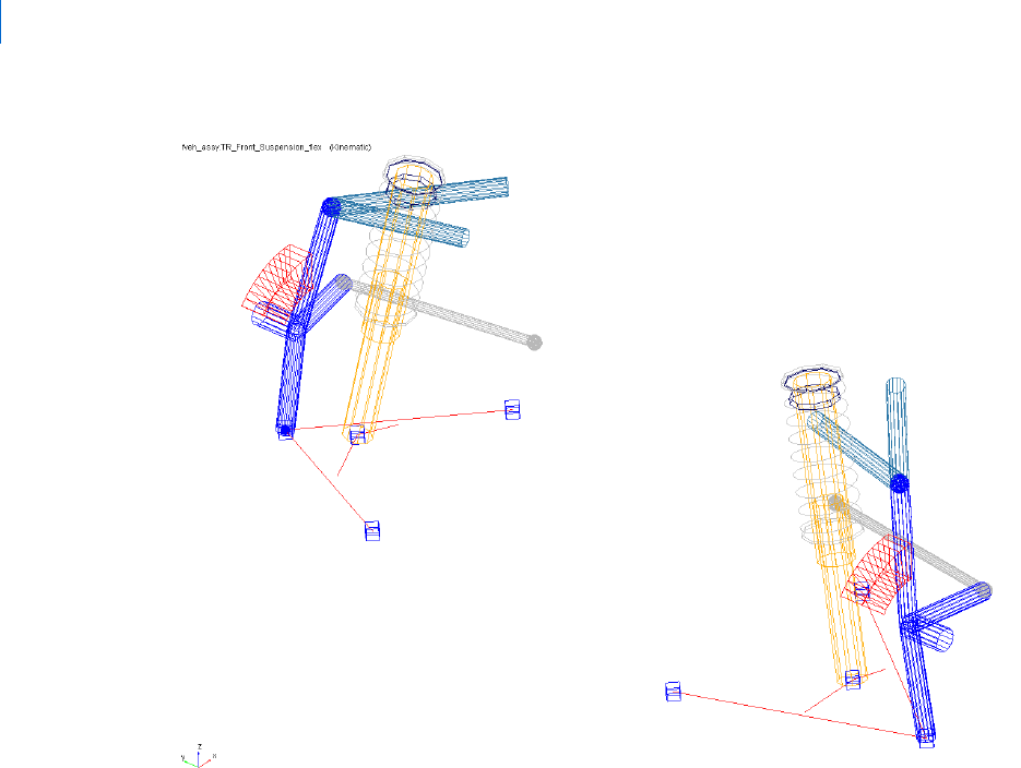
Getting Started Using Adams Car
Working with Flexible Bodies in Full-Vehicle Assemblies
70
Figure 8 Modified Flexible Lower Control Arm
8. To return to the full-vehicle assembly, from the View menu, select Assembly.
9. Select OK.
Changing Modal Content
By default, when you integrate an MNF into an Adams Car template, Adams Flex enables all the modes that
were defined during the FEM modeling except the probable rigid body modes. It is important to have the
right modal content in flexible bodies, because an MNF has more modes than are needed to simulate a
particular response.
To increase the efficiency of the simulations, you should disable any modes that do not contribute to the
motion that your flexible part will undergo during the simulation. Be careful when disabling modes, because
a disabled mode corresponds to a constraint to the part. Changing the modal content of a flexible body
corresponds to a flexible body setup.
You can manually toggle modes on or off. This gives you greater flexibility and helps you avoid potential
problems. You can enable and disable modes in several ways:
Individually, based on their mode number.

71
Flexible Bodies Tutorial
Working with Flexible Bodies in Full-Vehicle Assemblies
As a group, based on their mode number or frequency.
Through a table editor. The table editor also lets you define displacement and velocity initial
conditions associated with every mode.
Based on their strain energy contribution, but you can only do this after a successful analysis. For
more information on this technique, see the Adams Flex online help.
To disable individual modes:
Some of the modes of the flexible lower control arms do not contribute effectively to the dynamic behavior
of the entire system. We recommend that you disable them to reduce the computational effort and to improve
the efficiency of the simulation.
You must disable these modes for both the left and the right side because a left and a right MNF defines the
flexible lower control arms.
1. Zoom in on the front suspension.
2. From the Adjust menu, point to Flexible body, and then select Mode Manager.
The Flexible Body Modify dialog box appears.
3. Right-click the Flexible Body text box, point to Flexible body, point to Pick, and from the screen,
select the left lower control arm, fbl_lower_control_arm.
4. Select Modal ICs.
The Modify Modal ICs dialog box appears.
5. Hold down the Shift key, select modes 35 and 36, and then select Disable Highlighted Modes.
6. Close the Modify Modal ICs dialog box.
7. Repeat Steps 3 through 6, for the right lower control arm, fbr_lower_control_arm.
8. Close the Flexible Body Modify dialog box.
Performing a Full-Vehicle Analysis
You are now ready to perform the full-vehicle analysis. After you perform the analysis, you can change the
inertia modeling of the flexible body to compare the effect of the modal flexibility on the dynamics of the
vehicle.
To perform the full-vehicle analysis:
1. From the Simulate menu, point to Full-Vehicle Analysis, point to Open-Loop Steering Events, and
then select Step Steer.
2. Set up the analysis as follows:
• Full-Vehicle Assembly: fveh_assy
• Output Prefix: tst
• End Time: 4
• Number of Steps: 400

Getting Started Using Adams Car
Working with Flexible Bodies in Full-Vehicle Assemblies
72
• Mode of Simulation: interactive
• Road Data File: mdids://acar_shared/roads.tbl/2d_flat.rdf
• Initial Velocity: 70 (take the default of km/hr)
• Gear Position: 3
• Turn Direction: Right
• Method: Default
• Final Steer Value: 45
• Step Start Time:1
• Duration of Step: 1
• Steering Input: Angle
3. Keep the defaults for Cruise Control (off) and Quasi-Static Straight Line Setup (on).
4. Select Apply, so the dialog box stays open for the analysis you will run in the next section.
The SDI test rig applies to the assembly the inputs you specified and performs a dynamic analysis.
To change the inertia modeling:
1. Double-click the left lower control arm, fbl_lower_control_arm.
2. Select the Mode Manager tool.
3. Set Inertia modeling to Rigid body.
4. Select OK.
5. Close the Modify Flexible Body dialog box.
6. Submit another step steer analysis using the same inputs as before, but changing the output prefix to
tst_rigid.
Adams Car analyzes the assembly.
Plotting Analysis Results
In this section, you create a set of plots that show the behavior of your vehicle assembly and then review how
the modal flexibility of the lower control arm affects the overall dynamics of the vehicle.
To plot the results:
1. Launch Adams PostProcessor.
2. From the Plot menu, select Create Plots.
3. Fill in the dialog box as shown next, and then select OK.

73
Flexible Bodies Tutorial
Working with Flexible Bodies in Full-Vehicle Assemblies
Figure 9 File Import
Figure 10 and Figure 11 show some of the plots. The flexible lower control arms cause the differences
between the curves.
4. View the plots shown next and then return to Adams Car.
Figure 10 Lateral Slip Angle
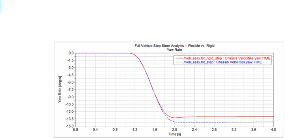
Getting Started Using Adams Car
Working with Flexible Bodies in Full-Vehicle Assemblies
74
Figure 11 Yaw Rate

79
Template Builder Tutorial
What You Will Create and Analyze
Template Builder Tutorial
This tutorial guides you through the process of building a template, creating a suspension subsystem based
on the template, and then running various analyses on the subsystem. To build the template, you must use
Adams Car Template Builder.
This chapter includes the following sections:
What You Will Create and Analyze
Creating Topology for Your Template
Creating a Suspension Subsystem
Analyzing an Assembly Containing Your Template
This tutorial takes about two hours to complete.
What You Will Create and Analyze
To learn how to create templates, you create a complete MacPherson front suspension template, as shown in
Figure 1 (note that we toggled the icon visibility off and the shading on). You then build a suspension using
the template you created. Finally, you run kinematic and compliant suspension analyses and compare their
results.

Getting Started Using Adams Car
Creating Topology for Your Template
80
Figure 1 MacPherson Front Suspension Template
Creating Topology for Your Template
Before you begin to build your template, you must decide what elements are most appropriate for your
model. You must also decide which geometries seem most applicable to each part or whether you want any
geometry at all. Once you’ve decided, you create a template and create the basic topology for it. Finally, you
assemble the model for analysis.
Damper
Control arm
Wheel
Carrier
Attachment
bushing
Spring
Tie rod
Hub

81
Template Builder Tutorial
Creating Topology for Your Template
This section involves the following steps:
Creating a Template
Building Suspension Parts
Creating and Defining Attachments and Parameters
Assembling the Model for Analysis
Finishing Up
Creating a Template
You must create a template in which to build suspension parts. You should assign to your template a major
role as a suspension template, because a major role defines the function the template serves for the vehicle.
To create a template:
1. Start Adams Car Template Builder as explained in Starting Adams Car Template Builder.
2. From the File menu, select New.
3. In the Template Name text box, enter macpherson.
4. Verify that Major Role is set to suspension.
5. Select OK.
A gravity icon appears in the middle of the Adams Car main window as shown in the following figure.
If you don’t see a gravity icon, display the main shortcut menu by right-clicking the main window,
and selecting Toggle Icon Visibility. You can also toggle the icon visibility on and off by placing the
cursor in the main window and typing a lowercase v.
6. From the main shortcut menu, select Front Iso and Fit - All. Fit your model to view whenever you
create an entity outside the current view.
The Adams Car main window should look as follows:
Tip: For information on any dialog box, press F1 when the dialog box is active.

Getting Started Using Adams Car
Creating Topology for Your Template
82
Figure 2 Main Window with Gravity Icon Displayed
Building Suspension Parts
You create parts in Adams Car through a three-step process. First, you create hardpoints that define key
locations on the part. Then, you create the actual part. Finally, if you want, you add geometry to your new
part.
You can use one of two methods to create parts in Adams Car:
User-entered method lets you manually enter mass properties and material type for a part.
Geometry-based method lets you tell Adams Car to automatically create mass properties using the
geometry and material type that you specify.
In the next sections, you create all the parts that make up the suspension template:
Creating the Control Arm
Creating the Wheel Carrier

83
Template Builder Tutorial
Creating Topology for Your Template
Creating the Strut
Creating the Tie Rod
Creating the Toe and Camber Variables
Creating the Hub
Creating the Control Arm
The first part you define is the control arm. You begin by building its hardpoints. You can later modify these
hardpoints to determine their effects on your vehicle.
Next, you create the control arm part and specify its coordinate system location and mass properties.
To complete the creation of the control arm, you create geometry for it. You then define key locations for that
geometry so Adams Car can calculate its mass properties. In this tutorial, whenever you want Adams Car to
calculate mass properties, you select steel as the material type.
When specifying orientations in Adams Car, you can either enter Euler angles or specify two direction vectors.
In this tutorial, you will just use Euler angles with respect to the global orientation marker, which is named
origo.
To build the hardpoints:
1. From the Build menu, point to Hardpoint, and then select New.
2. In the Hardpoint Name text box, enter arm_outer.
3. Verify that Type is set to left.
In this tutorial, you set all entities to
left. Adams Car automatically creates a symmetrical pair about
the central longitudinal axis.
4. In the Location text box, enter 0, -700, 0.
5. Select Apply.
6. Adams Car creates the hardpoint, but leaves the Create Hardpoint dialog box open.
7. Repeat Steps 2 through 5 to build the two hardpoints specified in Table 2.
8. When you’re done creating the hardpoints, close the dialog box.
9. To see all six hardpoints in the main window, fit your model to view (type a lowercase f).
Note: Depending on how you set up your environment variables, the longitudinal axis can
be any axis. In this tutorial, the longitudinal axis is the x-axis. For information on
setting your environment variables, see the Adams Car online help.
Hardpoint Name: Location:
arm_front -150, -350, 0
arm_rear 150, -350, 0

Getting Started Using Adams Car
Creating Topology for Your Template
84
To create the control arm part:
1. From the Build menu, point to Parts, point to General Part, and then select New.
2. Fill in the dialog box as shown next, and then select OK.

85
Template Builder Tutorial
Creating Topology for Your Template
Adams Car creates a part coordinate system, also referred to as local part reference frame (LPRF,
which is also known as the Body Coordinate System (BCS)), at the specified location, but it doesn’t
create geometry.
To create the control arm geometry:
1. From the Build menu, point to Geometry, point to Arm, and then select New.
2. Create the control arm as follows:
• Arm Name: control_arm
• General Part: ._macpherson.gel_control_arm
• Coordinate Reference #1: ._macpherson.ground.hpl_arm_outer
• Coordinate Reference #2: ._macpherson.ground.hpl_arm_front
• Coordinate Reference #3: ._macpherson.ground.hpl_arm_rear
• Thickness: 10
3. Select Calculate Mass Properties of General Part.
4. Set Density to Material.
5. Select OK.
Adams Car displays the control arm part. If you want the control arm to be shaded, put the cursor in
the main window and type an uppercase S. This toggles the rendering mode between shaded and
wireframe.
Creating the Wheel Carrier
To create the wheel carrier, you must first create three hardpoints that define the location of the wheel carrier.
You then define the wheel carrier part using these hardpoint locations.
Next, you add link geometry to the wheel carrier. When you add the link geometry, you enter parameters that
are similar to those you specified for the arm geometry, except that a link only requires two coordinate
reference points to define its geometry.
To create the hardpoints:
1. From the Build menu, point to Hardpoint, and then select New.
Note: Based on the geometry, the option Calculate Mass Properties of General Part
computes the mass properties for the part, and adds that to the total mass of the part.
(You can have more than one geometry associated with a part.) Also, note that the
mass of the part is not parameterized to its geometry. Therefore, if you want to base
the mass of the part on new geometry, you must use the Calculate Mass functionality
for the part.

Getting Started Using Adams Car
Creating Topology for Your Template
86
2. Create the wheel carrier hardpoints as specified in Table 1. Remember that you can select Apply to
execute the command but leave the dialog box open, and select OK to execute the command and then
close the dialog box.
3. To display the hardpoints in the main window, fit your model to view.
To create the wheel carrier part:
1. From the Build menu, point to Parts, point to General Part, and then select Wizard.
2. Create the wheel carrier part as follows:
• General Part Name: wheel_carrier
• Geometry Type: Arm
• Coordinate Reference #1: ._macpherson.ground.hpl_wheel_center
• Coordinate Reference #2: ._macpherson.ground.hpl_arm_outer
• Coordinate Reference #3: ._macpherson.ground.hpl_strut_lower
• Thickness: 10
3. Select OK.
The wizard creates both the part and the geometry.
To add the wheel carrier link geometry:
1. From the Build menu, point to Geometry, point to Link, and then select New.
2. Create the wheel carrier part as follows:
• Link Name: carrier_link
• General Part: ._macpherson.gel_wheel_carrier
• Coordinate Reference #1: ._macpherson.ground.hpl_strut_lower
• Coordinate Reference #2: ._macpherson.ground.hpl_tierod_outer
• Radius: 10
3. Select Calculate Mass Properties of General Part.
4. Select OK.
Table 1 Wheel carrier hard points
Hardpoint Name: Location:
wheel_center 0, -800, 100
strut_lower 0, -650, 250
tierod_outer 150, -650, 250
Note: Remember that all these hardpoints are left-side hardpoints.

87
Template Builder Tutorial
Creating Topology for Your Template
The template now includes the wheel carrier part and the link geometry.
Creating the Strut
In this section, you create the strut part for your suspension template. Just as you did for the control arm, you
enter the location, orientation, and mass properties for the strut part.
Because the strut geometry would not be visible from inside the damper, you don’t need to give the strut any
geometry.
To define the strut part:
1. From the Build menu, point to Parts, point to General Part, and then select New.
2. Define the strut part as follows:
• General Part: strut
• Location values: 0, -600, 600
• Euler Angles: 0, 0, 0
• Mass/Ixx/Iyy/Izz: 1
3. Select OK.
Creating the Tie Rod
You first create a hardpoint and then use it to define the tie rod part.
To create a hardpoint:
1. Create a hardpoint with the following specifications:
• Hardpoint Name: tierod_inner
• Location: 200, -350, 250
2. Select OK.
To create the tie rod part:
1. From the Build menu, point to Parts, point to General Part, and then select Wizard.
2. Create the tie rod part as follows:
• General Part Name: tierod
• Geometry Type: Link
• Coordinate Reference #1: ._macpherson.ground.hpl_tierod_outer
• Coordinate Reference #2: ._macpherson.ground.hpl_tierod_inner
• Radius: 10
3. Select OK.
The template now includes the tie rod part.

Getting Started Using Adams Car
Creating Topology for Your Template
88
Creating the Toe and Camber Variables
You create variables defining toe and camber angles. Because these variables are commonly used for
suspension analyses, Adams Car creates both of them in one step.
To create toe and camber variables:
1. From the Build menu, point to Suspension Parameters, point to Toe/Camber Values, and then
select Set.
2. Fill in the dialog box as shown next, and then select OK.
Creating the Hub
Before you create the hub part for your template, you must create a construction frame. Construction frames
are Adams Car elements that you use whenever an entity requires that you specify an orientation in addition
to a location.
You create the hub based on the construction frame, and then create geometry for the hub.
To create a construction frame:
1. From the Build menu, point to Construction Frame, and then select New.
2. Create a construction frame as follows:
• Construction Frame: hub_bearing
• Location Dependency:Delta location from coordinate
• Coordinate Reference: ._macpherson.ground.hpl_wheel_center
• Orientation Dependency: Toe/Camber
• Toe Parameter Variable: ._macpherson.pvl_toe_angle
• Camber Parameter Variable: ._macpherson.pvl_camber_angle
3. Select OK.
Note: When Adams Car creates the toe and camber values, it also creates output communicators
of the same name. For details on communicators, see Assembling the Model for Analysis.

89
Template Builder Tutorial
Creating Topology for Your Template
To create the hub part:
1. From the Build menu, point to Parts, point to General Part, and then select New.
2. Create the hub part as follows:
• General Part: hub
• Location Dependency:Delta location from coordinate
• Coordinate Reference: cfl_hub_bearing
• Location values: 0, 0, 0
• Orientation Dependency: Delta orientation from coordinate
• Construction Frame: cfl_hub_bearing
• Orientation: 0, 0, 0
• Mass/Ixx/Iyy/Izz: 1
3. Select OK.
To create cylinder geometry for the hub:
1. From the Build menu, point to Geometry, point to Cylinder, and then select New.
2. Create the cylinder geometry as follows:
• Cylinder Name: hub
• General Part: ._macpherson.gel_hub
• Construction Frame: ._macpherson.ground.cfl_hub_bearing
• Radius: 30
• Length in Positive Z: 30
• Length in Negative Z: 0
• Color: magenta
3. Select Calculate Mass Properties of General Part.
4. Select OK.
The template now includes the hub.
Creating Forces
In this section, you create a damper and a spring.
Creating the Damper
You first create a hardpoint and then use it to define the damper. You then create a damper that is defined by
a property file that we provide for you. Property files define force-displacement, force-velocity, and other
kinds of characteristics for springs, dampers, bumpstops, reboundstops, and bushings. In this case, the
property file defines the damper’s force-velocity curve.

Getting Started Using Adams Car
Creating Topology for Your Template
90
To create a hardpoint:
1. Create a hardpoint as follows:
• Hardpoint Name: strut_upper
• Location: 0, -600, 600
2. Select OK.
To create the damper:
1. From the Build menu, point to Forces, point to Damper, and then select New.
2. Create the damper as follows:
• Damper Name: damper
• I Part: ._macpherson.gel_wheel_carrier
• J Part: ._macpherson.gel_strut
• I Coordinate Reference: ._macpherson.ground.hpl_strut_lower
• J Coordinate Reference: ._macpherson.ground.hpl_strut_upper
3. Select OK.
Defining the Spring
Before you define the spring, you have to create a hardpoint that defines the position of the lower spring seat.
Then, to define the spring, you must specify the following:
Two bodies between which you want the force to act.
Specific location on each body where you want the force to act.
Installed length of the spring, which will be used to derive the design preload on the spring.
Property file, which contains the free length information, as well as the force/deflection
characteristics.
Adams Car calculates the force exerted by the spring using the following equations:
C = FL - IL + DM’(i,j)
Force = -k(C - DM(i,j))
where:
C is a constant.
FL is the free length of the spring, as defined in the property file.
IL is the defined installed length.
DM(i,j) is the change in the displacement between the i and j coordinate reference points as the
simulation progresses.
DM’(i,j) is the initial displacement between the i and j coordinate reference points. If you enter a
smaller value for
DM(i,j), Adams Car calculates an increased preload for the spring. Conversely, if
you enter a larger value, Adams Car calculates a decreased preload. In this tutorial, you enter the
value that Adams Car automatically calculates for you.

91
Template Builder Tutorial
Creating Topology for Your Template
Force represents the spring force.
k is the nonlinear spring stiffness derived from the property file.
To create a hardpoint for the spring:
1. Create a hardpoint as follows:
• Hardpoint Name: spring_lower
• Location: 0, -650, 300
2. Select OK.
To create the spring:
1. From the Build menu, point to Forces, point to Spring, and then select New.
2. Fill in the dialog box as shown next, and then select OK.

Getting Started Using Adams Car
Creating Topology for Your Template
92
The template now includes the damper and the spring.
Creating and Defining Attachments and Parameters
Now that you created all the Adams Car parts, springs, and dampers, you are ready to define attachments and
parameters.
This section includes the following:
Defining the Translational Joint

93
Template Builder Tutorial
Creating Topology for Your Template
Defining Control Arm Attachments
Defining the Strut Attachment
Defining Wheel Carrier Attachments
Defining Hub Attachments
Defining Suspension Parameters
Defining the Translational Joint
You first create a translational joint between the wheel carrier and the strut. You specify that this joint is active
regardless of the mode in which you simulate your model.
In Adams Car, you can simulate your model in kinematic or compliant mode. A kinematic analysis uses
constraints, such as translational and revolute joints, to define the attachments between the parts. During a
compliant analysis, Adams Car replaces these joints with bushings. The joint-bushing swap only occurs if the
joint and/or bushing has been defined to be active and/or inactive, respectively, when defining the
attachment.
To define a translational joint:
1. From the Build menu, point to Attachments, point to Joint, and then select New.
2. Create the translational joint as follows:
• Joint Name: strut_joint
• I Part: ._macpherson.gel_wheel_carrier
• J Part: ._macpherson.gel_strut
• Joint Type: translational
• Coordinate Reference: ._macpherson.ground.hpl_strut_upper
• Orientation Dependency: Orient axis along line
• Coordinate Reference #1: ._macpherson.ground.hpl_strut_lower
• Coordinate Reference #2: ._macpherson.ground.hpl_strut_upper
3. Select OK.
Defining Control Arm Attachments
Before you create bushings and joints for the control arm, you must create the mount parts that act as
placeholders for the attachments. A mount part is a massless part that is fixed to ground. The purpose of a
mount part is to be replaced by another part (for example, vehicle body, subframe, wheel, and so on) if its
associated input communicator(s) find matching output communicator(s), or to be replaced by ground if no
matching output communicator is found.
When you create a mount part, Adams Car automatically creates an input communicator for it of class
mount. The input communicator requests the name of the part to which the mount part should connect. If
Adams Car finds a matching communicator during assembly, it replaces the mount part with the part that
the output communicator indicates. The replacement part is from another subsystem. If Adams Car finds no
matching output communicator, it replaces the mount part with the ground part.

Getting Started Using Adams Car
Creating Topology for Your Template
94
To create a mount part, you specify a hardpoint and mount part name. If the hardpoint has a left or right
symmetrical twin, Adams Car creates left and right mount parts and input communicators. Otherwise, it
creates a single mount part and a single input communicator.
After you create the mount parts, you create bushings for the control arm. You specify the parameters, such
as preload and offset, that define bushings. In this example, you use the default values that Adams Car
provides. If you want, you can modify the bushing properties. You also set its inactive status to kinematic, so
that during a kinematic analysis Adams Car deactivates this bushing.
Finally, you create the control arm revolute joint. This time, you set its active status to kinematic. This tells
Adams Car that during a kinematic analysis it should use the revolute joint, but it should replace the joint
with a bushing during a compliant analysis.
To create the mount parts:
1. From the Build menu, point to Parts, point to Mount, and then select New.
2. In the Mount Name text box, enter subframe_to_body.
3. In the Coordinate Reference text box, enter ._macpherson.ground.hpl_arm_front.
4. Verify that From Minor Role is set to inherit.
5. Select OK.
Adams Car creates fixed joints between the mount parts and ground. By default, the visibility of the
fixed joints is turned off.
To create the front bushing for the control arm:
1. From the Build menu, point to Attachments, point to Bushing, and then select New.
2. Fill in the dialog box as shown next, and then select Apply.

95
Template Builder Tutorial
Creating Topology for Your Template

Getting Started Using Adams Car
Creating Topology for Your Template
96
Adams Car creates the front bushing and leaves the dialog box open so you can create the rear
bushing.
To create the rear bushing for the control arm:
1. In the Bushing Name text box, enter arm_rear.
2. In the Coordinate Reference text box, enter ._macpherson.ground.hpl_arm_rear.
3. Select OK.
Adams Car creates the rear bushing.
To create the control arm revolute joint:
1. Create the control arm revolute joint as follows:
• Joint Name: arm_front
• I Part: ._macpherson.gel_control_arm
• J Part: ._macpherson.mtl_subframe_to_body
• Joint Type: revolute
• Active:kinematic mode
• Coordinate Reference: ._macpherson.ground.hpl_arm_front
• Orientation Dependency: Orient axis along line
• Coordinate Reference #1: ._macpherson.ground.hpl_arm_front
• Coordinate Reference #2: ._macpherson.ground.hpl_arm_rear
2. Select Apply.
To create the control arm spherical joint:
1. Create the control arm spherical joint as follows:
• Joint Name: arm_outer
• I Part: ._macpherson.gel_wheel_carrier
• J Part: ._macpherson.gel_control_arm
• Joint Type: spherical
• Active:always
• Coordinate Reference: ._macpherson.ground.hpl_arm_outer
2. Select OK.
Defining the Strut Attachment
Before you define the strut attachments to the vehicle body, you must define a mount part for the strut. You
then create a bushing for the strut. Next, you create a spherical joint to replace the strut mount bushing
during kinematic analyses.

97
Template Builder Tutorial
Creating Topology for Your Template
To define a mount part:
1. Create a mount part as follows:
• Mount Name: strut_to_body
• Coordinate Reference: ._macpherson.ground.hpl_strut_upper
• From Minor Role: inherit
2. Select OK.
To create a bushing for the strut:
1. Create the bushing as shown next, and then select OK.

Getting Started Using Adams Car
Creating Topology for Your Template
98

99
Template Builder Tutorial
Creating Topology for Your Template
To create a spherical joint for the strut:
1. Create the spherical joint as follows:
• Joint Name: strut_upper
• I Part: ._macpherson.gel_strut
• J Part: ._macpherson.mtl_strut_to_body
• Joint Type: spherical
• Active:kinematic mode
• Coordinate Reference: ._macpherson.ground.hpl_strut_upper
2. Select Apply.
Defining Wheel Carrier Attachments
In this section, you define a spherical joint between the wheel carrier and the tie rod. You then define the
mount part that connects the suspension to the steering rack during assembly. Finally, you create a hooke
joint between the tie rod and the steering rack.
To create a spherical joint:
1. Create the spherical joint as follows:
• Joint Name: tierod_outer
• I Part: ._macpherson.gel_wheel_carrier
• J Part: ._macpherson.gel_tierod
• Joint Type: spherical
• Active:always
• Coordinate Reference: ._macpherson.ground.hpl_tierod_outer
2. Select OK.
To create a mount part for the hooke joint:
1. Create a mount part as follows:
• Mount Name: tierod_to_steering
• Coordinate Reference: ._macpherson.ground.hpl_tierod_inner
• From Minor Role: inherit
2. Select OK.
To create a hooke joint:
1. Create a hooke joint as follows:
• Joint Name: tierod_inner
• I Part: ._macpherson.gel_tierod

Getting Started Using Adams Car
Creating Topology for Your Template
100
• J Part: ._macpherson.mtl_tierod_to_steering
• Joint Type: hooke
• Active: always
• Coordinate Reference: ._macpherson.ground.hpl_tierod_inner
• I-Part Axis:._macpherson.ground.hpl_tierod_outer
• J-Part Axis: ._macpherson.ground.hpr_tierod_inner
2. Select Apply.
Defining Hub Attachments
You can now define the hub bearing revolute joint between the wheel carrier and the hub.
To define the hub attachment:
1. Create a revolute joint as follows:
• Joint Name: hub_bearing
• I Part: ._macpherson.gel_wheel_carrier
• J Part: ._macpherson.gel_hub
• Joint Type: revolute
• Active:always
• Coordinate Reference: ._macpherson.ground.hpl_wheel_center
• Orientation Dependency: Delta orientation from coordinate
• Construction Frame: ._macpherson.ground.cfl_hub_bearing
2. Select OK.
Defining Suspension Parameters
You create a steering axis using the geometric method for calculating steer axes. When using the geometric
method, Adams Car calculates the steer axis by passing a line through two non-coincident hardpoints located
on the steer axis. To use the geometric method, you must identify the part(s) and two hardpoints that fix the
steer axis.
To create a steer axis:
1. From the Build menu, point to Suspension Parameters, point to Characteristic Array, and then
select Set.
2. Fill in the dialog box as shown next, and then select OK.
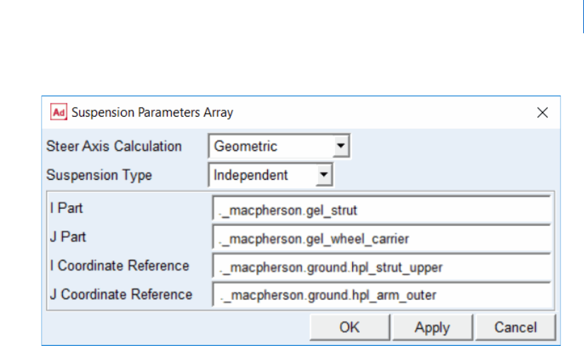
101
Template Builder Tutorial
Creating Topology for Your Template
Assembling the Model for Analysis
Adams Car uses communicators to correctly assemble the model for analysis. Communicators are the Adams
Car elements that allow the subsystems and test rigs to exchange information about the following:
Topological data, meaning information about parts and attachments.
Array and parameter variables.
Locations, orientations, and so on.
Every subsystem or test rig in Adams Car has input communicators that need information from other
subsystems to function correctly in the model. Similarly, the corresponding subsystem or test rig, needs to
have a correctly named output communicator that will send it information. For example, an input
communicator needs information on the location of a hardpoint. A corresponding output communicator
provides the location information.
During the assembly process, Adams Car scans the model for subsystems with minor roles. It then looks
through those subsystems for any input communicators that require information. It then tries to find an
output communicator, of the same entity type, with the same matching name. If it can’t find one, it won’t
match the communicators and the model may be incorrectly assembled.
For example, whenever you create a mount part in your template, Adams Car automatically creates a
corresponding input communicator. During assembly, this input communicator should match the correct
output mount communicator located in the test rig. If Adams Car finds no matching output communicator,
it replaces the mount part with the ground part.
Adams Car automatically creates an input communicator corresponding to that mount on the test rig. Then,
you need to create a matching output communicator on the template you are creating. These communicators
must have the exact same name for Adams Car to know which communicators to use. This is explained in
detail in Defining Communicators.

Getting Started Using Adams Car
Creating Topology for Your Template
102
In this section, you create and verify output communicators:
Defining Communicators
Testing Communicators
Defining Communicators
For the assembly process to work correctly, you must define how the suspension is to connect to the
suspension test rig (
_MDI_SUSPENSION_TESTRIG). To do this, you define the communicators that attach
the hub to the suspension test rig at the wheel center, as follows:
To tell the suspension test rig to which part it needs to be connected, you define an output
communicator of type
mount. This communicator accomplishes two tasks:
• Communicates the part to which the testrig is being connected.
• Defines the I part of the static lock actuator.
To tell the suspension test rig where the connection takes place, you define an output communicator
of type
location.
To tell the suspension test rig which is the upright part (wheel carrier), to create a static lock
actuator, you define an output communicator of type
mount. This communicators defines the J part
of the static lock actuator.
When you analyze the suspension in static mode, you must lock the hub to the wheel carrier. If you don’t lock
the hub to the wheel carrier, your assembly will have a rotational degree of freedom that prevents the analysis
from converging to a solution. Adams Car creates the actuator between the hub and the upright (wheel
carrier), automatically based on the communicators mentioned above.
To display information about communicators:
1. From the Build menu, point to Communicator, and then select Info.
2. Clear the Model Names text box.
3. Right-click the Model Names text box, point to Model, point to Guesses, and then select
.__MDI_SUSPENSION_TESTRIG.
4. Select array, location, and mount.
5. Select OK.
The Information window appears as shown next:

103
Template Builder Tutorial
Creating Topology for Your Template
The Information window lists the mount input communicators. Notice that Adams Car
automatically adds the prefix ci[lr] (which designates communicator input left or right) to the name
of input communicators. If you want to see the entire contents of the Information window, use the
vertical scroll bar. If you want to see the matching name for each communicator, use the horizontal
scroll bar.
6. Select Close.
To create the output communicators:
1. From the Build menu, point to Communicator, point to Output, and then select New.
2. In the Output Communicator Name text box, enter suspension_mount.
3. Set Entity to mount.
4. Verify that To Minor Role is set to inherit.

Getting Started Using Adams Car
Creating Topology for Your Template
104
5. In the Part Name text box, enter ._macpherson.gel_hub.
6. Select Apply.
Adams Car selects the hub as the part to which the test rig connects.
7. In the Output Communicator Name text box, enter suspension_upright.
8. In the Part Name text box, enter ._macpherson.gel_wheel_carrier.
9. Select Apply.
10. In the Output Communicator Name text box, enter wheel_center.
11. Set Entity to location.
12. Verify that To Minor Role is set to inherit.
13. In the Coordinate Reference Name text box, enter ._macpherson.ground. hpl_wheel_center.
14. Select OK.
Adams Car will use this location communicator to select the location on the hub to which the test rig
connects.
Testing Communicators
To verify that you correctly specified the input and output communicators, you can test communication in
your template. Testing your communicators lets you find out whether to add or modify communicators to
ensure that your suspension template will assemble properly with the suspension test rig.
To test the communicators:
1. From the Build menu, point to Communicator, and then select Test.
2. Fill in the dialog box as shown next, and then select OK.
Note: Adams Car allows you to specify one or more Matching Names so that you can
designate different communicators for the front and rear subsystems in case you might
be using the same template for both subsystems. In this case, you’ll just leave it blank
since Adams Car defaults to assigning the communicator name as the matching name
if none is specified.

105
Template Builder Tutorial
Creating Topology for Your Template
The Information window appears as shown next:

Getting Started Using Adams Car
Creating Topology for Your Template
106
The Information window lists which communicators are matched, and which are not. First, it shows
you the matched communicators that are correctly sending and receiving information between
subsystems and test rigs. Notice that the mount communicators for
suspension_mount,
suspension_upright, and wheel_center are listed in the matched communicator section.
The Information window also lists input and output communicators that are not matched correctly.
Many communicators are unmatched. Many of these communicators are related to items such as the
steering or chassis that we do not currently have open. When you start creating your own templates,
you can use the Information window to verify that you included all necessary communicators.
3. Select Close.
Finishing Up
After you finish building the template, save it in your private database so you can use it later to create
suspension subsystems. Adams Car assigns the extension
.tpl to your template.
After you save your template, you can exit template-builder mode and start the Adams Car Standard
Interface.

107
Template Builder Tutorial
Creating a Suspension Subsystem
To save the suspension template:
From the File menu, select Save.
To exit template-builder mode:
From the Tools menu, select Adams Car Standard Interface.
Adams Car returns to standard-interface mode, where you can create the suspension subsystem.
Creating a Suspension Subsystem
In this section, you create an Adams Car suspension subsystem that is based on the template you just built.
You also modify some hardpoints and translate the subsystem to ensure that Adams Car correctly positions
the subsystem within the assembly.
To create a subsystem:
1. From the File menu, point to New, and then select Subsystem.
2. Fill in the dialog box as shown next, and then select OK.
Adams Car displays the following message:
The template _macpherson exists in memory. Do you want to use it?
3. Select Yes.
Adams Car displays the subsystem.
To modify hardpoints:
1. From the Adjust menu, point to Hardpoint, and then select Table.

Getting Started Using Adams Car
Analyzing an Assembly Containing Your Template
108
2. Modify the hardpoint values to match those listed in Table 2:
3. Select Apply.
4. Select Cancel.
To save the subsystem:
From the File menu, select Save.
Analyzing an Assembly Containing Your Template
In this section, you perform two types of suspension analyses and plot the results.
We assume that you already completed the previous tutorials, and know how to incorporate your new
template into an analysis.
You perform the following types of analyses:
Performing a Kinematic Analysis
Performing an Elasto-Kinematic Analysis
Performing a Kinematic Analysis
When you perform a kinematic analysis, you use the joints, rather than the bushings, that you defined when
you built your template.
Before you can perform the kinematic analysis, you must create a suspension assembly. After you create the
suspension assembly, define a preload.
To create a suspension assembly:
1. From the File menu, point to New, and then select Suspension Assembly.
2. In the Assembly Name text box, enter susp_assy_1.
3. Verify that Suspension Subsystem is set to the name of your subsystem,
my_macpherson. If it is
not, click the folder icon next to Suspension Subsystem.
The name of your subsystem,
my_macpherson, appears next to the icon.
4. Select OK.
Table 2 Hardpoint table
Name: loc_x: loc_y: loc_z:
hpl_arm_front -200 -400 225
hpl_arm_rear 200 -390 240
hpl_tierod_inner 200 -400 300
hpl_tierod_outer 150 -690 300

109
Template Builder Tutorial
Analyzing an Assembly Containing Your Template
5. When Adams Car finishes creating the assembly, select Close.
To define a preload:
1. Right-click either spring, point to the name of the spring, and then select Modify.
2. Set Installed Length to 135.0.
3. Select OK.
To change to kinematic mode:
1. From the Adjust menu, select Kinematic Toggle.
The Toggle Kinematic Mode text box should already contain the name of your subsystem.
2. Set Current Mode to Kinematic.
3. Select OK.
To perform a kinematic suspension analysis:
1. From the Simulate menu, point to Suspension Analysis, and then select Parallel Wheel Travel.
2. Fill in the dialog box as shown next, and then select OK.

Getting Started Using Adams Car
Analyzing an Assembly Containing Your Template
110
Adams Car performs the analysis and displays messages about the simulation.
3. When the analysis is complete, select Close.
To animate the results:
1. From the Review menu, select Animation Controls.
2. Select the Play tool .
The suspension animates through full jounce and rebound.
To plot the results:
1. Launch Adams PostProcessor just as you did in Plotting Results.

111
Template Builder Tutorial
Analyzing an Assembly Containing Your Template
2. From the Plot menu, select Create Plots.
3. Set up the plots as follows:
• Plot Configuration File:
mdids://shared_acar/plot_configs.tbl/mdi_suspension_parallel_travel.plt
• Plot Title: My MacPherson
4. Verify that Cross Plotting is not selected.
5. Select OK.
Adams Car automatically generates a series of plots based on this plot configuration file.
6. Cycle through the plots using the plot navigation tools.
Figure 3 shows the Toe Angle plot.
Figure 3 Plot of Toe Angle - Kinematic Analysis
7. After viewing the plots, return to Adams Car.

Getting Started Using Adams Car
Analyzing an Assembly Containing Your Template
112
Performing an Elasto-Kinematic Analysis
To run an elasto-kinematic analysis, you must first switch the mode from kinematic to compliant. This turns
off kinematic constraints and uses bushings for attachments between the parts.
Next, you must modify analysis parameters, and then run the analysis.
After the analysis is complete, you return to Adams PostProcessor to compare analysis results.
To change to compliant mode:
1. From the Adjust menu, select Kinematic Toggle.
2. Set Current Mode to Compliant.
3. Select OK.
To perform an elasto-kinematic analysis:
1. From the Simulate menu, point to Suspension Analysis, and then select Parallel Wheel Travel.
2. Set the Output Prefix to ela.
3. Select OK.
Adams Car performs the analysis and displays messages about the simulation.
To plot the results of the elasto-kinematic analysis:
1. In Adams PostProcessor, set up the comparison plots as follows:
• Plot Configuration File:
mdids://acar_shared/plot_configs.tbl/mdi_suspension_parallel_travel.plt
• Plot Title: My MacPherson
2. Select Cross Plotting.
3. Select OK.
Adams Car creates plots with both analyses results included on each plot.
Figure 4 shows a comparison plot for the toe angle.

113
Template Builder Tutorial
Analyzing an Assembly Containing Your Template
Figure 4 Toe Angle - Comparison Plot
Note that the elastic toe angle is greater than the toe angle as measured in kinematic mode.

Getting Started Using Adams Car
Analyzing an Assembly Containing Your Template
114

119
Full-Vehicle Analysis Tutorial
Overview
Full-Vehicle Analysis Tutorial
Overview
This tutorial teaches you how to create a full-vehicle assembly, run different types of analyses, and view the
results.
To be able to run through this tutorial, you must have purchased the Adams Car Vehicle Dynamics Package.
This tutorial includes the following sections:
What You Will Create and Analyze
Opening a Full-Vehicle Assembly
Performing a Single Lane-Change Analysis
Performing a Quasi-Static Constant-Radius Cornering (CRC) Analysis
Performing a Baseline ISO Lane-Change Analysis
This tutorial takes about one hour to complete.
What You Will Create and Analyze
In this tutorial, you run several analyses on a full-vehicle assembly, as shown in Figure 1, and then view the
results using animation and plotting. To perform the analyses, you create an assembly containing all the
subsystems in the full vehicle.
Figure 1 shows the full-vehicle assembly (front iso view, fit to view).

Getting Started Using Adams Car
What You Will Create and Analyze
120
Figure 1 Full-Vehicle Assembly
After you create the full-vehicle assembly, you do the following:
To quantify how the vehicle responds to steering inputs, you perform a single lane-change (open-
loop) analysis on the vehicle. A single lane-change analysis controls the steering subsystem and
simulates a simple lane-change maneuver with the set of parameters you enter when you submit the
analysis.
To evaluate the vehicle’s understeer and oversteer characteristics, you run a constant radius
cornering analysis.
To drive the vehicle through a lane-change course as described in ISO-3888, you run an ISO lane-
change analysis.
After you run each analysis, you animate and plot its results.

121
Full-Vehicle Analysis Tutorial
Opening a Full-Vehicle Assembly
Opening a Full-Vehicle Assembly
Using Adams Car, you can group several subsystems and a test rig into an assembly. This grouping simplifies
the opening and saving of subsystems.
In this section, you open an assembly that references the subsystems and test rig for the full vehicle that you
are going to analyze. The assembly we’ve provided for you references the subsystems that Adams Car requires
to perform steering maneuvers, acceleration maneuvers, and so on. Full-vehicle assemblies reference the
following subsystems:
Front/rear suspensions
Steering subsystem
Powertrain
Brake subsystem
Front/rear tires
Rigid chassis
By default, Adams Car includes a vehicle test rig in the assembly.
To open an assembly:
1. Start Adams Car Standard Interface as described in Starting Adams Car Standard Interface.
2. From the File menu, point to Open, and then select Assembly.
3. Right-click the Assembly Name text box, point to Search, and then select the acar_shared database.
4. Double-click MDI_Demo_Vehicle.asy.
5. Select OK.
The Message Window appears, informing you that Adams Car is opening the assembly.
6. When Adams Car is done loading the assembly, select Close.
Adams Car displays the full-vehicle assembly.
Performing a Single Lane-Change Analysis
Now that you opened a full-vehicle assembly, you can submit a single lane-change analysis.
Performing a single lane-change analysis involves the following:
Setting Up the Analysis
Animating the Results
Plotting the Results
Modifying Plot Layouts
Tip: For information on any dialog box, press F1 when the dialog box is active.

Getting Started Using Adams Car
Performing a Single Lane-Change Analysis
122
Setting Up the Analysis
You can now specify the inputs for the full-vehicle analysis and perform a single lane- change maneuver. A
single lane-change maneuver inputs a one-cycle sinusoid to the steering wheel with the cycle length (time)
and maximum steer value (amplitude) you enter.
To set up the analysis:
1. From the Simulate menu, point to Full-Vehicle Analysis, point to Open-Loop Steering Events, and
then select Single Lane Change.
2. Fill in the dialog box as shown next, and then select OK.

123
Full-Vehicle Analysis Tutorial
Performing a Single Lane-Change Analysis
Adams Car updates the force entities, such as dampers, springs, and bushings, with the values
specified in their property files and sets up the vehicle assembly for the maneuver. Setting up the
vehicle assembly includes adjusting the road height so the road is in contact with the tires and
deactivating certain motions and forces, depending on the type of steering input you selected and the
inputs you specified. For example, because you set the steering input to angle, Adams Car deactivates
the torque on the steering wheel and the force on the rack, and activates a motion on the steering
wheel revolute joint.
The test rig, which is part of the assembly, applies the inputs you specified in the analysis submission
dialog box to the assembly, and performs a static analysis, followed by a dynamic analysis.
3. When the analysis is complete, select Close.
You are now ready to animate and plot the results.
Animating the Results
In this section, you view the analysis you just ran. Adams Car has already loaded the analysis results files for
you.
Before you animate, you might want to change the magnification of your assembly so you can see the path
the vehicle is taking.
To change the magnification of your assembly:
1. When the cursor is in the center of the main window, type a lowercase z.
2. Hold down the left mouse button, and do either of the following:
• To enlarge the display of the assembly, or zoom in, move the cursor up.
• To shrink the display of the assembly, or zoom out, move the cursor down.
3. To exit zoom mode, release the mouse button.
4. Animate the results just as you did in
Animating the Results.
5. If you want the vehicle to always be in the center of the screen, do the following:
• In Review pull down menu, select Animation Controls, Toggle Fixed Base to Base Part.
• Right-click the text box under Base Part, point to body, and then select Browse.
• The Database Navigator appears.
• From the list under MDI_Demo_Vehicle, double-click TR_Body, and then double-click
ges_chassis.
6. If you want to see the path the vehicle takes, do the following:
• Toggle No Trace to Trace Marker.
• Right-click the text box under Trace Marker, point to Marker, and then select Browse.
• The Database Navigator appears.
• Double-click TR_BODY.
• Double-click ges_chassis.

Getting Started Using Adams Car
Performing a Single Lane-Change Analysis
124
• Double-click cm.
7. To run another animation with either of the options presented in Steps
5. or 6., select the Play tool.
Adams Car animates the vehicle.
8. To return the assembly to its initial configuration, select the Reset tool .
Plotting the Results
In this section, you create two plots that represent the following:
Vehicle lateral acceleration as a function of time
Roll angle of the vehicle as a function of the lateral acceleration
To create a plot of the lateral acceleration with respect to time:
1. From the Review menu, select Postprocessing Window.
2. Verify that Source is set to Requests.
3. From the Simulation list, select fveh_test_sin.
4. From the Filter list, select user defined.
5. From the Request list, select chassis_accelerations. You might have to scroll to see this option.
6. From the Component list, select lateral.
7. Set the Independent Axis to Time.
8. Select Add Curves.
Adams PostProcessor displays the plot you requested, as shown next:

125
Full-Vehicle Analysis Tutorial
Performing a Single Lane-Change Analysis
Figure 2 Plot of Lateral Acceleration versus Time
To create a plot of the roll angle with respect to lateral acceleration:
1. From the Request list, select chassis_displacements.
2. From the Component list, select roll.
3. Set the Independent Axis to Data.
The Independent Axis Browser appears. You perform the next four steps in the browser.
4. From the Filter list, select user defined.
5. From the Request list, select chassis_accelerations. You might have to scroll to see this option.
6. From the Component list, select lateral.
7. Select OK.
8. From the dashboard, select Clear Plot.
9. Select Add Curves.
Adams PostProcessor displays the plot you requested, as shown next:
Figure 3 Plot of Roll Angle versus Lateral Acceleration
Modifying Plot Layouts
To make a plot ready for a report, you can assign a title or subtitle to the plot, just as you did in Plotting
Steering Wheel Torque versus Steering Wheel Angle.

Getting Started Using Adams Car
Performing a Quasi-Static Constant-Radius Cornering (CRC) Analysis
126
To assign a title or subtitle:
1. Assign the following title to your plot: Roll Angle versus Lateral Acceleration.
2. Assign the following subtitle to your plot: plot1.
3. Return to Adams Car.
Performing a Quasi-Static Constant-Radius Cornering
(CRC) Analysis
You use a CRC analysis to evaluate your full vehicle’s understeer characteristics. The CRC analysis holds the
turn radius constant and varies the vehicle’s lateral acceleration. A control subroutine,
CONSUB, controls the
analysis and balances all the forces on the body and applies a lateral acceleration to all model parts.
Submit a CRC analysis and view the results as explained in the following sections:
Setting Up the Analysis
Animating and Plotting the Results
Setting Up the Analysis
You can now specify the inputs for the full-vehicle analysis and perform a quasi-static maneuver.
To set up the analysis:
1. From the Simulate menu, point to Full-Vehicle Analysis, point to Static and Quasi-Static
Maneuvers, and then select Constant Radius Cornering.
2. Run an analysis with the following specifications:
• Output Prefix: fveh
• Number of Steps: 30
• Final Lateral Accel: .9
• Turn Radius: 50
• Set the units pull-down menu for the turn radius to m.
3. Select OK.
Adams Car updates the properties of force entities such as dampers, springs, and bushings, with the
values specified in their property files and sets up the vehicle assembly for the maneuver.
The number of steps for the output is directly related to the acceleration increment (that is,
acceleration increment = final lateral acceleration / number of steps).
Adams Car performs a static analysis at each lateral acceleration increment. When the vehicle reaches
the specified final lateral acceleration, the maneuver ends automatically or if the vehicle’s lateral
acceleration limit is less than the final lateral acceleration, Adams Solver reports failures and stops the
maneuver.

127
Full-Vehicle Analysis Tutorial
Performing a Quasi-Static Constant-Radius Cornering (CRC) Analysis
Animating and Plotting the Results
In this section, you view the results of the analysis you just ran. Adams Car has already loaded the analysis
results files for you. Before you animate, you should change the magnification of your assembly so you can
see the path the vehicle is taking.
After you animate, create plots using a plot configuration file (
.plt), as explained next.
To create plots associated with the maneuver:
1. Launch Adams PostProcessor.
2. From the Plot menu, select Create Plots.
3. Right-click the Plot Configuration File text box, point to Search, and then select the acar_shared
database.
4. Double-click mdi_fva_ssc.plt.
5. Select OK.
You have automatically created a series of plots associated with this type of maneuver. Adams
PostProcessor displays the first plot, as shown next:
Figure 4 Plot of Steering Angle versus Lateral Acceleration
6. To view the rest of the plots, select them from the treeview. For example, to view the second plot,
select page_plot_2.
Adams Car displays a plot of the chassis roll angle versus lateral acceleration.
7. Return to Adams Car.

Getting Started Using Adams Car
Performing a Baseline ISO Lane-Change Analysis
128
Performing a Baseline ISO Lane-Change Analysis
You now perform a baseline ISO lane-change analysis on the new assembly and then plot and view the results.
You then modify the spring and analyze the assembly again.
In an ISO lane-change analysis, the Driving Machine drives your full vehicle through a lane-change course
as described in ISO-3888: Double Lane Change. You specify the gear position and the desired speed at which
to perform the lane change. The analysis stops after the vehicle travels 250 meters; therefore, the time to
complete the maneuver depends on the speed you input.
The following sections explain how to perform a baseline ISO lane-change analysis:
Setting Up the Analysis
Animating and Plotting the Results
Saving the Plot Configuration
Modifying the Full-Vehicle Assembly
Performing an Analysis on the Modified Full-Vehicle Assembly
Comparing Analysis Results
Setting Up the Analysis
You can now specify the inputs for the full-vehicle analysis and perform an ISO lane-change maneuver. Note
that the analysis is event-based, so its duration depends on the dynamic of the vehicle and on the length of
the course.
To set up the analysis:
1. From the Simulate menu, point to Full-Vehicle Analysis, point to Course Events, and then select
Double Lane Change.
2. Set up the analysis with the following characteristics:
• Output Prefix:iso1
• Initial Velocity:100 (km/h)
• Gear Position: 3
3. Select OK.
Adams Car updates the properties of force entities, such as dampers, springs, and bushings, with the
values specified in their property files and then sets up the vehicle assembly for the maneuver. When
you submit the analysis, Adams Car automatically generates an event file (
.xml). The name of the
.xml follows the same naming convention as the other files that Adams Car generates:
output_prefix_maneuver_name.
The test rig, which is part of the assembly, applies the inputs you specified in the
.xml to the
assembly, and performs a dynamic analysis.

129
Full-Vehicle Analysis Tutorial
Performing a Baseline ISO Lane-Change Analysis
For information on the Driving Machine and XMLs, see the online help for Adams Car.
4. To modify or view an XML event file, follow these steps:
• From the Simulate menu, point to Full Vehicle Analysis, and then select Event Builder.
• From the File menu in the Event Builder menu, select Open.
• Browse to the current working directory, and then double-click iso1_dlc.xml.
• To locate the current working directory, from the File menu in Adams Car, choose Select
Directory. This displays a file browser with the current working directory highlighted.
For more information on the Event Builder, see the F1 help.
The path description of the ISO lane-change course is referenced in the
<DcfMachine> tag of ISO
lane change of the
.xml file. This information is stored in a driver control data (.dcd) file, as shown
below.
[MDI_HEADER]
FILE_NAME = iso_lane_change.dcd
FILE_TYPE = 'dcd'
FILE_VERSION = 1.0
FILE_FORMAT = 'ASCII'
(COMMENTS)
{comment_string}
'Example DCD file of ISO-Lane Change Path'
$------------------------------------------------UNITS
[UNITS]
LENGTH = 'meters'
FORCE = 'newton'
ANGLE = 'radians'
MASS = 'kg'
TIME = 'sec'
$------------------------------------------------CLOSED_LOOP
[CLOSED_LOOP]
STEERING_CONTROL = 'path'
SPEED_CONTROL = 'none'
(DATA)
{ X Y }
0.0 0.000
45.0 0.000
52.5 0.000
60.0 0.000
90.0 3.586
102.0 3.586
Note: XML event files replace TimeOrbit DCF files. Adams Car still supports DCF files, but
it automatically converts them to their XML representation.

Getting Started Using Adams Car
Performing a Baseline ISO Lane-Change Analysis
130
115.0 3.586
140.0 0.172
147.0 0.172
155.0 0.172
162.0 0.172
170.0 0.172
200.0 0.172
300.0 0.172
400.0 0.172
500.0 0.172
For information on .dcd files, see the online help for Adams Car.
Animating and Plotting the Results
Adams Car has already loaded the analysis results files for you, so you can now view the results of the analysis
you just ran. Before you animate, you should change the magnification of your assembly so you can see the
path the vehicle is taking.
After you animate, create two plots to represent the following:
Vehicle lateral acceleration versus time
Roll angle of the vehicle versus the lateral acceleration
To create a plot of the lateral acceleration versus time:
1. Launch Adams PostProcessor.
2. Select Clear Plot.
3. Verify that Source is set to Requests.
4. From the Simulation list, select iso1_ilc.
5. From the Filter list, select user defined.
6. From the Request list, select chassis_accelerations.
7. From the Component list, select lateral.
8. Set the Independent Axis to Time.
9. Select Add Curves.
Adams PostProcessor displays the plot you requested, as shown next:

131
Full-Vehicle Analysis Tutorial
Performing a Baseline ISO Lane-Change Analysis
Figure 5 Plot of Lateral Acceleration versus Time
To create a plot of the roll angle with respect to lateral acceleration:
1. Select Clear Plot.
2. From the Request list, select chassis_displacements.
3. From the Component list, select roll.
4. Set the Independent Axis to Data.
The Independent Axis Browser appears. You perform the next four steps in the browser.
5. From the Filter list, select user defined.
6. From the Request list, select chassis_accelerations.
7. From the Component list, select lateral.
8. Select OK.
9. Select Add Curves.
Adams PostProcessor displays the plot you requested, as shown next:
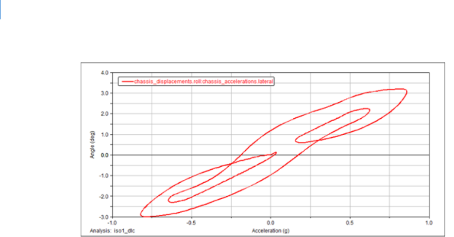
Getting Started Using Adams Car
Performing a Baseline ISO Lane-Change Analysis
132
Figure 6 Plot of Roll Angle versus Lateral Acceleration
Saving the Plot Configuration
Saving the plot configuration allows you to easily recreate the plots later in this tutorial after you modify the
full-vehicle assembly.
To save the plot configuration:
1. From the File menu, point to Export, and then select Plot Configuration File.
2. In the Configuration File Name text box, enter iso_lane_change.
3. Make sure All Plots is selected.
4. Select OK.
5. Return to Adams Car.
Modifying the Full-Vehicle Assembly
To change the roll angle versus lateral acceleration vehicle characteristic, modify the spring by creating and
assigning a new property file.
After you create a spring property file, assign the newly created property file to the front and rear springs.
To create a new spring property file:
1. From the Tools menu, select Curve Manager.

133
Full-Vehicle Analysis Tutorial
Performing a Baseline ISO Lane-Change Analysis
2. From the File menu, select New.
3. Verify that Type is set to spring.
4. Select OK.
Adams Car generates a plot of the force characteristic versus spring displacement in the plot window
of the Curve Manager.
5. In the Slope text box, enter 225.
6. Make sure the extension/compressions limits are set to
-100, 100.
7. Select Apply.
Adams Car modifies the spring characteristic.
8. In the Free Length text box, enter 300.
9. Select Apply.
10. From the File menu, select Save.
11. In the File text box, enter my_spring.
12. Select OK.
13. Close the Curve Manager.

Getting Started Using Adams Car
Performing a Baseline ISO Lane-Change Analysis
134
Adams Car returns to the main window.
To modify the springs:
1. In the model, right-click the front spring, ns[lr]_ride_spring, and then select Modify.
The Modify Spring dialog box loads the spring parameters in the text boxes.
2. Right-click the Property File text box and, from your default writable database, select my_spring.spr.
3. Replace Installed Length with Preload.
4. Enter a Preload of 5500.
5. Select Apply.
Adams Car assigns the new property file to the spring.
6. Repeat Steps 1 through 4 for the rear springs.
7. Select OK.
Performing an Analysis on the Modified Full-Vehicle Assembly
To determine how the modifications to the suspension subsystem affected the behavior of the vehicle,
perform another double lane-change analysis.
To perform the analysis:
1. From the Simulate menu, point to Full-Vehicle Analysis, point to Course Events, and then select
Double Lane Change.
2. In the Output Prefix text box, enter iso2.
3. Select OK.
Comparing Analysis Results
You now create a plot to compare the analysis results from the baseline vehicle assembly with the analysis
results from the modified vehicle assembly.
In addition to the plots defined in the plotting configuration file, you will review the vehicle velocity. The
Driving Machine longitudinal controller acts on the throttle demand to maintain the vehicle at the desired
speed.
To compare the analysis results:
1. Launch Adams PostProcessor.
2. From the Plot menu, select Create Plots.
3. In the Analyses text box, enter the iso1.ilc and iso2.ilc analyses.
4. Right-click the Plot Configuration File text box, and search your private database for
iso_lane_change.plt.

135
Full-Vehicle Analysis Tutorial
Performing a Baseline ISO Lane-Change Analysis
5. Select Cross Plotting.
6. Select OK.
Adams PostProcessor displays a plot of the roll angle versus lateral acceleration.
The new spring property file has a linear stiffness of 225 N/mm versus the 125 N/mm of the original
spring files. A stiffer spring reduces the roll angle of the vehicle, effectively modifying the handling
behavior and the ride comfort of the vehicle.
To create a plot of the longitudinal velocity versus time:
1. Select the New Page tool.
2. From the Request list, select chassis_velocities.
3. From the Component list, select longitudinal.
4. Set the Independent Axis to Time.
5. Select Add Curves.
Adams PostProcessor displays the plot you just defined.

Getting Started Using Adams Car
Performing a Baseline ISO Lane-Change Analysis
136
