
U.S. Department
of Transportation
Federal Aviation
Administration
Advisory
Circular
Subject: Airport Terminal Planning
Date: 7/13/18
Initiated By: APP-400
AC No: 150/5360-13A
1 Purpose.
This advisory circular (AC) provides updated guidance on the process of planning airport passenger
terminal facilities. This update reflects changes that have occurred in the aviation industry and to
planning practices for airport passenger terminal facilities since the Federal Aviation Administration
(FAA) published AC 150/5360-13, Planning and Design Guidelines for Airport Terminal Facilities, and
AC 150/5360-9, Planning and Design Guidelines for Airport Terminal Facilities at Non-hub Locations.
2 Distribution.
This AC is available on the FAA Office of Airports website.
3 Cancellation.
This AC cancels:
AC 150/5360-13, Planning and Design Guidelines for Airport Terminal Facilities, dated April
22, 1988; and
AC 150/5360-9, Planning and Design Guidelines for Airport Terminal Facilities at Non-hub
Locations, dated April 4, 1980.
4 Application.
This AC is a reference document and starting point for anyone planning airport passenger terminal
facilities, during or after the master planning process. For more detailed information, there are
references to relevant ACs, FAA orders, and industry guidance. For information on Airport
Improvement Program (AIP) or Passenger Facility Charge (PFC) eligibility and justification, refer to
FAA Order 5100.38, Airport Improvement Program Handbook, and FAA Order 5500.1, Passenger
Facility Charge Handbook.

7/13/18 AC 150/5360-13A
ii
5 Principal Changes.
This AC:
1. Combines ACs 150/5360-13 and AC 150/5360-9.
2. Changes the title of the AC from Planning and Design Guidelines for Airport Terminal
Facilities to Airport Terminal Planning.
3. Adds initial planning considerations before and during the terminal planning process.
4. Articulates a basic terminal planning process and key considerations for each step.
5. Provides a responsibilities matrix to clarify and streamline key coordination points
between the airport owner/operator, airport consultant, and FAA.
6. Incorporates information on integrating sustainability into the planning process, and a
chapter on the fundamentals of sustainability in terminal planning and design.
7. Includes references to relevant ACs, FAA orders, and other industry guidance and
resources on terminal planning.
8. Incorporates requirements to provide Service Animal Relief Areas (SARA) in airport
passenger terminals (Per 49 CFR § 27.71(h) and AC 5360-14, Access to Airports by
Individuals with Disabilities.
6 Feedback on this AC.
If you have suggestions for improving this AC, please use the Advisory Circular Feedback form at the
end of the document.
Elliott Black
Director, Office of Airport Planning and Programming
7/13/18 AC 150/5360-13A
iii
CONTENTS
Item Page
CHAPTER 1. USE OF THE ADVISORY CIRCULAR ..................................................................... 1-1
1.1 Intended Audience. ................................................................................................................... 1-1
1.2 Organization and Use of this Advisory Circular (AC). ................................................................ 1-1
1.3 Use of this Advisory Circular and Financial Assistance. ............................................................. 1-2
1.4 FAA Role in Passenger Terminal Planning. ................................................................................ 1-2
1.5 Use of Other Industry Publications. ........................................................................................... 1-2
CHAPTER 2. INITIAL PLANNING CONSIDERATIONS ............................................................... 2-1
2.1 General. ..................................................................................................................................... 2-1
2.2 Situation Assessment and Strategic Planning............................................................................ 2-1
2.3 Establishing Goals and Objectives. ............................................................................................ 2-2
2.4 Airport Master Plans. ................................................................................................................. 2-2
2.5 Other Factors for Initial Consideration. ..................................................................................... 2-3
2.6 Terminal Planning Study Design. ............................................................................................... 2-4
CHAPTER 3. TERMINAL PLANNING PROCESS ....................................................................... 3-1
3.1 General. ..................................................................................................................................... 3-1
3.2 Typical Terminal Planning Process............................................................................................. 3-1
3.3 Documentation. ....................................................................................................................... 3-10
CHAPTER 4. PLANNING METHODOLOGIES AND TOOLS ........................................................ 4-1
4.1 General. ..................................................................................................................................... 4-1
4.2 Demand Characteristics. ............................................................................................................ 4-1
4.3 Analytical Tools. ......................................................................................................................... 4-4
CHAPTER 5. TERMINAL BUILDING SPACE PROGRAMMING .................................................. 5-1
5.1 General. ..................................................................................................................................... 5-1
5.2 Level of Service. ......................................................................................................................... 5-1
5.3 Gross Terminal Area Estimates. ................................................................................................. 5-1
5.4 Terminal Building Space Allocation. .......................................................................................... 5-2
5.5 Trends and Innovations. .......................................................................................................... 5-15
CHAPTER 6. FUNCTIONAL RELATIONSHIPS AND TERMINAL CONFIGURATION ...................... 6-1
6.1 General. ..................................................................................................................................... 6-1
6.2 Origin and Destination Versus Hub/Connecting Airport Terminals. ......................................... 6-1
6.3 Terminal Components and Functional Relationships. ............................................................... 6-1
6.4 Terminal Siting Considerations. ................................................................................................. 6-5
6.5 Terminal Configurations. ........................................................................................................... 6-9
CHAPTER 7. TERMINAL APRON AREAS ................................................................................ 7-1
7.1 General. ..................................................................................................................................... 7-1
7.2 Aircraft Parking Gates. ............................................................................................................... 7-2
7.3 Aircraft Parking Gate Requirements. ......................................................................................... 7-3
7/13/18 AC 150/5360-13A
iv
7.4 Taxilanes and Aprons. ................................................................................................................ 7-7
7.5 Apron Lighting. .......................................................................................................................... 7-8
CHAPTER 8. AIRPORT GROUND ACCESS AND CIRCULATION ................................................. 8-1
8.1 General. ..................................................................................................................................... 8-1
8.2 Planning Studies. ....................................................................................................................... 8-1
8.3 Key Roadway and Parking Components. ................................................................................... 8-1
8.4 Roadways. .................................................................................................................................. 8-3
8.5 Terminal Curbside. ..................................................................................................................... 8-5
8.6 Parking Facilities. ....................................................................................................................... 8-7
8.7 Public Transit and Automated People Movers. ......................................................................... 8-9
8.8 Landside Signage and Wayfinding. .......................................................................................... 8-11
CHAPTER 9. SUSTAINABILITY IN TERMINAL PLANNING ........................................................ 9-1
9.1 General. ..................................................................................................................................... 9-1
9.2 Airport Sustainability Practice. .................................................................................................. 9-1
9.3 Airport Sustainability Planning. ................................................................................................. 9-4
9.4 Sustainability in Terminal Development.................................................................................... 9-5
9.5 Other Sustainability Considerations. ....................................................................................... 9-12
APPENDIX A. LIST OF ACRONYMS ....................................................................................... A-1
APPENDIX B. RESPONSIBILITIES MATRIX ............................................................................. B-1
APPENDIX C. REFERENCE MATERIALS .................................................................................. C-1
7/13/18 AC 150/5360-13A
1-1
CHAPTER 1. USE OF THE ADVISORY CIRCULAR
1.1 Intended Audience.
This document provides guidance for anyone initiating the planning and design of an airport
passenger terminal facility, including (but not limited to) the following:
Airport operators
Airport leadership
Airport planning staff
Airport engineering staff
Airline representatives
FAA personnel
Public stakeholders
Consultants
Airport planners
Terminal planners
Architects
Engineers
1.2 Organization and Use of this Advisory Circular (AC).
1.2.1 The nine chapters in this AC are presented in 3 main parts:
1. Initial Planning Considerations (Chapter 2) – Identifies key topics to consider before any
terminal planning project.
2. Terminal Planning Process (Chapter 3) – Articulates an approach to the planning process
with an emphasis on flexibility.
3. Terminal Planning Methodologies and Tools (Chapters 4 through 9)
a. Covers the three main functional elements of the terminal area (terminal building,
terminal apron, terminal landside).
b. Provides considerations, applicable reference documents, and tools for each element.
c. Discusses sustainability in terminal planning and design.
1.2.2 Using the terminal planning process presented in the following chapters, this AC gives the user
a basic explanation of each key subject and functional area, then refers the user to more
detailed resources.
1.2.3 It should be noted that this document combines AC 150/5360-13, Planning and Design
Guidelines for Airport Terminal Facilities, and AC 150/5360-9, Planning and Design Guidelines
for Airport Terminal Facilities at Non-hub Locations. The planning processes for hub and non-
hub terminal facilities planning were found to be generally comparable and not warranting
two separate discussions.

7/13/18 AC 150/5360-13A
1-2
1.3 Use of this Advisory Circular and Financial Assistance.
This AC provides general guidance to assist end users with the process of planning terminal
facilities. The material in this AC is independent from guidance on Airport Improvement
Program (AIP) or Passenger Facility Charge (PFC) eligibility and justification. Use of this AC
does not establish or ensure project eligibility or justification for AIP or PFC funding. For
information on AIP or PFC eligibility and justification, refer to FAA Order 5100.38, Airport
Improvement Program Handbook (Appendix N) and FAA Order 5500.1, Passenger Facility
Charge Handbook.
1.4 FAA Role in Passenger Terminal Planning.
1.4.1 For airports in the National Plan of Integrated Airport Systems (NPIAS), early coordination with
their local FAA Office of Airports Regional or Airports District Office is essential to facilitate
review and coordination of proposed airport development (particularly if seeking financial
assistance). In all cases, the FAA is involved to ensure that proposed airport development is
safe, efficient, and sustainable, is reasonable, meets airport design standards, and follows
environmental policy.
1.4.2 A responsibilities matrix is included in Appendix B to assist end users with the process of
planning terminal facilities. The matrix identifies when FAA coordination and approval are
required. For additional information, please coordinate with FAA Office of Airports Regional
or Airports District Office staff.
1.5 Use of Other Industry Publications.
1.5.1 The focus of this AC is the process of planning airport passenger terminal facilities. It is also
intended to be a starting point and reference document. There are other publications that
provide greater detail on the quantitative elements of terminal planning and design for each
respective discipline encountered within the terminal area. To avoid duplicative guidance and
recognize the natural evolution of terminal planning practices, this AC provides references to
other relevant resources. They can be found in the following sections and are summarized in
Appendix C, Reference Materials.
1.5.2 Please note that the FAA has included external reference materials that are widely used in the
airport industry. Some of these documents are proprietary and may require a subscription or
payment to access. The FAA is only including these documents because they are commonly
used references for terminal planning. The FAA is not endorsing any of these materials.
7/13/18 AC 150/5360-13A
2-1
CHAPTER 2. INITIAL PLANNING CONSIDERATIONS
2.1 General.
This chapter discusses key considerations before and during the formal terminal planning
process. Particular emphasis should be placed on this early stage of the planning process
because its outcome will form the scope of work for the project, and the foundation for the
rest of the terminal planning process.
2.2 Situation Assessment and Strategic Planning.
2.2.1 Before beginning the terminal planning process, airport operators should conduct a situation
assessment to identify problems at the existing terminal facility (if applicable) and decide
which problems the terminal project will address. A situation assessment can include
answering the following questions:
What problem(s) needs to be solved in the existing terminal facility?
Has the existing terminal infrastructure (or components thereof) reached the end of its
useful life?
Does the overall terminal complex (or any of its individual components) no longer meet
current or evolving operational needs of the airport?
o Does it require renovation, expansion, or replacement?
o Is the terminal complex (or any of its components) simply too small or large to
accommodate current or projected demand?
o Are there changes or expected changes in the operational fleet, or to airline tenants?
o Does the terminal need modernization or aesthetic improvements to meet changing
user and community expectations?
What sustainability initiatives, practices, or measures are required to ensure the new,
modernized or renovated terminal is sustainable?
What specific passenger or tenant complaints about the facility need to be addressed?
Are there multiple problems representing a combination of the above?
Has the terminal facility (or any of its components) suffered significant damage or closed
due to storms, electrical outages, flooding, or other external factors?
Have previous planning studies (e.g. an Airport Master Plan or related planning study)
explored the questions above or identified terminal related projects?
Are any environmental impacts anticipated as part of the project?
2.2.2 Documentation and communication of the outcomes of the situation assessment are
important parts of the planning process. The documented outcome of this step will define the
goals and objectives, and establish consensus among stakeholders and others who will play an
integral role in the planning process.

7/13/18 AC 150/5360-13A
2-2
2.3 Establishing Goals and Objectives.
2.3.1 Once the situation assessment is completed, it is important to have a clear understanding of
the goals and objectives of the terminal planning project in order to address the appropriate
problems and issues. This should occur at the onset of the planning process. The goals and
objectives should define the purpose of the terminal project and be prioritized to align with:
The airport operator’s overall vision and mission for the terminal facility and airport
enterprise;
The airport operator’s funding capabilities;
The motivations and needs of primary stakeholders, such as governmental leadership,
tenant(s), and users of the facility, and;
Airport sustainability practices.
2.3.2 Planners and designers should clearly state this vision in a written set of goals and objectives.
Stating goals and objectives also provides an early coordination opportunity for stakeholders
and others to agree that the project is needed, and provides a benchmark for evaluating
alternatives. Evaluation criteria for the project should relate to, or draw from, the established
goals and objectives.
2.3.3 Planners and designers, in coordination with environmental and other professionals, should
ensure that the goals and objectives are stated in a manner that supports subsequent phases
of the approval process. For example, projects being analyzed in accordance with the
National Environmental Policy Act (NEPA) require a supportable “purpose and need
statement.” This statement articulates what a proponent hopes to achieve and why the
project is necessary. NEPA analyses also require criteria that will be used to screen out
alternatives that do not achieve the project’s purpose and need. For additional information
on NEPA purpose and need statements and alternatives analysis, see FAA Order 5050.4,
National Environmental Policy Act (NEPA) Implementing Instructions for Airport Actions.
2.4 Airport Master Plans.
2.4.1 Airport master plans are studies that document and support the long-term development and
use of an airport’s land and facilities. Master plans provide the framework for future airport
development that will sustainably satisfy aviation demand in a cost-effective manner, and
balance capacity of airport functions while considering potential safety, environmental, and
socioeconomic impacts. AC 150/5070-6, Airport Master Plans, provides comprehensive
guidance on this topic.
2.4.2 In general, an airport master plan should establish the context for more detailed terminal
planning. In most cases, the terminal planning process should align with the broader
framework and guidelines of the airport master plan.
2.4.3 Airport master plans usually contain basic information useful to the terminal planning process.
This includes an inventory of existing airport facilities, aviation activity forecasts, capacity
analyses, estimates of facility requirements, sustainability initiatives, environmental

7/13/18 AC 150/5360-13A
2-3
considerations, an airport layout plan set, and information on land use, terminal area, and
intermodal surface access.
2.4.4 The terminal facility analysis contained in an airport master plan is usually limited to layouts
and drawings delineating general location, overall area, and basic configuration of the
terminal area development envelope. However, some airport operators develop master plans
with a strong emphasis on terminal planning and may provide more detailed documentation
on this subject.
2.5 Other Factors for Initial Consideration.
Following are additional factors that contribute to a successful airport passenger terminal
planning process.
2.5.1 Project Team.
In the initial phase of the planning process, an airport should assemble a project team that will
function for the duration of the planning process. This team typically includes the lead person
for the planning effort for both the airport and the planning consultant team, and their key
team members. The airport may or may not include stakeholders outside of airport staff on
the project team. However, FAA encourages stakeholder involvement early in the planning
process. Examples of key stakeholders include airlines, airport tenants, the consultant team,
FAA (e.g., the Office of Airports and Air Traffic), other federal agencies such as the
Transportation Security Administration (TSA), Department of Homeland Security (DHS), and
Customs and Border Protection (CBP), other regulatory stakeholders, local government, local
business groups, and community planning groups.
2.5.2 Consultant Selection.
Airport operators typically hire a consultant to assist with passenger terminal planning
studies. As a general rule, consultants provide subject matter expertise and additional labor
to complete tasks within a given schedule. For information on the selection and engagement
of architectural, engineering, and planning consultants, see AC 150/5100-14, Architectural,
Engineering and Planning Consultant Services for Airport Grant Projects. Another useful
reference is the Airport Consultants Council Contracting Toolkit.
2.5.3 Financial Considerations.
2.5.3.1 Airports must address a number of financial considerations early in the planning
process. For example, airport operators should have a realistic sense of their
funding capacity, as this is a key to determining what is affordable or feasible.
The airport should give early consideration to overall capital costs and potential
funding sources; annual debt service (if any portion of the funding is to come
from bond proceeds); resulting operating and maintenance costs; forecast activity
levels in terms of passengers and operations; ability to generate non-aeronautical
revenue; cost recovery options; and facility management plans (including the plan
for airline rates and charges). All of these factors should be considered when
evaluating the financial feasibility of each option under consideration.

7/13/18 AC 150/5360-13A
2-4
2.5.3.2 As stated earlier, neither this AC nor the use of this AC establishes project
eligibility or justification for AIP or PFC funding. For information on AIP project
eligibility and justification, please refer to FAA Order 5100.38, Airport
Improvement Program Handbook. For information on the PFC program, please
refer to the FAA Order 5500.1, Passenger Facility Charge Handbook.
2.5.4 Environmental Considerations.
Early in the terminal planning process, airports should understand the level of environmental
review that will be required for the project and potential projects emerging from the study.
Underestimating the level of review (or assuming that no review is required) can have
significant impacts on the trajectory of a project. Planners and environmental specialists
should attempt to identify key environmental issues for the proposed project to ensure the
planning project scope and budget provide enough resources to analyze them, there is
enough analysis and documentation for any environmental review, and the overall schedule
accounts for the time required to complete this review. For comprehensive information on
NEPA requirements, see FAA Order 5050.4, National Environmental Policy Act (NEPA)
Implementing Instructions for Airport Actions. For additional perspective on environmental
considerations in the comparable context of master planning, see the Environmental
Considerations chapter in AC 150/5070-6, Airport Master Plans. For airports in the NPIAS,
operators should also coordinate with their local FAA Regional or Airports District Office for
information on environmental review requirements.
2.6 Terminal Planning Study Design.
A key output of these initial efforts should be a scope of work that is tailored to the project.
The scope of work will articulate the types of analyses and level of effort needed to address
key issues. For airports in the NPIAS, airport operators should coordinate with their local FAA
Regional or Airports District Office to discuss the project, timeframe, basis for the project, key
assumptions (e.g. the forecast of aviation activity used to define facility requirements), level of
effort, NEPA considerations, and ultimately, to tailor the scope of the effort. The airport
operator should develop a scope of work that is appropriate for the circumstances, and will
achieve the identified goals and objectives.

7/13/18 AC 150/5360-13A
3-1
CHAPTER 3. TERMINAL PLANNING PROCESS
3.1 General.
This chapter describes a typical terminal planning process with an emphasis on flexibility and
adaptation. This approach commences following the completion of steps identified in Chapter
2 and the development of a scope of work. The output of this planning process is typically a
report that documents each step in the process, and the final recommendations on the
terminal project.
3.2 Typical Terminal Planning Process.
Figure 3-1 depicts a typical terminal planning process. The following sections describe each
step in this process diagram, and key considerations.
Figure 3-1 Conceptual Terminal Planning Process
3.2.1 Initial Planning Considerations.
As discussed in Chapter 2 and depicted in Figure 3-1, an airport operator should complete a
number of initial steps before formally initiating the terminal planning process. These steps
include assessing the situation and identifying problems to be resolved, establishing goals and
objectives, forming the project team, and developing a scope of work.
3.2.2 Stakeholder Involvement.
3.2.2.1 The process of planning an airport passenger terminal requires considerable
coordination and input from a number of airport users, and other interested
parties. Participants in such a process may include, but are not limited to:
Airport management and staff from key departments (landside/airside
operations, finance, commercial development, airport fire department/local
fire department/airport emergency response staff, airport police, etc.), as
well as other airport departments and offices (environment/sustainability,
etc.), which can provide valuable perspective and project support.

7/13/18 AC 150/5360-13A
3-2
Tenant airlines, concessionaires, and other service providers and tenants.
The terminal planning consultant, and other consultants indirectly involved or
working on other aspects of the facility.
FAA.
Other federal agencies such as the TSA, DHS, and CBP.
Relevant local governmental agencies, municipal planning offices,
transportation departments, local business groups, community planning
groups, etc.
3.2.2.2 Stakeholder involvement runs parallel to the planning process presented in this
chapter. Airport operators should engage stakeholders - or the project advisory
committee if an airport chooses to form one - to review terminal planning
information and provide input at key project milestones. Airport operators
should also engage the general public as part of the planning process. For specific
information on public participation, see AC 150/5050-4, Citizen Participation in
Airport Planning.
3.2.3 Existing Conditions.
3.2.3.1 A foundational step in the planning process is the documentation of existing
conditions (also called an inventory). “Existing conditions” refers to the physical
characteristics of the facility by functional element, as well as non-physical
elements like operational activity and the current critical aircraft. For information
and guidance on critical aircraft, see AC 150/5000-17, Critical Aircraft and Regular
Use Determination.
3.2.3.2 The airport owner/operator or consultant (if applicable) conducting the study
should assemble a base set of plans, documents, and photos to document existing
conditions that are relevant to the terminal planning project and key issues
identified in the situation assessment. When the project is terminal replacement
or enhancement, the airport owner/operator or consultant should evaluate the
physical characteristics of the existing facility. This process includes a walk-
through of the facility and reviewing the most recent Airport Layout Plan (ALP),
airport master plan, related internal and external planning studies, and all existing
conditions documents the airport has on file related to terminal facilities (e.g.,
electronic drawings of terminal plans, site surveys, utility drawings, and property
maps).
3.2.3.3 Additionally, the airport owner/operator or consultant should gather any relevant
operational data on functional elements in the terminal complex to document
demand levels, processing rates, and any other applicable data. A wide range of
data (passenger enplanements, aircraft operations, delay statistics, etc.) are
available from the FAA Operations and Performance Data website. Among the
available data, the FAA Terminal Area Forecast (TAF) provides aviation data users
with historical and forecast statistics on passenger demand and aviation activity
at U.S. airports. For the purposes of documenting existing conditions, historical

7/13/18 AC 150/5360-13A
3-3
data are summarized by year for each facility. The TAF databases are available in
zipped .dbf format through the “Download Data” links on the TAF website.
3.2.3.4 The airport owner/operator or consultant should document any deficiencies in
information and reach consensus with the airport owner/operator on how to
address them (e.g., will additional work be necessary to obtain basic data, or can
assumptions be made to form the basis of the planning effort). Throughout the
planning process, the airport owner/operator or consultant should document all
assumptions and their underlying rationales.
3.2.4 Forecasts of Aviation Activity.
3.2.4.1 The forecast of aviation activity is a pivotal step in the terminal planning process.
Aviation activity forecasts are estimates of demand expressed in passenger
activity levels (enplanements and total passengers) and aircraft operations
(including the forecast critical aircraft). Forecasts are completed during the
master planning process or as part of a more focused terminal planning study.
These projections are used to determine and substantiate the extent and type of
development needed to accommodate expected traffic (i.e., facility
requirements).
3.2.4.2 If the airport owner/operator is preparing a standalone terminal planning study
or Terminal Area Narrative Report, and anticipates seeking federal financial
assistance for any portion of terminal construction, the airport owner/operator
must present a forecast of aviation activity. The local FAA Regional or Airports
District Office must approve the forecast in these instances.
3.2.4.3 The forecast may be developed for the study’s planning period or be from a
recent planning effort (i.e., a recent Airport Master Plan) if no significant changes
to the forecast or its assumptions have occurred since that effort. For additional
information, see the section on forecasts for planning or environmental projects
in FAA Order 5100.38, Airport Improvement Program Handbook.
3.2.5 Facility Requirements.
3.2.5.1 Facility requirements translate the output from forecasts of aviation activity into
requirements and programmatic input (or sizing) for the functional components
of the terminal facility. Facility requirements and other planning
recommendations should be linked to activity milestones (or triggers) defined in
terms of planning activity levels. The connection to activity levels enables capital
improvements to be accelerated or delayed as actual activity dictates. It is critical
to view the planning process as dynamic and consider potential changes in the
aviation industry (e.g., aircraft fleet mix, technology, airport and airline business
models, and passenger needs). Flexibility to adapt to changing aviation industry
conditions and the economy is one of the most important considerations in
terminal planning efforts.
3.2.5.2 See Chapter 5, Terminal Building Space Programming, for an overview of terminal
building space programming and key factors that drive the programming of major

7/13/18 AC 150/5360-13A
3-4
terminal components. The functional relationships between terminal
components are described in Chapter 6, Functional Relationships and Terminal
Configuration.
3.2.5.3 At the conclusion of the Forecast and Facility Requirements steps, it is critical for
the airport owner/operator to establish consensus about the outcome and
resulting recommendations with the project team and advisory committee before
proceeding with the development of terminal alternatives.
3.2.6 Terminal Alternatives Development and Evaluation.
The following sections describe methods for evaluating and selecting a preferred passenger
terminal alternative.
3.2.6.1 Development and Evaluation of Initial Alternatives.
3.2.6.1.1 The investigation of terminal alternatives should include a high-level
consideration of different terminal alternatives to accommodate forecast activity
levels and resulting facility requirements (see Chapter 6, Functional Relationships
and Terminal Configuration). The purpose of this step is to identify the full range
of potential options, rather than explore alternatives in detail. For comparison,
alternatives should be developed using consistent criteria including, but not
limited to, aircraft fleet mix and wingtip spacing, terminal and concourse
dimensions to meet gate requirements, relationship to the airfield, roadway
network, and other support facilities, and sustainability considerations. Each
alternative should be accompanied by a brief summary of the main points of
consideration related to it. Alternatives at this stage in the planning process may
be developed using criteria which could be revisited later and modified based
upon input and discussions with stakeholders. Figure 3-2 shows a variety of
common conceptual terminal redevelopment alternatives.

7/13/18 AC 150/5360-13A
3-5
Figure 3-2 Example of Initial Conceptual Terminal Alternatives
3.2.6.1.2 Airports can use the following three-step process to compare the alternatives,
and reduce the number of possible alternatives to a shortlist of alternatives
warranting further refinement and evaluation:
1. Identify Evaluation Criteria. Develop evaluation criteria that represent the
essential factors to consider when determining the preferred development
alternative(s) for the airport. The criteria and definitions should be carefully
tailored to match the goals, objectives, and other parameters established
earlier in the project. Initial criteria may include economic viability, airside
access, expansion flexibility, walking distances, landside access availability,
operational flexibility, site availability, airspace impacts, Airport Traffic
Control Tower (ATCT) line-of-sight, environmental issues, constructability,
schedule, and order-of-magnitude costs.
2. Establish Weighting (if needed). Weighting factors may be assigned to each
evaluation criterion according to relative importance. Airports should
develop the weighting with input from stakeholders, and consider priorities
in relation to goals and objectives identified earlier in the planning process.
3. Perform a Technical Ranking. Develop a matrix or other framework for
ranking the alternatives against each criterion. The ranking should represent
majority consensus among stakeholders. One possible ranking scheme
utilizes rankings of positive, neutral, or negative for each criterion.
3.2.6.1.3 The score for each alternative is the sum of all factors identified for the criteria
listed. This preliminary evaluation process can be repeated with second-tier

7/13/18 AC 150/5360-13A
3-6
criteria in order to reduce a large number of potential alternatives to a more
manageable number.
3.2.6.1.4 An evaluation matrix which includes generalized evaluation criteria and
definitions used in the preliminary evaluation process is presented in Figure 3-3.
In the example provided, positive, neutral, and negative rankings are notionally
indicated by +, 0, and - rankings, respectively.
Figure 3-3 Example Preliminary Evaluation Matrix
3.2.6.2 Shortlisted Alternatives.
3.2.6.2.1 Following identification of shortlisted terminal alternatives, the conceptual
terminal plans should be redrawn at a larger scale (greater level of detail) and
depict specific functional areas shown. This will allow for a more detailed
evaluation of each alternative. See Figure 3-4 for examples of typical conceptual
alternatives. This refinement is prudent because it:
Ensures each alternative conforms to the goals and objectives.

7/13/18 AC 150/5360-13A
3-7
Closely examines the ability of each alternative to satisfy demand, and the
functional and operational requirements of airlines, passengers, tenants,
automobiles, and other elements.
Ensures each alternative can be phased without causing significant disruption
to airport operations.
Allows for the preparation of order-of-magnitude costs and financial
feasibility assessments of each alternative.
3.2.6.2.2 The airport owner/operator or consultant should write brief narrative
descriptions of each shortlisted terminal concept (and potential variations).
Figure 3-4 Examples of Prototypical Shortlisted Terminal Alternatives
Note: Conceptual drawings are shown for thematic purposes. Not to scale.
3.2.6.3 Refined Evaluation.
3.2.6.3.1 For each of the shortlisted terminal alternatives that are developed in greater
detail, the initial evaluation criteria should be revisited and reassembled in a new
matrix (potentially with new or refined criteria) to complete the evaluation. A
scoring system may be used in this secondary alternative evaluation. The system
could be simple (such as assigning positive, neutral, or negative (+, 0, -) labels to
each alternative based on specific criteria) or more elaborate (such as allocating
points to each alternative based on the criteria). Figure 3-5 shows an example of
a secondary evaluation matrix.

7/13/18 AC 150/5360-13A
3-8
Figure 3-5 Example Secondary Evaluation Matrix
3.2.6.3.2 The result of the evaluation process should be presented graphically so the
recommended development alternative, phasing, schedule, and other key details
can be readily understood. This is particularly important if the recommended
approach combines different elements of the shortlisted alternatives.
3.2.6.4 Financial Feasibility.
Using rough order of magnitude (ROM) cost estimates, the planning team should
considerer financial planning factors to confirm the economic viability of terminal
alternatives. An analysis of the financial feasibility of each investigated alternative
in parallel with alternatives development and evaluation is a key factor in
selecting the preferred alternative. As part of the evaluation process, a second
round of financial feasibility should occur once the airport selects a preferred
alternative.
3.2.6.5 Preferred Terminal Development Alternative.
3.2.6.5.1 Once the airport owner/operator identifies the preferred terminal development
alternative, the layout should be clearly depicted in plans, cross-sections,
perspectives, and descriptive narrative. This delineation should also address the
original planning parameters, site constraints, and other criteria set out at the
beginning of the study. A narrative prepared for the preferred terminal

7/13/18 AC 150/5360-13A
3-9
alternative should describe the alternative development and evaluation process,
the resulting recommendation, and cover major points. These include:
Achieving balanced capacities (e.g., the passenger curbfront should support
the number of passengers that the aircraft gates can accommodate).
Overall flexibility of space within the terminal building.
Revenue enhancement opportunities.
Operational flexibility for airlines and concessionaires.
Flexibility to adapt to industry changes and future considerations.
Ease of ground transportation access.
Phasing of terminal improvements.
3.2.6.5.2 The implementation of the preferred terminal alternative may need to be a multi-
phased development extending over a significant period of time. A multi-phased
approach may be necessary for several important reasons, including, but not
limited to:
The need to complete enabling projects.
The need to retain a minimum number of operational aircraft gates at all
times during construction.
The need to maintain existing terminal building systems and equipment in
operation during all phases.
The potential requirement to build a substantial portion of the new terminal
on the same site as the existing terminal.
The need to preserve the safety of passengers, vehicles, personnel, and
aircraft during all phases of construction.
Other factors related to cost, affordability, climate, and seasonal construction
variables.
3.2.6.5.3 Finally, there are a number of elements which will continue to be evaluated as
the planning evolves and projects move into design phase (e.g., plans for baggage
processing, concessions, passenger processing, concourse phasing, aircraft
parking, and departure holdrooms).
3.2.7 Recommended Plan.
3.2.7.1 Utilizing the preferred development alternative, this step in the process
summarizes all of the proposed development at a high level. The outcome of this
step is a chapter in the planning document that presents the airport’s
development plan for the planning horizon. This plan is the precursor to post-
planning processes (implementation) where individual projects undergo more
detailed review and development towards project implementation. This is
important to remember throughout the planning process.

7/13/18 AC 150/5360-13A
3-10
3.2.7.2 This chapter in the report typically includes:
A supporting narrative that summarizes all the project recommendations.
A graphic that overlays the proposed development on a single scale graphic of
the airport (typically in the form of linework overlaid on an aerial or vector
base).
A tabular summary of proposed development with development triggers
identified (levels of activity, facility condition, phasing, etc.).
A tabular program (if seeking federal financial assistance) of the proposed
terminal development that quantifies the main functional program elements,
and delineates public-use area verses non-public use areas. For the
applicable definition of public-use area, please refer to FAA Order 5100.38,
Airport Improvement Program Handbook.
Capital Improvement Plan.
An updated ALP set.
3.3 Documentation.
Clear and concise documentation is critical to the success of the overall planning process, and
ultimately to the successful transition to design and implementation phases. The outcome of
the entire planning process is the project documentation, which is prepared in parallel with
the terminal planning process steps.
3.3.1 Document Organization.
Terminal planning documents are typically organized around the fundamental process steps
discussed in this chapter, but also include introduction and recommended plan sections.
Below is an example of chapters that are typically included. This is similar to the organization
of a typical master plan document. See AC 150/5070-6, Airport Master Plans, Chapter 2, for
additional information and coordinate the final document organization with FAA Regional or
Airports District Office staff.
1. Introduction
2. Existing conditions
3. Forecasts of aviation activity
4. Facility requirements
5. Alternatives development and evaluation
6. Recommended plan

7/13/18 AC 150/5360-13A
4-1
CHAPTER 4. PLANNING METHODOLOGIES AND TOOLS
4.1 General.
4.1.1 This chapter discusses methods and tools to support the terminal planning process, including
demand characteristics and analytical tools.
4.1.2 Demand levels and characteristics provide basic data necessary for terminal planning or
design. Therefore, they are usually researched and established early in the planning process.
Analytical tools are used later in the planning process to determine terminal facility needs and
sizing.
4.2 Demand Characteristics.
Demand forecasts estimate future passenger activity and aircraft operations levels.
Preparation of annual activity data and the conversion of demand forecasts into planning
activity levels are addressed in Chapter 3, Terminal Planning Process. Facility requirements
and other terminal space programs should be linked to annual “activity milestones” that are
defined in terms of planning activity levels rather than future calendar years. Airport
owners/operators or consultants develop terminal space programs based on peak demand
levels (e.g., busiest day of the year, Peak Hour of the Average Day of the Peak Month). The
following sections describe basic activity characteristics and traditional methodologies to
determine those characteristics.
4.2.1 Annual Activity.
4.2.1.1 Use annual activity to determine order-of-magnitude facility requirements.
Annual forecast data relevant to the terminal planning process includes:
Passenger enplanements – the annual number of departing passengers using
a terminal facility. Enplanements can be subcategorized by domestic and
international, originating or connecting, or any other category depending on
project need. Annual enplanements can be used to derive design period
enplanements needed to develop order-of-magnitude facility requirements.
Passenger deplanements – the annual number of arriving passengers using a
terminal facility. Deplanements can be subcategorized by domestic and
international, terminating or connecting, or other categories depending on
the project need. Annual deplanements can be used to derive design period
deplanements needed to develop order-of-magnitude facility requirements.
Aircraft operations – the annual number of arriving and departing aircraft
that utilize the terminal facility. Aircraft operations can also be
subcategorized by domestic and international, and wide-body versus narrow-
body aircraft. Annual aircraft operations can be used to calculate order-of-
magnitude gate requirements.
Aircraft fleet mix – the specific types of aircraft serving an airport. Fleet mix
is important because different aircraft have different passenger capacities

7/13/18 AC 150/5360-13A
4-2
(i.e., number of seats). Aircraft fleet mix can be used to calculate order-of-
magnitude gate requirements and determine the flexibility of a proposed
aircraft parking layout.
Load factor – the percentage of seats utilized on an aircraft; this can be
determined and expressed individually for specific airlines or type of
operation (e.g., international or domestic), or as an average of all aircraft
operations at an airport.
4.2.1.2 Annual forecasts are typically translated to peak daily and hourly demand.
4.2.2 Peak Activity.
4.2.3 Peak activity measures the highest projected level of passenger or operational activity in peak
months, days, or hours. Terminal facility planning requires knowledge of peak activity
because the terminal space programs are based on projected peak volumes of passengers.
For example, the number of lanes required for a security screening checkpoint is based on the
maximum throughput of an individual screening lane. If there are 300 passengers in the peak
hour and each lane can process 150 passengers per hour, then a minimum of two screening
lanes are needed.
4.2.4 Chapter 5, Terminal Building Space Program, describes the relationship of peak activity to
building a space program for each terminal functional area. Depending on the level of analysis
required, peak activity data can be prepared for passenger enplanements and deplanements
(and associated sub classifications), and aircraft operations.
4.2.5 The following publications provide guidance on forecasting and peaking calculations:
FAA Guidelines, Forecasting Aviation Activity by Airport
Airport Cooperative Research Program (ACRP) Synthesis Report 2, Airport Aviation Activity
Forecasting
ACRP Report 82, Preparing Peak Period and Operational Profiles—Guidebook
4.2.6 Average Day of the Peak Month (ADPM) is a common methodology used to identify existing
and forecast future peak activity. The peak month is the month representing the highest
percentage of total annual activity. ADPM is determined by dividing the peak month’s activity
by the total number of days in that month. Future ADPM is determined by multiplying
forecast annual activity by the historic percentage of total activity in the peak month, and
again, dividing by the total number of days in that month. Figure 4-1 shows the method of
determining existing and forecast ADPM.

7/13/18 AC 150/5360-13A
4-3
Figure 4-1 Determination of Average Day Peak Month Activity
4.2.7 Design Day Flight Schedules.
4.2.7.1 Another method used to determine future peak activity is through the
development of a “design day” flight schedule. A design day flight schedule
differs from a calculated peak activity number derived from annual activity in that
it is based on a theoretical day, or rather, based on existing/current airline and
passenger characteristics, such as:
Airline flights – scheduled commercial aviation activity, by each airline.
Airline fleet mix – aircraft types used by each airline.
Airline load factors –percentages of seats occupied, per each airline flight.
Passenger type – percentage of passenger types such as families, business
travelers, leisure travelers, prescreened travelers, and passengers with airline
status.
4.2.7.2 An existing design day flight schedule provides a distribution of passengers on an
hourly basis throughout the design day. The peak hour can therefore be
identified as the hour in the schedule that includes the highest passenger
volumes for a given function, such as enplaning passengers, deplaning
passengers, connecting passengers, and international passengers.
4.2.7.3 Future peak hour volumes are determined by applying appropriate growth rates
to the existing design day flight schedule and increasing the activity levels to
match forecast demand. This can be accomplished via a combination of “up-
gauging” (utilizing larger aircraft with higher numbers of seats per plane) aircraft
types and the introduction of additional flights, depending on the strategies most
likely to be deployed by the individual airlines at the airport. Coordinate with air
carriers to validate and tailor assumptions used in the development of the future
schedule.

7/13/18 AC 150/5360-13A
4-4
4.2.7.4 Industry resources that provide additional information for determining annual
and peak activity include:
ACRP Report 23, Airport Passenger-Related Processing Rates
ACRP Report 25, Airport Passenger Terminal Planning and Design
ACRP Report 163, Guidebook for Preparing and Using Airport Design Day
Flight Schedules
4.3 Analytical Tools.
A variety of analytical tools are available to assist in developing a terminal building space
program. Three general levels of analysis – quick-estimation methods, macroscopic methods,
and microsimulation methods – can be used to generate requirements. Each of these
methods differs in terms of the level of effort to perform the analysis, the level of accuracy or
reliability of the results, and the required level of user expertise. The following sections
describe each method and when each should be applied.
4.3.1 Quick-Estimation Methods.
Quick-estimation methods are best applied in early, conceptual stages of planning. They are
used to develop a high-level terminal space program. A physical design is not needed at this
low level of detail. Typically, the outputs are presented in tabular form. These methods are
used as initial screening criteria to determine whether a terminal space program can be
accommodated within the allowable development area, and therefore, if further analysis is
warranted. The International Air Transport Association (IATA) Airport Development Reference
Manual contains rules-of-thumb for the following facilities: check-in, passport control,
centralized security check, gate area hold rooms, bag claim units, and arrival hall. ACRP
Report 25, Airport Passenger Terminal Planning and Design, Volume 1, also contains gross
area terminal planning factors. These factors are a useful tool when considering rough
terminal sizing.
4.3.2 Macroscopic Methods.
Macroscopic methods are used to understand overall passenger, baggage, and vehicular
flows. This level of analysis typically requires a design or concept that can be represented in a
model environment, along with logical assumptions assigned to passenger activities. Model
outputs can include renderings of the simulation including passenger routes, flows at
processing points, and numerical outputs. Macroscopic methods can be used to generate a
reasonable planning or design-level space program. These methods are fairly sophisticated,
but require less time and experience than microsimulation methods. Macroscopic methods
are most useful during a terminal planning conceptual design phase when developing a
comprehensive space program, as opposed to detailed focus on one specific functional area.
ACRP Report 25, Airport Passenger Terminal Planning and Design – Volume 2 Spreadsheet
Models and User’s Guide includes a spreadsheet model that is useful for this level of analysis,
covering many of the functional terminal components.
4.3.3 Microscopic Methods.
Microscopic methods use sophisticated computer software to simulate individual passenger,
baggage, and vehicle movements, and their interaction with each other. This method
7/13/18 AC 150/5360-13A
4-5
provides the most realistic passenger movement analysis and projects passenger interactions,
detailed queuing/movements, and other passenger characteristics and behaviors. Outputs
from this method include numerical outputs, three-dimensional visualization images, or
videos for use in presentations. Due to their complexity, microscopic methods require the
highest level of experience and maximum level of effort to produce results. These methods
are most useful when analyzing and demonstrating micro-operational improvements, such as
addressing security checkpoint congestion when it is impossible to expand beyond the
building envelope.
7/13/18 AC 150/5360-13A
4-6
PAGE INTENTIONALLY LEFT BLANK

7/13/18 AC 150/5360-13A
5-1
CHAPTER 5. TERMINAL BUILDING SPACE PROGRAMMING
5.1 General.
This chapter provides an overview of terminal building space programming. Programming
defines the overall terminal size and the size of individual terminal components necessary to
meet projected activity levels. Terminal space programs can be developed for a variety of
project types, ranging from high-level strategic plans to more detailed design of new or
expanded facilities.
5.2 Level of Service.
5.2.1 Level of Service (LOS) is defined as a qualitative and quantitative measurement of comfort
experienced by passengers using the airport passenger terminal facility. LOS is a balance, or
compromise, between customer service, cost, and available space. It is a key parameter to
address at the onset of the spatial programming process. LOS is traditionally rated on a scale
of A through F, excellent to unacceptable. This metric has evolved in recent years to simplify
the categories “optimum, sub-optimum, under-provided, and over-design” (IATA Airport
Development Reference Manual). Factors that are weighed to determine LOS vary by each
terminal element, but can include factors such as processing time, level of crowding, walking
distance, climate, etc.
5.2.2 Airport owners/operators are encouraged to design terminal projects to maintain a balanced
LOS that results in an optimal (neither overbuilt nor underbuilt) and practical facility for the
existing and planned activity levels.
5.2.3 Guidance on LOS can be found in the following resources:
ACRP Report 55, Passenger Level of Service and Spatial Planning for Airport Terminals
ACRP Report 25, Airport Passenger Terminal Planning and Design
IATA Airport Development Reference Manual
5.3 Gross Terminal Area Estimates.
5.3.1 Gross terminal area estimates are appropriate early in the planning process to determine
orders of magnitude and sizing of key terminal components. Estimating generalized, gross
terminal building sizes can be accomplished using the following methodologies:
Benchmarking other terminal facilities with similar functions, passenger activity levels, and
passenger demographics (e.g., a high percentage of international or connecting
passengers).
Calculating ratios based on demand and capacity (e.g., overall terminal area per required
units, such as gates and passengers).
5.3.2 Guidance for the above estimating techniques can be found in the following resources:
ACRP Report 25, Airport Passenger Terminal Planning and Design
IATA Airport Development Reference Manual

7/13/18 AC 150/5360-13A
5-2
5.4 Terminal Building Space Allocation.
5.4.1 A planning level terminal building space program should focus on the individual functional
areas and terminal components identified in Chapter 6, Functional Relationships and Terminal
Concepts. It is important to consider inputs from a variety of stakeholders, including airlines
and tenants, FAA (typically when receiving federal financial assistance), and other users.
5.4.2 The following sections describe major functional components, key variables, necessary inputs,
and industry-accepted resources involved in calculating space requirements.
5.4.3 Check-in Lobby.
5.4.3.1 The check-in lobby is historically where departing passengers check-in for a flight,
drop off checked baggage, and obtain boarding passes and other information for
the flight. Traditionally, check-in lobbies were designed to be grand public
spaces: the “front door” of an important public facility. Until around 2001, most
check-in lobbies were long, linear spaces with large areas reserved for airline
ticket counters, passenger queuing and waiting, airline ticket office space, and
supporting areas such as restrooms and concessions.
5.4.3.2 Technology and evolved security requirements have significantly changed the way
passengers and airlines use the check-in lobby. This has resulted in changes to
space requirements. First, self-service check-in and baggage drop kiosks allow
passengers to bypass the traditional check-in counters, and allow the check-in
process to take place anywhere inside or outside the terminal building (such as at
the curb or parking garage). In addition, computers and personal electronic
devices allow passengers to check-in off-airport. These passengers interact with
airline personnel only to drop off bags or to resolve problems. The result is a
significant change in passenger and airline approaches to the check-in process. As
the check-in process evolves, airline processes and airport policy are likely to
create more options for the traveler. These options may reduce the building
space allocated to the check-in lobby.
5.4.3.3 The primary components of the check-in lobby are:
Curbside check-in/baggage drop – a location outside of the terminal building,
typically along the departure curbside, where passengers can check-in and
drop baggage before entering the building.
Lobby check-in/baggage drop – a location inside the terminal building where
passengers can check-in and drop baggage, either at a self-serve kiosk or
traditional airline counter. The area can be a single consolidated space, or
divided into segments by function (e.g., for boarding passes only or traditional
check-in with an agent) or passenger classification (e.g., first class, economy,
etc.). Typically, this area also includes airline office space.
Passenger queuing – areas designated for passengers waiting to check-in or
check baggage, either at self-serve kiosks or traditional airline counters.

7/13/18 AC 150/5360-13A
5-3
Public circulation – open areas from the entry vestibules to the check-in
zones, and from the check-in zones to the security checkpoints that allow
passengers and others to efficiently move throughout the lobby. This area
also includes vertical circulation between levels and life safety egress.
Concessions –concessions space is warranted in the check-in lobby area to
provide access for basic needs such as food and beverages and news/gifts for
passengers who are delayed, have a long pre-security wait, or are spending
time with well-wishers not allowed beyond security. Concessions also
provide basic amenities to airport employees who do not have access to post-
security areas.
Support areas – areas allocated for support functions such as restrooms,
public seating, public information kiosks, and mechanical spaces.
5.4.3.4 Each airport and airline situation is different, but there are common variables
which influence spatial requirements for the check-in lobby.
Passenger volumes – estimated passenger volumes, typically expressed in
peak hour numbers, based on forecasted activity levels.
Patrons and passengers – factors such as the ratio between originating and
connecting passengers, the characteristics and requirements of passengers
who check-in and drop-off baggage (e.g., passengers requiring assistance, the
number of well-wishers who see passengers off, earliness arrival profiles,
etc.).
Processing rates objectives – acceptable processing rates, allowable wait
times, maximum queuing lengths, etc. to meet established level of service
parameters. Objectives need to be balanced against facility and equipment
capacities.
Airport environment – are check-in lobby facilities (ticket counters or kiosks)
for common use or preferential use? Is there a single dominant hub airline?
Or are there multiple airlines?
Airline processes – the unique characteristics, equipment, processes, and
special requirements of individual airline check-in and bag-drop policies.
5.4.3.5 Resources that provide in-depth explanations and tools to calculate check-in
lobby space requirements include:
ACRP Report 25, Airport Passenger Terminal Planning and Design
ARCP Report 55, Passenger Level of Service and Spatial Planning for Airport
Terminals
ACRP Report 10, Innovations for Airport Terminal Facilities
ACRP Report 23, Airport Passenger-Related Processing Rates
IATA Airport Development Reference Manual

7/13/18 AC 150/5360-13A
5-4
5.4.4 Outbound Baggage Processing.
5.4.5 Outbound baggage processing includes the area and equipment required to accommodate,
sort, screen, and process checked baggage from the check-in lobby to the aircraft. Outbound
baggage processing includes the following main components:
Baggage conveyance system – automated conveyor belts that sort and connect baggage
from the check-in/drop-off point to the baggage security screening machines, and from
the baggage screening machines to outbound baggage makeup devices.
Primary baggage screening area – the area that accommodates screening equipment
where all bags are initially inspected; cleared bags proceed to outbound baggage make-up
devices, and “alarmed” bags (e.g., bags that are determined to contain suspicious
contents) are either rescreened or sent to secondary screening.
Secondary baggage screening area – the area that accommodates screening equipment
where alarmed bags are manually screened a second time.
Outbound baggage devices – automated devices that circulate and sort cleared baggage in
preparation to be transported to the aircraft. These devices range from simple flat-plate
to sloped plate units.
Staff support areas – areas necessary to accommodate baggage screening personnel.
5.4.6 All checked and carry-on baggage must be screened by federal mandate. In many locations,
terminals were renovated to meet federal guidelines. Given differing passenger volumes and
the complexity of baggage processing infrastructure, airports and airport security have
adopted the following three variations of the screening process:
Stand-alone screening – used for small airports where baggage is placed into screening
machines and the outbound processing system by hand.
Mini-inline systems – used at small to medium-sized airports, or constrained terminals
where one or more airlines share a single conveyor belt system that feeds a screening
machine, and outbound baggage device.
Fully automated inline system – used at other airports where multiple conveyor belts feed
outbound baggage into a consolidated screening area with multiple screening machines.
5.4.7 TSA’s Planning Guidelines and Design Standards for Checked Baggage Inspection Systems
describes these screening processes in detail.
5.4.8 Individual airlines have different procedures to optimize their outbound baggage operations.
Airport owners/operators should consult airlines about space requirements of outbound
baggage systems before project design. Each airport is different, but some common variables
influence space requirements for outbound baggage processing:
System type – the most appropriate screening process (stand-alone, mini-inline, fully
automated inline) for a given airport.
Passenger baggage characteristics – data pertaining to the percentage of passengers
checking bags. This includes average number of bags per passenger, average traveling
party size, etc.

7/13/18 AC 150/5360-13A
5-5
Processing rate objectives – acceptable conveyance system speeds, screening machines
processing rates, etc., to meet established level of service parameters. Objectives should
to be balanced against other facility and equipment capacities. Therefore, coordination
between the airport, TSA, and airlines is paramount.
Design activity for equipment requirements – the passenger demand level that the
baggage system and screening machines are designed to accommodate, and the
equivalent estimated baggage demand.
Airline processes – individual airline outbound baggage makeup processes. This can be
“stacked” cart staging (parked perpendicular to a baggage belt) or “linear” cart staging
(parked parallel to a baggage belt).
Passenger and baggage volumes – estimated passenger and baggage volumes. These are
typically expressed in peak numbers of bags per hour and based on forecast activity levels.
5.4.9 Resources that provide in-depth explanations and tools to calculate space requirements
include:
TSA’s Planning Guidelines and Design Standards for Checked Baggage Inspection Systems
ACRP Report 25, Airport Passenger Terminal Planning and Design
5.4.10 Security Screening.
5.4.10.1 Security screening checkpoints are where security personnel examine commercial
airline passengers and carry-on baggage to ensure that prohibited or harmful
items are not carried onto aircraft. Commercial airports began to vet passengers
through a security screening process beginning in the late 1960s. The FAA
mandated screening in 1973. The Federal government created the TSA to
implement more rigorous screening procedures in 2001. Security screening
procedures are complex and evolve to address new threats and requirements.
5.4.10.2 The primary components of security screening checkpoints in passenger terminals
are:
Queuing area – area reserved for passengers waiting to enter the screening
area. This is typically segregated into multiple zones, including the main
line(s) for passengers (both with or without a status that warrants expedited
screening), airport employees, and airline crew members.
Document check – location where TSA employees examine a passenger’s
bonafides (boarding pass and government issued identification) to confirm
authenticity and allow them to proceed to screening.
Divestiture area – zone where passengers must divest items such as metal
objects, electronic devices, coats, belts, shoes, and baggage onto a conveyor
belt for screening. This is also the area where passengers queue for
screening.
Screening area – location where passengers pass through screening
equipment (advanced imaging technology or magnetometers). Baggage is
screened through advanced technology machines. Secondary baggage

7/13/18 AC 150/5360-13A
5-6
screening is located adjacent to the primary screening. Private, manual
passenger screening is provided remotely.
Recomposure area – seating area or vacant space at the end of the screening
checkpoint for passengers to gather and re-pack divested items.
Administrative space –areas within or adjacent to the security screening
checkpoints where security operates and monitor the security screening
equipment. Space for detention rooms, training rooms, break rooms, and
other administrative functions can be located remotely from the screening
checkpoint.
5.4.10.3 Each airport situation is different, but there are some common variables that
influence security checkpoint space requirements:
Location – where the security screening process occurs within the terminal.
This can be a single, centralized location or multiple checkpoints throughout
the terminal(s).
Characteristics of airline passengers, employees, and tenants – the unique
attributes and special requirements of individuals going through the
checkpoint. This includes airport employees, airline crew, frequent-flyers
versus less frequent passengers, passengers with disabilities or reduced
mobility, passengers traveling with families, percentage of prescreened
passengers, etc.
Policy and regulations – current TSA and/or additional local guidelines and
procedures.
Processing rates objectives – acceptable processing rates, allowable wait
times, maximum queuing lengths, etc., to meet established level of service
parameters. Objectives need to be balanced against other facility and
equipment capacities.
Passenger volumes – estimated passenger volumes; typically expressed in
peak hour numbers and based on forecasted activity levels.
5.4.10.4 Resources that provide in-depth explanations and tools to calculate space
requirements include:
TSA’s Checkpoint Design Guide
ACRP Report 10, Innovations for Airport Terminal Facilities
ACRP Report 23, Airport Passenger-Related Processing Rates
ACRP Report 25, Airport Passenger Terminal Planning and Design
ACRP Report 55, Level of Service and Spatial Planning for Airport Terminals
IATA Airport Development Reference Manual

7/13/18 AC 150/5360-13A
5-7
5.4.11 Gate Holdrooms / Departure Lounge.
5.4.11.1 A gate holdroom or departure lounge is where departing passengers wait for and
ultimately board flights. Primary components of a holdroom include:
Waiting area – designated airline-specific space where passengers wait to
board a flight. The area includes seating for passengers.
Airline gate podium and queuing – area where passengers queue and
ultimately communicate with airline representatives.
Boarding and egress corridor – designated area near the gate used for
queuing passengers to board the aircraft, and for passenger egress from the
aircraft when it arrives at the gate. Individual airlines have differing boarding
and egress procedures.
5.4.11.2 Holdrooms are typically sized according to the largest aircraft able to park at the
gate being served. Not all passengers arrive and wait at the gate prior to
boarding a flight, so requirements are calculated based on the percentage of total
passengers who could be at the gate at a given time.
5.4.11.3 Common variables that influence spatial requirements for holdrooms include:
Passenger volume– estimated passenger volume. This is based on forecast
activity levels or passenger loads from defined aircraft types serving the
gate(s).
Passenger behavior – Another detail to consider in the space programming of
holdrooms is the amount of baggage (personal items and carry-on) that
passengers travel with. Since most airlines charging fees for checked bags,
many passengers carry-on as much as possible. This results in more luggage
in circulation space and seats adjacent to passengers in the holdroom. With
increasingly high load factors on planes, gate agents commonly require
passengers to gate check their carry-ons. This results in a potentially longer
boarding process and longer passenger queue times. These factors (among
others) have spatial impacts and need to be carefully considered.
Holdroom Seating – the ratio of seats in the holdroom area versus standing
area. This is an important consideration that directly relates to anticipated
passenger volumes at each gate.
Airport or airline characteristics – airport policy applications (e.g., designated
versus common use gates) and unique boarding processes for the airlines
projected to use the holdrooms, and the physical footprint of the terminal
building relative to gate location.
Processing rates objectives – acceptable processing rates, allowable wait
times, etc., to meet established level of service parameters.
5.4.11.4 Resources that provide in-depth explanations and tools to calculate space
requirements include:
ACRP Report 25, Airport Passenger Terminal Planning and Design

7/13/18 AC 150/5360-13A
5-8
IATA Airport Development Reference Manual
5.4.12 Concessions.
5.4.12.1 Airport concessions are an important component in terminal space programs.
The following are primary concessions areas an airport should consider when
developing space program requirements:
Leased space – areas operated by the concessionaire including: (a) the space
where patrons consume food and beverages, or shop for retail items, (b) food
and beverage serving space or retail shelf space, and (c) close-in, “back-of-
house” preparation and/or storage space.
Duty free – retail areas exclusively for departing international passengers
where passengers can purchase certain tax-exempt goods.
Decentralized in-terminal storage space – remote storage or food preparation
areas leased by the concessionaires to serve the primary leased space. The
area can be located throughout the terminal or near concessions nodes.
Centralized remote storage – a centralized commissary, usually away from
the terminal, that receives and stores incoming goods, and delivers the goods
to the terminal locations on a regularly scheduled basis. Third party
logisticians typically lease and operate these areas.
Parking and access – employee conveyance, access, and parking to support
concession operations.
Loading dock – area where concessions goods and other deliveries are
unloaded from trucks. This area can be in-terminal or at a remote location
such as the “centralized remote storage area” noted above.
Waste collection and removal – area dedicated to the collection and removal
of trash, recycling, compost, etc. from tenant spaces or the collective
concessions’ tenant location. This includes “back-of-house” private
circulation to support this function.
5.4.12.2 Although every airport situation is unique, some common variables influence
space requirements:
Passenger volumes – estimated passenger volumes based on forecast activity
levels. This is typically expressed in annual or peak hour passengers. In
general, higher passenger volumes can justify more diversity in offerings.
Terminal geometry – the terminal layout that dictates the general flow of
passengers between the check-in lobby and holdrooms. Particular attention
should be paid to location of the security checkpoint(s).
Split between pre- verses post-security – the allocation of concessions
between pre-security and post-security areas (depending on the terminal
layout and other airport and passenger characteristics).

7/13/18 AC 150/5360-13A
5-9
Patron types –passenger characteristics, including the numbers of business
and leisure travelers, originating and connecting passengers, domestic and
international passengers, etc.
Exposure – the physical location of concessions areas (e.g., directly adjacent
to the security checkpoint[s], in a centralized concession node, or in a
concourse among the holdrooms).
Concession types – the allocation of food and beverage concessions versus
retail offerings, including specialty retail or duty free retail.
Centralized or decentralized storage – dependent on an airport’s business
agreements with a single or multiple concessionaires, and policy regarding
movement of goods through public verses private areas.
Support space allocation – amount of space required to support concession
operations, including back-of-house non-public circulation to support this
function. This can vary depending on centralized or decentralized location
5.4.12.3 Resources that provide in-depth explanations and tools to calculate concession
space requirements include the following:
ACRP Report 25, Airport Passenger Terminal Planning and Design
ACRP Report 54, Resource Manual for Airport In-Terminal Concessions
IATA Airport Development Reference Manual
5.4.13 Baggage Claim / Inbound Baggage Processing.
5.4.13.1 Baggage claim, or inbound baggage processing, includes the facilities and area
required for arriving passengers to reclaim checked baggage. Baggage claim is
also typically the area reserved for “meeters and greeters,” and where most
passengers end the flight/aviation portion of their journey. Therefore, in addition
to baggage claim devices and airline offices, baggage claim areas traditionally
include city and transportation information, rental car counters, concessions
space, and support areas such as restrooms and mechanical spaces.
5.4.13.2 There are baggage claim areas in both domestic and international terminals. This
section focuses on domestic baggage claim. International baggage claim is
discussed in Section 5.4.14, Customs and Border Protection Facilities. Baggage
claim and inbound baggage processing includes the following primary
components:
Inbound baggage drop off – private areas where airline personnel place
deplaned baggage onto conveyor belts that feed into the baggage claim
devices.
Baggage claim hall – general term for the area encompassing baggage claim
devices, circulation, and other support functions. These include public
seating, baggage carts, ground transportation concessionaires, customer
support, etc.

7/13/18 AC 150/5360-13A
5-10
Baggage conveyance and delivery devices – devices that move and circulate
deplaned passenger baggage for reclaiming.
Baggage service office – airline office space to assist passengers with lost
baggage. Also an area where airlines store unclaimed bags.
5.4.13.3 Some common variables which influence space requirements for inbound
baggage processing are:
Baggage claim device type – flat plate or sloped plate devices. The latter has
more handling capacity and requires fewer carousels.
Baggage claim device usage/allocation – airline claim for device usage (e.g.,
preferential versus common use). The latter is more efficient because of
sharing between airlines.
Passenger baggage characteristics – the percentage of passengers checking
bags, average number of bags per passenger, and average traveling party size.
Processing rates objectives – acceptable conveyance system and claim device
speeds, allowable wait times, etc., to meet established level of service
parameters. Objectives should be balanced against other facility and
equipment capacities.
Forecast activity levels for equipment requirements – baggage processing
equipment/spatial requirements should be based on the forecast activity
levels for the overall terminal design.
Passenger and baggage volumes – estimated passenger and baggage
volumes. Typically expressed in peak period or numbers of bags per hour and
based on forecast activity levels.
5.4.13.4 Resources that provide in-depth explanations and tools to calculate space
requirements include:
ACRP Report 10, Innovations for Airport Terminal Facilities
ACRP Report 25, Airport Passenger Terminal Planning and Design
5.4.14 Customs and Border Protection Facilities.
The U.S. CBP operates Federal Inspection Stations (FIS) where arriving international
passengers and their baggage are inspected to allow entry into the United States. These
facilities are commonly referred to as FIS facilities. They are only located in terminals that
serve arriving international passengers. The U.S. CBP maintains guidance on the
development of CBP processing facilities entitled Airport Technical Design Standards. This is
the primary reference document for government agencies, airport owner/operators, airlines,
architect/engineering consultants, and CBP personnel involved with the planning, design,
development, and alteration of CBP processing facilities at airports. For additional
information on this guidance, please contact the U.S. CBP’s Office of Facilities.

7/13/18 AC 150/5360-13A
5-11
5.4.15 Restrooms.
5.4.15.1 A space program for terminal restrooms and related restroom facilities
(sometimes referred to as ancillary restroom facilities) must be developed per
local building codes and Americans with Disabilities Act (ADA) standards. See 42
U.S.C. § 1201, et seq.
5.4.15.2 There are a number of airport-specific variables and related restroom facilities
that should also be considered:
Passenger volumes – estimates of passenger volumes in specific terminal
areas based on forecasted activity levels, fleet mix, arrival/departure
frequency, etc. Typically expressed in the number of peak hour or peak
period passengers.
Airport-specific passenger processing and layout – understanding airport
specific variables that define restroom catchment zones. These include the
location of the security screening area, concessions areas, and amount of
space dedicated to holdrooms.
Sizing of restrooms and layout – programming adequate space to
accommodate ambulatory travelers and travelers with disabilities
(wheelchair-accessible) that have luggage. Consider out-swinging stall doors,
open restroom entryways without doors, touch-free restroom environments,
etc.
Restroom allocation – understanding the balance of demand for restrooms,
and the number and types of bathroom fixtures needed.
Related restroom facilities – in addition to typical restrooms, airports are
encouraged to program space for;
o Companion care and family restrooms with changing tables.
o Nursing rooms that are separate from restrooms.
o Lactation rooms that are separate from restrooms.
Service Animal Relief Areas (SARA). Per 49 CFR § 27.71(h)(2) and (3), airports
with 10,000 or more annual enplanements shall cooperate with airlines to
provide wheelchair accessible relief areas for service animals that accompany
passengers departing, connecting, or arriving at the airport. See
AC 150/5360-14, Access to Airports by Individuals with Disabilities, for
additional information on the requirements and recommendations for SARA
facilities.
5.4.15.3 For more information on the topic, see the following:
U.S Department of Justice Civil Rights Division, ADA Standards for Accessible
Design
ACRP Report 130, Guidebook for Airport Terminal Restroom Planning and
Design

7/13/18 AC 150/5360-13A
5-12
ACRP Report 25, Airport Passenger Terminal Planning and Design, Volume 1:
Guidebook
ACRP Synthesis Report 64, Issues Related to Accommodating Animals
Traveling Through Airports
AC 150/5360-14, Access to Airports by Individuals with Disabilities
5.4.16 Support Areas.
5.4.16.1 Airline, tenant, and airport owners/operators require space to support general
management and operations, emergency response, staff medical facilities,
security offices, airport police, and similar functions. Other airport tenants, such
as concessionaires and the TSA, may also need similar space depending on airport
policy and facility layout. Input from airport management and other operators or
tenants who might use such space is necessary in developing space requirements.
5.4.16.2 Airlines require office space for management personnel, flight crew facilities
(lounge/rest areas), storage, and other support areas. Airline clubrooms are
tenant spaces provided by airlines to cater to their frequent travelers and airline
club members. Typically, clubrooms are found at hub airports or at an airport
with large passenger volumes. At international airports, global airline alliances
often provide common use clubs for all premium passengers within their alliance.
Recently, some airports have been developing premium lounges, sponsored and
operated by a third party, to cater to premium passengers who are not associated
with an alliance but still want the lounge experience.
5.4.17 Public Amenities.
5.4.17.1 Public amenities are additional areas within the terminal building that facilitate
passenger convenience and level of service objectives. These areas may include
the following:
Information centers – locations where passengers can ask questions about
the airport or local environs. These tend to be booths or kiosks in the
baggage claim or check-in lobby.
Computer and phone recharging stations – areas where passengers can
recharge electronic devices. Airports or third-party operators provide this
amenity. They are typically located near holdrooms.
United Service Organizations (USO) facilities for military personnel.
Passenger sanctuaries – non-denominational or interfaith areas within the
terminal complex for worship, meditation, or to offer passengers refuge.
Smoking facilities – contained indoor and sometimes outdoor areas for
smoking.
Wheelchair storage – area where airport staff store wheelchairs for escorting
passengers who need assistance in the terminal.

7/13/18 AC 150/5360-13A
5-13
Luggage carts – storage area for luggage carts. Usually in the check-in or
baggage claim hall. Generally provided by a third-party operator.
5.4.17.2 The above are common among airports of various sizes and roles. However, the
size and location should be determined on a case-by-case basis, and varies
depending on terminal and environmental characteristics. Another resource to
define space requirements for public amenities is ACRP Report 25, Airport
Passenger Terminal Planning and Design.
5.4.18 Building Services.
5.4.18.1 A portion of all terminal buildings is allocated to building operations and
equipment. Examples include:
Maintenance and storage – areas allocated to airport maintenance staff and
storage of maintenance equipment.
Operations – space allocated to general airport operations, emergency
response, staff medical facilities, security offices, and similar functions.
Mechanical system rooms– areas allocated to heating ventilation and air
conditioning (HVAC) systems, and other infrastructure needed for the
building to operate.
Utilities – areas allocated to operate or provide access to major airport
utilities. This includes electrical, technology infrastructure, communications
equipment, plumbing, and other systems needed for the building to operate.
Structural systems – areas allocated to the structural support of the building.
This is usually 5% of the terminal’s total gross area.
Life safety egress – facilities for the egress or evacuation of passengers in the
terminal building during an emergency.
5.4.18.2 The above areas are unique to each airport. Space should be allocated on a case-
by-case basis. See ACRP Report 25, Airport Passenger Terminal Planning and
Design, for information on defining building services spatial requirements.
5.4.19 Signage and Wayfinding.
5.4.19.1 Signage and wayfinding facilitates movement of departing passengers from the
airport access roadway (or transit system) through the terminal to the holdroom,
and vice-versa for arriving passengers. Passenger demographics are diverse and
can include frequent business travelers, first time travelers, large numbers of
families traveling with children, international passengers, and passengers with
disabilities, reduced vision, or reduced mobility. Therefore, it is important that
signage and wayfinding is consistent and reliable throughout the airport, and
meets all local and national code compliance standards.
5.4.19.2 The following are factors to consider when developing a signage and wayfinding
program:

7/13/18 AC 150/5360-13A
5-14
Graphic standards – a uniform visual theme that complies with industry,
international standards and local code. It should be consistent in appearance,
concept, and location. Carefully consider font type, font size, character
spacing, and signage illumination for a wide range of users. Note that it is
good practice for temporary and tenant branded signage to be consistent
with airport graphic standards.
Terminology/Diction – consistent and easy to understand wording.
Spacing – consistent frequency of signage and placement (considering
building design and passenger flows).
Maintenance and fabrication – materials and site locations should minimize
sign maintenance.
Code compliance – program should accommodate all special requirements, to
include U.S Department of Justice ADA Standards for Accessible Design and
local building codes.
5.4.19.3 Because of technological advances, signage and wayfinding have become more
flexible, focused, and passenger friendly. Signage that used to be static can now
be dynamic, and change based on owner/operator requirements. For example,
security checkpoint wait times can be displayed at a central terminal location to
better inform passengers. In addition, mobile technology such as smart phones
and tablets provide passengers accessible indoor maps, and the capability to
navigate through the entire airport. This technology will continue to evolve as a
component of the terminal environment. Airport owners/operators should
consider and incorporate new technology into the terminal program at the
planning stage to maintain maximum flexibility, and adapt to changing
needs/technological trends.
5.4.19.4 ACRP Report 52, Wayfinding and Signage Guidelines for Airport Terminals and
Landside, provides detailed explanations and best practices for developing
signage and wayfinding programs. For specific information on airport landside
considerations for signage and wayfinding, see Section 8.8, Landside Signage and
Wayfinding.
5.4.20 Security Area Delineation and Control Systems.
5.4.20.1 There are three distinct security zones within the terminal: public areas for
passengers and non-passengers, sterile areas for screened passengers, and secure
non-public areas for airport and airline employees. There are numerous FAA,
TSA, local law enforcement regulation definitions, and equally as many site-
specific regulations for airports.
5.4.20.2 Security areas include:
Public area – the non-sterile area that is open to the general public,
commonly referred to as “pre-security.”

7/13/18 AC 150/5360-13A
5-15
Sterile area – public area for passengers who have been screened by the TSA,
commonly referred to as “post-security.”
Secured area – the areas located outside the terminal or concourse where
only approved airport or airline employees are permitted (e.g., the aircraft
parking apron).
Security Identification Display Area (SIDA) – designated areas where only
approved airport or airline employees, contractors, concession employees,
FAA personnel and others are permitted (e.g., “back-of-house” concessions
circulation corridors).
FIS sterile area – controlled area for arriving international passengers before
they have been cleared by CBP to enter the country (e.g., “sterile” corridors
that connect the aircraft boarding gate to the FIS facility).
5.4.20.3 These areas have a variety of control systems to ensure the security of the
terminal, including access controls and video surveillance. A key source of
information on this topic is the National Safe Skies Alliance document,
Recommended Security Guidelines for Airport Planning, Design and Construction.
Additionally, an industry-recognized publication that provides extensive guidance
is the Integrated Security System Standards for Airport Access Control (Radio
Technical Commission for Aeronautics).
5.5 Trends and Innovations.
Major events and developments that occurred around the turn of the 21st Century – such as
terrorist attacks and technological advances (e.g., mobile devices, self-service kiosks, etc.) –
have significantly changed how airports and airlines operate. These events and changing
passenger demographics continue to impact the evolution of the terminal building, as well as
terminal planning and space programing.
5.5.1 Flexible Space Planning.
Given changing terminal building spatial and functional needs, it is important to build facilities
that can adapt over time. The concept of “programmable design” allows for interior
functional components to be moved around and adapted to new passenger flows driven by
technology or other innovations. Column-free space is one design decision that makes a
facility more flexible and reconfigurable without impacting major structural elements. The
use of prefabricated, modular building elements can also be used to create environments that
can be reconfigured and adapted to work as functions change.
5.5.2 Passenger Demographics.
Airline passenger profiles are diverse, ranging from frequent business travelers to leisure or
first-time travelers. In the past decade, the focus of the industry has shifted to frequent
travelers who have an interest in self-service, and use personal electronic devices to move
through check-in, screening, and boarding. There are demographic factors that should be
considered, including:

7/13/18 AC 150/5360-13A
5-16
Aging population – an increasingly aging population requires specific accommodations in
facility design. ACRP Synthesis Report 51, Impact of Aging Travelers on Airports, provides
an in-depth explanation and best practices for addressing this.
Passengers without mobile technology – not all passengers will adapt to self-service or
mobile technologies. A portion of the traveling public will continue to require personal
interaction in the airport passenger terminal.
Language diversity – a growing number of domestic and international passengers require
information to be available in multiple languages. The extent of language diversity varies
geographically.
5.5.3 Self-Service Processing.
5.5.3.1 Airline passengers have come to expect that they will be able to transact or
receive help with the assistance of technology in a variety of industries (e.g.,
banks, gas stations, grocery stores, video kiosks, etc.). This trend is being
embraced in the airport environment with self-service kiosks and remote
processing enabling passengers to check themselves in for a flight and in some
cases, submit information for security or customs screening. For check-in,
locating these devices outside the terminal building in parking garages, rental car
facilities, and intermodal transportation centers allows passengers to bypass the
ticket counter entirely and proceed directly to security screening. Self-service
processing sometimes begins through web-based services before passengers
arrive at the airport. Using other innovations, passengers are able to buy tickets
on the internet, check-in for a flight, print baggage tags, and arrange other
services in advance.
5.5.3.2 Inside the concourse, passengers can navigate to preferred concessions and
holdroom locations using smart phone applications, which can enhance the
passenger experience and improve passenger mobility in the terminal
environment. Self-boarding is taking place at some international airports, and is
being tested at some facilities in the United States. These trends will continue to
evolve. It is important to consider these trends during the terminal planning
process.
5.5.3.3 In an effort to expedite the processing of passengers entering the U.S, self-service
processing is also available at some FIS facilities. Travelers use self-service kiosks
or a mobile application to submit their customs declaration form and biographical
information. Travelers using this program can experience shorter wait times, less
congestion, and faster processing. For additional information, see the U.S. CBP
website on Automated Passport Control.
5.5.4 Passenger Experience.
5.5.4.1 Airport owners/operators are making a renewed effort to provide a more positive
passenger experience. This is occurring through some of the technological and
self-serve advances noted above, and through architectural design and customer
service improvements. Examples of these innovations are:

7/13/18 AC 150/5360-13A
5-17
Improved restroom facilities – one of the first and last things passengers
experience when arriving and departing airports are the restroom facilities. It
often represents one of the most significant sources of customer complaints.
Improving restrooms to meet current passenger expectations is a high priority
for many airports.
Open lounge waiting areas – traditional holdrooms are being replaced by
large open, light-filled spaces with Wi-Fi connectivity, televisions, comfortable
lounge seating, easily accessible power connections, and concessions. The
intent is to provide a place of convenience, comfort, and relaxation for
aircraft passengers.
Performances and events – such activities can provide a sense of place and
allows the airport to become a marketing tool for local tourism. Examples
include free live music or theme events during the busiest travel periods, such
as sidewalk sales and local product and food sampling.
Spa facilities and health clinics – to ease the burden of long layovers, some
airports have concessions that offer massages, spa, sauna, and fitness
facilities. Other offerings include pharmaceutical services and walk-in health
clinics.
Art and culture–airports offer in-terminal art or museums to enhance the
airport experience, including displays and other installations that describe or
acknowledge local culture and history.
5.5.4.2 For additional information on the topic, see ACRP Report 157, Improving the
Airport Customer Experience.
5.5.5 Cost Reduction and Revenue Enhancement.
5.5.5.1 Self-service processing and a renewed emphasis on the passenger experience are
positive developments for the passenger, but they also benefit the airline
operators. The 2008 financial crisis combined with rising fuel prices forced the
airlines to seek cost reductions. Airlines turned to consolidation as one way to
reduce costs. They are also increasing self-service processing. Recent and
projected increases in self-service processing will lower airline staffing
requirements. In some cases, staffing reductions may reduce or repurpose the
space program for major functional elements and for back-of-house office space,
thereby reducing capital expenditures for airport owners/operators.
5.5.5.2 In conjunction with self-service processing and enhanced passenger experiences,
airports are increasing the size of concessions programs. This can include:
Relocating concessions from pre-security to post-security areas, and to
locations where there is a high volume of passenger traffic.
Improving concessions quality by making local and high quality goods
available.
7/13/18 AC 150/5360-13A
5-18
PAGE INTENTIONALLY LEFT BLANK
7/13/18 AC 150/5360-13A
6-1
CHAPTER 6. FUNCTIONAL RELATIONSHIPS AND TERMINAL CONFIGURATION
6.1 General.
This chapter describes the difference between origin and destination (O&D) and
hub/connecting airport terminals, passenger terminal components, their functional
relationships, and planning considerations.
6.2 Origin and Destination Versus Hub/Connecting Airport Terminals.
6.2.1 The difference between an O&D airport terminal and a hub/connecting airport terminal stems
from the way airlines use or serve the facilities. An O&D airport terminal primarily serves
passengers that start and end their trip at a given airport, with little to no connecting flights.
A hub/connecting airport primarily functions as a connecting point for passengers who start
and end their trip at other airports.
6.2.2 There are vast differences between a passenger terminal for O&D, and one that
accommodates connecting or hub operations. One difference is the active or peak periods
(both operationally and in terminal buildings). In the United States, domestic O&D markets
typically experience two main peak-hour periods during the day. These vary across the
country depending on geography and markets served. In contrast, airports with significant
connecting or hubbing operations tend to experience sustained levels of passenger activity
throughout the day.
6.3 Terminal Components and Functional Relationships.
6.3.1 As stated earlier, an airport passenger terminal is a building or complex of buildings that serve
as the interface between aircraft, travelers, and landside transportation elements. These
elements work cohesively to convey passengers to and from their origins and destinations.
The terminal complex is typically divided into three primary components: airside, terminal
building, and landside. Figure 6-1 shows the flow between the various components in a
typical terminal complex, from curbside to parked aircraft. Not every terminal provides all of
these functions or spatially aggregates these functions. For example, at low-activity airports,
one general space may contain multiple functions, such as a lobby, ticket counters, and
waiting lounge.
6.3.2 The primary users of airport passenger terminals are airlines, travelers, well-wishers,
meeters/greeters, airline employees, concessionaires, government, airport owner/operator
staff, and other airport tenants. While terminal facilities must accommodate all these users,
the planning and design of a terminal facility is primarily influenced by the activities within the
terminal building, which can be categorized into: (1) processing and servicing passengers; (2)
handling and processing of belly cargo (including passenger baggage); (3) aircraft servicing;
and (4) facility support and utility functions. Good terminal design requires a layout that
locates the various components in a sequence or pattern that reflects the natural movement
and services each function requires. Such a design minimizes passenger walking distances,
airline servicing and processing times, and congestion that arises from the convergence of
unrelated activities.
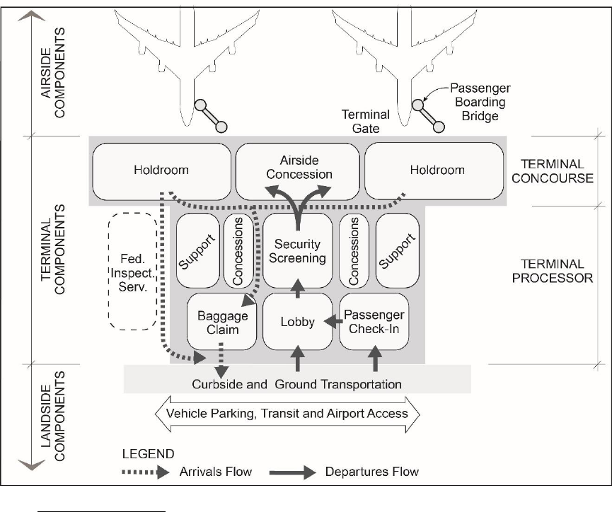
7/13/18 AC 150/5360-13A
6-2
Figure 6-1 Terminal Components
6.3.3 Airside Components.
6.3.3.1 Airside terminal facilities (see Figure 6-1) primarily include the area and facilities
required to accommodate aircraft parking, and aircraft support and servicing
operations:
Terminal gates or “contact“ parking positions – this portion of the apron is
used for parking aircraft to enplane and deplane passengers via passenger
boarding bridges (PBB), secure pedestrian walkways, or by walking to the
aircraft.
Remote aircraft parking positions – used for parking aircraft to enplane and
deplane passengers; passengers are transferred from the terminal to the
aircraft (or vice versa) via bus or other passenger transport vehicle. These
areas can also serve as remain overnight (RON) positions.
Aircraft deicing positions – deicing operations can be conducted at the
terminal gate, in a position pushed back from the gate, at a remote location
(i.e. a hardstand), or on an aircraft deicing apron. Dedicated areas
accommodate the aircraft for this process, and typically have space to stage
of deicing equipment for efficient and safe operations. They also have a

7/13/18 AC 150/5360-13A
6-3
system to recapture deicing fluid overspray on the ground (e.g. trench drains,
glycol recovery vehicles, etc.).
Aircraft service areas – areas on or adjacent to aircraft parking positions used
by service personnel for servicing aircraft. Also used for the staging of
baggage, freight, and other ground service equipment (GSE) for loading and
unloading aircraft.
Taxilanes – portion of the apron area that provides taxiing aircraft with access
between airfield elements (e.g., taxiway and runway) and aircraft parking
positions.
Aircraft maneuvering and pushback areas, and necessary wingtip clearances.
Service/security/emergency response areas – reserved areas or rights-of-way
for hydrant fueling systems, GSE, and emergency response vehicles, fire
suppression devices, maneuvering, staging and storage, security, and blast
fences.
Vehicle service roads – enable the safe movement of vehicles around the
airfield and minimizing interaction with aircraft.
Other equipment - aircraft waste dump/triturator station, electric vehicle
charging stations, etc.
6.3.3.2 The airside’s large spatial requirements, and fixed requirements for aircraft
wingtip separations and maneuvering clearances, typically drive the layout of the
terminal complex more than the passenger processing requirements within the
terminal building, or adjacent landside components. For most terminal planning
and design projects, it is important to formulate solutions based on the airside
component at the beginning of the process. This requires first identifying gate
requirements, and locating aircraft parking positions and their supporting
taxilanes to optimize the efficiency of the airfield. This is typically done before
planning the internal layout of the terminal building, and landside curb and
terminal roadway systems.
6.3.4 Terminal Components.
6.3.4.1 Terminal components (see Figure 6-1) include two main elements – the terminal
“processor” and the terminal concourse. The terminal processor typically
includes these components:
Public circulation and lobbies – public areas for passenger circulation,
services, and passenger/visitor waiting. These can also include areas for
general circulation, which include stairways, escalators, elevators, and
corridors.
Passenger check-in – areas used for ticket transactions, baggage check-in,
flight information, and space for airline administrative functions.
Security screening – a control point for inspection of passengers and baggage,
and controlling public access to sterile areas of the terminal. This area also
typically includes offices and support areas for administration, security staff,
7/13/18 AC 150/5360-13A
6-4
airport police and emergency responders. Checkpoints are typically situated
after the passenger check-in/ticketing lobby. However, some facilities have
“front-of-house” security screening checkpoints, where airport users must
clear security prior to entering the building.
Federal Inspection Services (FIS) – a control point for processing passengers
arriving on international flights.
Baggage processing – a nonpublic area for sorting, processing, and screening
baggage for departing flights, and baggage transfers from one flight to
another.
Inbound baggage facility – divided into a private area for receiving and sorting
baggage from arriving flights, and public areas for baggage claim by arriving
passengers and airline baggage service offices.
Other tenant space – areas reserved for ground operators, rental car
agencies, United Service Organizations (USO), etc.
6.3.4.2 The terminal concourse is essentially a passageway between the terminal
processor and the aircraft gates. Historically, most passengers have spent the
majority of their time in the concourse. In some cases, airports are able to
achieve layouts that provide sufficient comfort, gate proximity, and information
to give passengers confidence to spend more time away from the gate, where
they can utilize services and amenities (e.g., concessions). The following
elements typically comprise the terminal concourse:
Circulation corridors – public areas that facilitate the movement of
passengers from the terminal processor to the holdroom. The area and
movement of passengers can often be facilitated via moving walkways,
elevators, escalators, or people movers.
Holdroom(s) – an area for assembling and holding passengers before a flight
departure.
Passenger boarding bridge(s) – the structure(s) and/or facilities normally
located between the aircraft gate position and the concourse structure. This
enables the enplaning and deplaning of passengers.
6.3.4.3 The following elements can be located in both the terminal processor and the
concourse:
Airline operational areas – areas for airline personnel, equipment, and
servicing activities related to aircraft arrivals and departures.
Passenger amenities – areas normally provided in both the terminal processor
and concourse, particularly at larger airports. These amenities can include
restrooms, Service Animal Relief Areas, concessions, airline lounges,
children’s play areas, etc.
Building maintenance and utilities – areas reserved for terminal maintenance
and janitorial functions, mechanical, electrical, and plumbing systems,
information technology, storage, etc.

7/13/18 AC 150/5360-13A
6-5
Terminal services – public and private facilities that provide services
incidental to aircraft flight operations. These include food preparation and
storage, truck service docks, and miscellaneous storage.
Airport administration and services – areas dedicated to airport management,
operations, and maintenance functions.
6.3.5 Landside Components.
Landside terminal components primarily include the facilities and space required to enable
ground ingress and egress to and from the airport terminal (see Figure 6-1). These include:
Curbside – platforms and curb areas (including median strips) that provide passengers and
visitors with vehicle loading and unloading areas adjacent to the terminal processor. This
includes areas for private and commercial vehicles.
Pedestrian walkways – designated lanes and walkways for crossing airport roads. This
includes tunnels and bridges which provide access between curbs, automobile parking
areas, and the terminal.
Automobile parking – short and long-term parking for passengers, visitors, employees,
and rental car concessionaires. This can also include cell phone lots for vehicles awaiting
passenger arrivals, and staging areas for taxis, rideshare, and Transportation Network
Company (TNC) vehicles.
Access roadways – vehicular roadways providing access to the terminal curb, public and
employee parking, and regional roadway/highway system.
Rail and transit rights of way – access corridors that provide access to and from the
terminal facility, airport parking, and associated airport facilities.
Airport service roads – public and nonpublic roadways and fire lanes providing access to
other elements of the terminal complex and other airport facilities. Users and uses
include air freight, fuel facilities, taxi/TNC/limo, airport-related commercial development
(e.g., airport lodging or gas stations), and security/maintenance areas.
6.4 Terminal Siting Considerations.
6.4.1 For a new airport or major airport redevelopment, a new terminal site may be necessary or
desirable. A number of basic considerations affect terminal site selection:
Runway configuration. Runway configuration at an airport significantly impacts the
location of the apron-terminal complex. The terminal site should be located to minimize
aircraft taxiing distances and active runway crossings. In general, it is most practical to
locate the terminal centrally to the primary runway(s). At airports with more complex
runway configurations, siting may require detailed analyses to determine runway use,
predominant landing and takeoff directions, location and configuration of existing
taxiways, and the most efficient taxiway routings. Runway configuration may also restrict
ground access to certain areas of the airport and thus limit alternative terminal sites.
Airfield access. A critical consideration in the siting of terminal facilities is the layout of
terminal aprons, and access taxilanes or taxiways. While minimizing taxi distances is
desirable, safety considerations are of the utmost importance. Apply airfield design

7/13/18 AC 150/5360-13A
6-6
standards to reduce the probability of runway incursions. See Figure 6-2 for an example
of proper and improper taxiway design. The example is based on AC 150/5300-13, Airport
Design, which contains additional examples, rationale, and guidance on taxiway and
taxilane design.
FAA geometric design standards. FAA airport geometric design standards require specific
separation distances between terminal facilities and aircraft operational areas. These
standards include such minimum separation distances as those between a runway
centerline and aircraft parking aprons, buildings, and those between a taxiway centerline
and fixed/movable objects, etc. Refer to AC 150/5300-13, Airport Design, for information
on FAA airport geometric design standards.
Imaginary surfaces and airspace. Airport owner/operators must site passenger terminal
facilities and associated vehicles (e.g., aircraft at gate positions) in compliance with airport
imaginary surfaces and airspace. For detailed information see, AC 150/5300-13, Airport
Design, 14 CFR Part 77 - Safe, Efficient Use, and Preservation Of The Navigable Airspace,
and United States Standard for Terminal Instrument Procedures (TERPS).
When administering Title 14 of the Code of Federal Regulations 14 CFR Part 77, the FAA’s
prime objectives are to promote air safety and efficient use of navigable airspace. To
accomplish this, the FAA conducts aeronautical studies based on information provided by
project proponents on FAA Form 7460-1, Notice of Proposed Construction or Alteration.
Proponents must file this form for any construction or alteration that may affect navigable
airspace. Additional information is available on the Obstruction Evaluation / Airport
Airspace Analysis (OE/AAA) website.
Airport traffic control tower (ATCT) and ramp control tower line-of-sight. It is critical to
ensure the terminal building, related structures, and aircraft parked at gates will not
compromise visibility from the ATCT. An unobstructed view of all controlled movement
areas is required. This includes all runways, taxiways, any other landing areas, and air
traffic in the vicinity of the airport. See AC 150/5300-13, Airport Design, and FAA Order
6480.4, Airport Traffic Control Tower Siting Process, for additional information.
Local building code. Airport owners/operators should coordinate with local government
to ensure compliance with local building code, especially during the design phase of a
project.
Terrain. It is important to consider airport topography and the site’s relation to flood-
prone areas when selecting a terminal building site.
Sustainability. Sustainable terminal siting focuses on minimizing taxi distances from
runways and taxiways to reduce fuel consumption and emissions of taxiing aircraft,
minimizing noise impacts to surrounding communities, and convenient, proximate access
to intermodal transportation options. Chapter 9 includes additional information on
sustainability considerations for terminal siting.
Environmental factors. The siting or expansion of a passenger terminal must also consider
potential environmental impacts, which could influence the location or feasibility of a site.
National Environmental Policy Act (NEPA) analyses are required for projects that require a
federal decision or involve federal funding. For comprehensive information on NEPA
requirements see FAA Order 5050.4, National Environmental Policy Act (NEPA)
Implementing Instructions for Airport Actions.
7/13/18 AC 150/5360-13A
6-7
Access to other transportation modes. As noted above, a sustainable passenger terminal
should provide the most direct/shortest routing to the access transportation system(s)
(e.g. roadway system, public transit, local trails for bicycle/pedestrian access, etc.).
Expansion potential. Whether the initiative is an expansion project or the development of
a new terminal, airports should develop a flexible terminal layout that provides
reasonable allowances for growth and operational changes beyond forecasted needs.
6.4.2 Existing and planned facilities. Existing and planned structures and utilities should be carefully
inventoried when planning new or expanded terminal facilities. In all cases, planners should
analyze existing or planned locations of an FAA control tower, navigational aids, weather
equipment, etc., to ensure terminal development will not interfere with line-of-sight or other
operational restrictions associated with these facilities.

7/13/18 AC 150/5360-13A
6-8
Figure 6-2 Examples of Not Recommended and Recommended Taxiway Design (per AC 150/5300-13)

7/13/18 AC 150/5360-13A
6-9
6.5 Terminal Configurations.
Four basic terminal configurations are illustrated in Figure 6-3 and described in the following
sections. These configurations primarily differ in the way passengers move from the terminal
processor to the aircraft gates. Specific dynamics of each include overall size, physical space
and land configuration, as well as cost to operate. Although the following discussion focuses
on the four basic configurations, many existing and planned airport passenger terminals use a
“hybrid concept” with a combination of these configurations. The planning team would
typically begin exploring the various configurations once the sizes of functional components
are determined and they evaluate the building site to see how these components can be
accommodated. Operational efficiency of the terminal complex is an overarching concept at
this stage of the process.
Figure 6-3 Example Terminal Configurations
6.5.1 Linear Terminal Configuration.
6.5.1.1 Linear terminals are long buildings with aircraft parked perpendicularly along the
airside face of the main terminal processor. There can be expansion potential to
either side. The length is primarily driven by the number of gates and their sizing
requirements, but limited by walking distances and the capacity to build features
that extend those distances (air trains, moving walkways, etc.). Typically, a
concourse may be located parallel to or within the terminal face nearest the
apron, with access to the terminal and aircraft gate positions at regular intervals.
6.5.1.2 With the advent of security checkpoints, the linear concept lost one of its main
advantages – easy access and relatively short curb-to-gate walking distances for
originating and/or terminating passengers. It is, however, still ideal for smaller
terminals that largely serve O&D activity.

7/13/18 AC 150/5360-13A
6-10
6.5.1.3 Airports with linear terminal configurations include San Jose and Dallas Fort
Worth International (see Figure 6-4).
Figure 6-4 Example Linear Terminal Configurations
San Jose International Airport Dallas Fort Worth International Airport
6.5.2 Pier Configuration.
6.5.2.1 In the pier configuration, aircraft are parked along piers or concourses extending
from the terminal processor. Access to the terminal processor is at the base of
the concourse or pier. Piers can have various shapes. Aircraft can use both sides
of the piers. Aircraft are usually arranged around the axis of the pier in a
perpendicular, nose-in position. Each pier typically has rows of aircraft gate
positions on one or both sides, with circulation space running along the axis of
the pier for enplaning and deplaning passengers.
6.5.2.2 Double-loaded pier concourses efficiently utilize space and can be an effective
solution in land-constrained situations. However, they may also cause longer
passenger walking distances, conflicting passenger movements between arriving
and departing passengers, and limited curbside space.
6.5.2.3 Airports with pier configurations include La Guardia International, Washington
Reagan National, Miami International, George Bush-Houston Intercontinental,
and Phoenix-Sky Harbor International (see Figure 6-5).

7/13/18 AC 150/5360-13A
6-11
Figure 6-5 Example Pier Terminal Configurations
Miami International Airport George Bush Intercontinental Airport
6.5.3 Satellite Configuration.
6.5.3.1 The satellite configuration consists of a concourse or concourses, and aircraft
gates that are physically apart from the main terminal processor. Since aircraft
enplaning and deplaning is accomplished remotely, satellite configurations
require a connection between the concourse and terminal processor for
passengers, baggage, and other materials. These facilities can be connected at
grade, above grade, or below grade. Tunnels or bridges can accommodate
walkways, moving walkways, or Automated People Movers (APM). Underground
facilities for mechanical conveyance of passengers, baggage, and other materials
can add significant costs to the concept. However, movement of passengers,
baggage, and other goods on the surface or above grade can complicate and
hinder the movement of aircraft and other vehicles on the airside.
6.5.3.2 The satellite configuration results in efficient space utilization. It is typically
suitable for airports that have a high percentage of connecting traffic. A satellite
configuration may also be appropriate for airports where the size and
configuration of available real estate limits other options.
6.5.3.3 Connecting passengers do not normally require landside facilities. Therefore,
passenger processing and curbside facility needs are lower than for facilities with
higher O&D numbers. However, satellite concepts are ill-suited for connecting
passengers who may have to move among multiple satellites. Curbside
congestion can also be a problem if the ratio of O&D and connecting passengers is
not properly balanced.
6.5.3.4 Satellite concourses are typically associated with higher operating and
maintenance costs because redundant functions and facilities are required in the
terminal processor and auxiliary satellites (e.g., key passenger services and
support functions), and the physical distance between the processor and
concourses. Satellite configurations also tend to have less intuitive wayfinding.

7/13/18 AC 150/5360-13A
6-12
6.5.3.5 Airports with satellite terminal configurations include Hartsfield-Jackson Atlanta
International, Denver International, and Chicago O'Hare International (see Figure
6-6).
Figure 6-6 Example Satellite Terminal Configurations
Atlanta International Airport Denver International Airport
6.5.4 Remote Configuration.
6.5.4.1 In the remote configuration, aircraft and aircraft-servicing functions are placed in
a remote location. Aircraft are not “connected” to a physical terminal or
concourse. Rather, transport between the aircraft and the terminal is provided
by vehicles for enplaning and deplaning passengers, baggage, and other goods
and personnel. This configuration is common in European and South American
airports. It is uncommon in the United States.
6.5.4.2 The original remote configuration concept envisioned the transporter or
conveyance being the holdroom or departure lounge (a “mobile lounge”). The
common application today is a busing operation. This requires passengers to wait
in a traditional holdroom and board a bus before being driven out to the aircraft.
Due to the extra processing steps and realities of moving a potentially large
number of passengers, the remote configuration provides a lower level of
passenger service (and in some cases, passenger convenience) than contact gates.
6.5.5 Centralized and Decentralized Terminals.
6.5.5.1 The main terminal processor for each configuration may either be centralized or
decentralized (depending on how the concourse connector is extended, or linked,
to the terminal processor[s]). In a centralized configuration, there is a single
terminal processor that accommodates all passengers, baggage, security, and
other “processing”-related activities. In a decentralized configuration, multiple
terminal processors serve different concourses, piers, or satellite concourses.
6.5.5.2 Often, a dominant air carrier at an airport will negotiate a multiple processor
configuration. This allows for independent control of their facilities and
operations. A significant international operation at an airport may also be a
driver for a separate terminal because of the unique requirements and facility
7/13/18 AC 150/5360-13A
6-13
demands of international travel. However, changes in pre-clearance alternatives
are beginning to blur the line between domestic and international operations at
some airports. Current trends should be considered when planning for
international operations. Multiple terminal facilities may present long-term
challenges for the airport. They are inherently less efficient due to spatial and
functional redundancy, and reduced flexibility for airlines to grow, downsize, or
relocate within the terminal complex.
7/13/18 AC 150/5360-13A
6-14
PAGE INTENTIONALLY LEFT BLANK

7/13/18 AC 150/5360-13A
7-1
CHAPTER 7. TERMINAL APRON AREAS
7.1 General.
7.1.1 This chapter describes key terminal apron elements and provides general guidelines for
planning terminal apron areas.
7.1.2 Planning terminal apron areas occurs at various stages in the terminal planning process (e.g.;
for a new facility when the terminal building layouts and geometry are being drawn at a
conceptual level, for an existing facility where the fleet mix has changed or when planning a
terminal expansion, etc.).
7.1.3 The terminal apron area is the portion of pavement between the face of the terminal building
and the movement area. The primary functions of the apron area are to: (a) provide a safe
and efficient space for aircraft to maneuver to from the airfield to the terminal building, (b)
accommodate aircraft parking for enplaning and deplaning passengers, and (c) accommodate
maneuvering and staging of GSE and support vehicles for aircraft servicing. Key elements of
the apron area are:
Apron pavement – surface area designed to provide a firm, stable, smooth, all-year, all-
weather surface adequate to support the design aircraft. See AC 150/5320-6, Airport
Pavement Design and Evaluation, for guidance on airport pavement design.
Aircraft parking gate – pavement area for aircraft parking. Examples include contact gates
with passenger boarding bridges, ground loaded gates, remote gates, and RON positions.
Passenger boarding bridge (PBB) – enclosed structure that allows for the controlled
movement of passengers between the concourse and the aircraft. These bridges often
contain remote power and cooling systems for aircraft parked at the gate.
GSE maneuvering and staging areas – apron area adjacent to the aircraft parking position.
Used for maneuvering and parking aircraft servicing vehicles such as baggage tugs, fueling
trucks, catering trucks, and maintenance equipment.
Vehicle service roads – marked pavement areas that provide GSE and service vehicle
access to move about the apron or circulate around aircraft. These are typically two-way
roads that are 20 to 25 feet wide.
Taxilanes – A taxiway designed for low-speed and precise taxiing. Taxilanes are usually,
but not always, located outside the movement area. They provide access from taxiways
to aircraft parking positions, other terminal areas, and other connector taxiways.
Utilities –infrastructure for servicing aircraft parked at aircraft parking gates. Examples
include hydrant fueling, apron lighting, grounding systems, power, conditioned air,
stormwater, deicing, and fire deluge systems.

7/13/18 AC 150/5360-13A
7-2
7.1.4 Figure 7-1 is a generalized depiction of the terminal apron area. The optimum apron design
for a specific airport will depend upon available space, aircraft fleet mix, and terminal building
configuration.
Figure 7-1 TERMINAL APRON AREA
7.2 Aircraft Parking Gates.
There are four types of aircraft parking gates: contact, ground-loaded, and remote gates, and
RON positions. An airport owner/operator’s or airline’s choice among gate types depends on
passenger level-of-service objectives, aircraft fleet and operations, and the characteristics of
the concourse geometry or other physical constraints. The following provides a description of
each gate type.
7.2.1 Contact Gates.
A contact gate is an aircraft parking position that is connected directly to the concourse via a
PBB. Contact gates are the most common type of gate in the United States. They provide the
highest level of passenger service because of the short distance between the holdroom and
aircraft, and the controlled environment of the PBB. In certain constrained concourse
geometries or uniquely shaped terminal apron areas, a loading bridge is attached to a fixed
bridge extension.

7/13/18 AC 150/5360-13A
7-3
7.2.2 Ground-Loaded and Remote Gates.
7.2.2.1 Ground-loaded gates are located adjacent to the concourse, but passengers move
between the concourse and aircraft via the apron pavement instead of a PBB. In
typical ground-loaded operations, passengers wait to board the aircraft from a
holdroom, and access the aircraft through a covered walkway and stairs. In the
United States, ground loading typically occurs for smaller aircraft and aircraft with
low door heights (such as regional jets or turbo-prop aircraft, which are
incompatible with traditional PBBs). Ground loading provides a lower level of
service than contact gates because passengers must walk longer distances, climb
stairs (normally with carry-on luggage), and are exposed to weather.
7.2.2.2 Remote gates are similar to ground loaded gates, but remote gates are located
apart from the concourse. Buses are required to transition passengers between
the concourse and the aircraft. Remote gates are a low cost alternative to
constructing additional concourse infrastructure. They are often used in
situations where passenger demand exceeds terminal capacity.
7.2.3 Remain Overnight (RON) Positions.
RON positions are used for parking non-active aircraft away from the terminal. They provide
additional positions and make gates available for passenger operations. In the U.S, RON
positions are commonly used for overnight aircraft parking. RON positions are essential at
international airports where aircraft typically remain on the ground for longer periods of time,
or at airports with heavy, frequent service peaks.
7.3 Aircraft Parking Gate Requirements.
7.3.1 The number and size of aircraft parking gates dictate terminal building geometry, and linear
building frontage requirements. There are many methods to calculate gate requirements
depending on the level of detail required. At the master plan level, either annual gate
utilization or peak hour utilization in combination with aircraft type is used to determine gate
requirements. At a more detailed design level, peak hour utilization is more appropriate.
7.3.2 Annual gate utilization is calculated by dividing the total number of annual average day
aircraft departures by the total number of aircraft parking gates (number of turns per day at a
gate). Future gate requirements are determined by applying this ratio (and/or adjusting it up
or down) to forecast annual average day aircraft operations.
7.3.3 As described in Chapter 4, Planning Methodologies and Tools, peak hour utilization and
resulting gate requirements can be determined through the development of a future “design
day” flight schedule based on forecast activity. A design day flight schedule provides a
distribution of flights and passengers on an hourly basis throughout the design day. The peak
hour is identified as the hour in the schedule that includes the highest volumes of activity.
Future peak hour volumes are determined by applying appropriate growth rates to the
existing design day flight schedule and increasing activity levels to meet forecast demand.
This is accomplished via a combination of “up-gauging” aircraft types (utilizing larger aircraft
with higher numbers of seats per plane) and introducing additional flights. This combination

7/13/18 AC 150/5360-13A
7-4
depends on the most likely strategies employed by airlines at the airport. Other operational
factors such as common use versus preferential use gates should be considered when
determining peak hour gate requirements.
7.3.4 Detailed explanations of methodologies used to determine gate requirements can be found
in:
ACRP Report 23, Airport Passenger-Related Processing Rates
ACRP Report 25, Airport Passenger Terminal Planning and Design
7.3.5 Aircraft Parking Gate Layouts.
7.3.5.1 The layout of aircraft parking positions is an extremely important element that
requires careful consideration during related terminal planning and design
efforts. Aircraft parking position layouts can vary significantly depending on
airport or airline practices, and tenant and airline lease negotiations. These
variations can impact other aspects of the terminal facility. Basic criteria
associated with parking position layouts are described below and illustrated in
Figure 7-2.
Gate width – the width of the aircraft parking position envelope. It is one of
the most critical factors that influences the length of the terminal or
concourse. There are three main approaches to determining the width of a
gate or gates: by Airplane Design Group (ADG), by the most critical aircraft,
or by group of critical aircraft. To ensure proper planning, the choice of
aircraft, equipment specifics, and accurate aircraft dimensions must be
determined with care. The aircraft type(s) and configuration (e.g. with or
without winglets) used to size a gate should be carefully coordinated and
validated with all stakeholders using dimensions from the aircraft
manufacturers to ensure adequate space is allocated.
Wingtip Clearance – the distance between an aircraft wingtip to adjacent
parked aircraft wingtip or building façade. Adequate clearance between and
around aircraft wingtips is necessary to allow safe and efficient movement of
aircraft to and from aircraft parking positions, to prevent the collision of
maneuvering aircraft, to allow adequate GSE access and maneuverability, and
to allow unobstructed access for emergency response vehicles (e.g., Aircraft
Rescue and Fire Fighting, emergency medical responders, and airport police).
The industry-accepted distance for wingtip clearance dimensions when
planning or designing aircraft parking positions for commercial service aircraft
are 25-feet from one aircraft to another parked aircraft, and 45-feet for
inboard pier gates from the wingtip to the adjacent building façade. See
Figure 7-2 for a graphical depiction. It should be noted that the actual
dimensions used by airlines can vary depending on their policies and
operational preferences
Nose to building clearance – distance from the nose of the aircraft to the
concourse for pushback tug maneuvering and other safety requirements. The
distance can also be driven by the required length of the PBB to meet ADA
slope requirements for the design aircraft.

7/13/18 AC 150/5360-13A
7-5
Gate depth – distance from the face of the concourse to the edge of the
vehicle service roads or taxiway/taxilane object free area for parking aircraft.
The depth of the gate is determined primarily by the length of the largest
aircraft projected to be accommodated at the position, and the nose to
building clearance.
GSE parking, storage, and recharging area– marked locations on the apron
where GSE such as fueling trucks, baggage tugs, and other equipment
servicing the aircraft are stored. For airports with electric GSE (EGSE), marked
locations for EGSE charging stations should also be included.
Vehicle service roadways – designated roadways for service vehicles to
maneuver safely on and around the apron area. These can be located behind
the aircraft’s tail (back of stand), in front of the aircraft nose (head of stand),
between wingtips, or routed beneath the concourse. The limits of vehicle
service roadways should be clearly marked to ensure lateral and vertical
clearance are maintained between parked aircraft and vehicles traversing the
service roads.
Airport traffic control tower and ramp control tower line of sight – line of
sight refers to visibility from the ATCT cab. There should be an unobstructed
view of all controlled movement areas of an airport, including all runways,
taxiways, and any other landing areas, and air traffic in the vicinity of the
airport. During the terminal planning process, it is critical to ensure that
facility development does not impact visibility from the ATCT cab. See AC
150/5300-13, Airport Design, and FAA Order 6480.4, Airport Traffic Control
Tower Siting Process, for additional information.
Airport imaginary surfaces and airport design surfaces - These surfaces must
be carefully considered during facility development to ensure compatibility
with existing and planned airport configurations. See AC 150/5300-13,
Airport Design, 14 CFR Part 77, and FAA Order 8260.3, United States Standard
for Terminal Instrument Procedures (TERPS), for information on airport
imaginary surfaces and airport design surfaces.
Jet blast – This refers to the high-velocity exhaust from jet engines. This is a
critical design factor on aircraft parking aprons in order to protect passengers,
operations staff, adjacent aircraft, airport facilities, etc. For guidance on the
effects and treatment of jet blast, and criteria for design and layout, see AC
150/5300-13, Airport Design.
Utilities – The location of utilities (e.g., electrical, plumbing, fueling, and
communications) is a critical consideration when laying out or reconfiguring
aircraft parking.
7.3.5.2 Detailed information regarding the layout of aircraft parking positions, apron
design, and related considerations can be found in:
FAA AC 150/5300-13, Airport Design
FAA Order 6480.4, Airport Traffic Control Tower Siting Process

7/13/18 AC 150/5360-13A
7-6
14 CFR Part 77 - Safe, Efficient Use, and Preservation Of The Navigable
Airspace
ACRP Report 25, Airport Passenger Terminal Planning and Design, Volume 1
ACRP Report 96, Apron Planning and Design Guidebook
FAA Order 8260.3, United States Standard for Terminal Instrument Procedures
(TERPS)
FAA AC 150/5340-1, Standards for Airport Markings
Airports Council International (ACI), Apron Markings and Signs Handbook
FAA AC 150/5320-6, Airport Pavement Design and Evaluation
7.3.6 Aircraft Parking Gate Operations.
The most common type of aircraft parking operation at U. S. airports taxi-in/push-back: when
aircraft taxi into the gate parking position using the aircraft engines, while a ground tug is
used to push the aircraft back from the gate. Power-out operations - when an aircraft leaves
the gate position using its own power - are much less common. Advanced docking systems -
automated systems that can precisely guide aircraft to the aircraft parking position stop bars
and dock the PBB to the aircraft – are also commonly utilized.
Figure 7-2 Aircraft Parking Gate Layout
7.3.7 Boarding Bridges and Fixed Utilities.
7.3.7.1 The two most common PBBs are “fixed” and “apron drive.” Fixed PBBs are
connected directly to the concourse or to a fixed bridge extension. They have
limited flexibility (they are not able to rotate on a pedestal), and can only expand

7/13/18 AC 150/5360-13A
7-7
and contract from a single point. Apron drive PBBs can expand and contract like a
fixed PBB, but also rotate or move about from a static pedestal. Apron drive PBB
flexibility is desirable because aircraft types and other procedures change
frequently.
7.3.7.2 Aircraft fleet mix is a key factor in determining the number, location, and position
of PBBs. Passenger flow volumes associated with a single aisle, narrow-body
aircraft (e.g., ADG-III or B757) can typically be accommodated by a single PBB.
Twin aisle, wide-body aircraft (e.g., ADG-IV and larger) may require more than
one PBB in some cases because they have greater passenger flow volumes (due to
the number of seats and egress doors).
7.3.7.3 PBBs should be positioned to maintain maximum flexibility to accommodate as
many aircraft types as possible (in alignment with the mix of aircraft). Also, to
meet ADA requirements, PBBs should also be sited and specified so that the slope
of the bridge(s) is (are) no greater than 12:1 for the gate’s mix of aircraft.
7.3.7.4 PBBs and adjacent terminal apron areas contain many utilities that service an
aircraft at a gate. This includes ground power, conditioned air, potable water,
and aircraft fueling. There are a number of industry-recognized publications that
explain these utilities and associated planning considerations. Comprehensive
passenger boarding bridge and utility standards and requirements can be found in
the following industry recognized publications:
FAA AC 150/5220-21, Aircraft Boarding Equipment
FAA AC 150/5300-13, Airport Design
ACRP Report 25, Airport Passenger Terminal Planning and Design
ACRP Report 96, Apron Planning and Design Guidebook
7.3.7.5 National fire code regulations related to the apron area can be found in National
Fire Protection Association (NFPA) Standard 415, Standard on Airport Terminal
Buildings, Fueling Ramp Drainage, and Loading Walkways, (note: please review
other related NFPA codes and standards which may also be applicable). ADA
compliance requirements can be found in the U.S Department of Justice Civil
Rights Division, ADA Standards for Accessible Design. AC 150/5360-14, Access to
Airports by Individuals with Disabilities, provides additional information to assist
airports in complying with applicable laws and regulations for individuals with
disabilities.
7.4 Taxilanes and Aprons.
7.4.1 Taxilanes are paved areas designed for low speed and precise taxiing. Taxilanes are usually,
but not always, located outside the movement area, providing access from taxiways (usually
an apron taxiway) to aircraft parking positions and other terminal areas. Both single and
multiple taxilanes should be considered for aircraft to maneuver around a concourse, parked
aircraft, vehicles, etc. For drainage requirements, fire protection, and ease of aircraft
movements, apron gradients should meet recommended design criteria in AC 150/5300-13,

7/13/18 AC 150/5360-13A
7-8
Airport Design, and always slope away from the concourse and fixed passenger boarding
bridges.
7.4.2 An explanation of the principles and design standards for taxilanes and aprons can be found
in:
FAA AC 150/5300-13, Airport Design
ACRP Report 96, Apron Planning and Design Guidebook
7.5 Apron Lighting.
7.5.1 Most outdoor areas associated with the terminal apron require some degree of illumination
during nighttime and low-visibility conditions. Lighting levels in the vicinity of aircraft parking
areas and the terminal apron should be of sufficient intensity to provide a safe, secure, and
efficient operating environment for airport operations during nighttime conditions and
inclement weather (e.g. to permit deicing at the gate).
7.5.2 Mounted floodlights are the preferred method of lighting the apron area. Floodlights should
be sited, aimed, and shielded to avoid glint and glare to pilots and air traffic controllers
without reducing the level of illumination in critical areas. To enhance visibility, install
uniform illumination across lighted areas using multiple overlapping light sources from
different directions to minimize strong ground shadowing. Airports should coordinate with
applicable airport stakeholders (e.g., airport staff, airline management and ground service
providers), ATCT staff, and local FAA Office of Airports personnel when designing or modifying
apron lighting systems. Airport airspace should also be considered when installing lighting
systems (See 14 CFR Part 77 and FAA Order 8260.3 for additional information on airport
airspace).
7.5.3 Additional information on apron lighting can be found in:
AC 150/5300-14C, Design of Aircraft Deicing Facilities. The document includes a section
specifically on lighting requirements for aircraft deicing facilities.
ACRP Report 25, Airport Passenger Terminal Planning and Design
Illuminating Engineering Society (IES), Outdoor Lighting for Airport Environments (RP-37-
15)
14 CFR Part 77 - Safe, Efficient Use, and Preservation Of The Navigable Airspace
7/13/18 AC 150/5360-13A
8-1
CHAPTER 8. AIRPORT GROUND ACCESS AND CIRCULATION
8.1 General.
This chapter provides guidance on planning airport ground access, circulation, and automobile
parking facilities. It also includes a discussion of planning studies, key roadway and parking
components (including key variables and inputs needed to plan for them), public transit and
automated people movers, signage and wayfinding, and emergency response vehicle routes.
8.2 Planning Studies.
The planning of new airport roadways and parking facilities should occur at the same time as
planning the terminal building, air cargo areas, general aviation terminals, and other land uses
the roadways and parking facilities are intended to serve. Subsequent planning studies are
frequently conducted to: (a) develop options to increase capacity, (b) address operational
concerns, or (c) accommodate changes in the use of the terminal building or other land uses.
It is important that the terminal roadways and parking facilities are integrated into the overall
terminal planning process to ensure a balanced system.
8.3 Key Roadway and Parking Components.
The components of an airport roadway and parking network are described below, and
depicted in Figure 8-1.
Access roadways – provide for the flow of traffic between the regional roadway network,
local roadways, and the terminal area and other major traffic generators located on the
airport. These include air cargo/freight terminals, general aviation terminals, and airline
maintenance centers. Access for alternate modes, such as bicycle and pedestrian access,
may also be part of the transportation network.
Curbside roadways – located adjacent to the terminal ticket lobby and baggage claim
areas, these are used to drop off and pick up airline passengers and their baggage.
Recirculation roads – are for motorists and commercial vehicles going back to the terminal
or to a parking entrance after dropping off a passenger, or going to pick up a passenger
after exiting a parking facility.
Public parking structures or lots – these include: (a) short-term parking serving visitors
(such as meeters/greeters and well-wishers) parking their vehicles for a short period; (b)
long-term parking serving airline passengers parking for a day or more; and (c) other
parking offerings such as remote/economy parking, cell phone lots, Transportation
Network Company (TNC)/Rideshare/Peer to Peer staging lots/assignment areas , valet
parking or corporate reserved parking, and bicycle parking (typically for airport
employees).
Employee parking – reserved for persons working for the airport, airline employees
(including based and non-based flight crews), and other tenants.
Employee Screening – areas for screening employees that work in secure areas. Screening
can be accomplished outside the terminal building (e.g., at the curbfront) or inside the

7/13/18 AC 150/5360-13A
8-2
building; either in an area dedicated to this function or adjacent to passenger security
screening areas.
Service roads – provide access to and circulation between non-terminal area land uses.
They are primarily used by air cargo, service/delivery, and airport operations/employee
vehicles.
Figure 8-1 Airport Roadway and Parking Components
Source: ACRP Report 40, Airport Curbside and Terminal Area Roadway Operations

7/13/18 AC 150/5360-13A
8-3
Airfield roads – located within the aircraft operating area and used only by authorized
vehicles and drivers.
Rental car areas – used to facilitate rental and return of cars, car storage, and
ready/return functions (fueling, washing, and light maintenance) for rental vehicles.
Commercial vehicle hold areas – used for brief parking or holding/staging of taxicabs,
limousines, charter bus/vans, and other vehicles waiting for the arrival of airline
passengers.
Rideshare vehicle hold areas – specifically designated areas for staging and picking up
passengers (airports are handling these services in a variety of ways).
Loading docks – located in the terminal building where goods and products for food,
beverage, and retail concessionaires are delivered and trash is removed.
8.4 Roadways.
8.4.1 Planning and operation of airport roadways differs dramatically from planning and operation
of regional roadways. This is because motorists using regional roadways drive on the same
roadways many times each week and are thoroughly familiar with the exit/entry locations,
roadway directional signs, and likely points of congestion. In contrast, most motorists using
airport roadways drive to the airport infrequently, and are unfamiliar with the exit/entry
locations, roadway signage, and likely points of congestion. In addition, due to concerns
about potential delays, unfamiliarity with check-in procedures, or the desire to greet an
arriving passenger on time, those traveling to an airport face more stress than typical
commuters. This unfamiliarity and stress may be exacerbated by the relative complexity of
airport roadways (as compared to regional roadways and arterials). Airport roadways often
contain more closely spaced decision points, more complex signs, and a higher proportion of
taxicabs, limousines, scheduled and chartered buses/vans, shared-ride vans, courtesy vehicles
serving hotel/motels, and rental cars, (collectively referred to as commercial vehicles), and
more parking lots.
8.4.2 Planning for airport roadways and parking facilities begins with establishing existing and
future levels of demand, which is prepared as part of the inventory and forecast steps in the
airport planning process. Airline passengers and visitors using the terminal buildings and other
facilities drive this demand. The estimated demand is compared with the calculated capacity
of the existing or proposed roadway and parking facilities to establish the ratio between
demand and capacity. The demand/capacity ratio helps define the LOS* for each roadway
segment or parking facility.
* Level of Service (LOS) is a qualitative measure used to describe the quality of traffic flow experienced by a
motorist (or other facility user). Six levels of service are defined, with LOS A being the best operation (i.e., free
flow conditions with no delays or congestion) and LOS F representing instances where demand exceeds capacity,
resulting in frequent delays and prolonged congestion. LOS C, which represents stable flows at or near free-flow
conditions with drivers experiencing comfortable and safe operations, is frequently selected as a goal for the
planning of airport roadways due to the consequences of passenger delays and customer experience desired by
most airports. The Transportation Research Board’s Highway Capacity Manual presents a detailed description of

7/13/18 AC 150/5360-13A
8-4
8.4.3 Roadway Level of Service.
Roadway LOS goals should be established at the outset of a planning effort. As the planning
process continues, the calculated LOS for each roadway segment and parking facility should
be compared with these goals. The plans for facilities not providing satisfactory LOS should be
modified to increase capacity and improve LOS (e.g., by adding roadway lanes, parking spaces,
parking exit lanes, or eliminating unsatisfactory weaving operations).
8.4.4 Roadway Requirements.
8.4.4.1 Airport access and circulation roadways are designed to accommodate the peak
hour traffic demands projected for each roadway link or component. The peak
hour volumes may be defined as the volumes occurring during the peak hour of
an average day during the peak month, the 30
th
highest hour, or the peak hour
occurring during a standard busy day. The peak hour for vehicles transporting
originating airline passengers to the airport typically precedes the peak aircraft
departure hour by 1 to 2 hours, while the peak hour for vehicles transporting
terminating airline passengers from the airport typically lags the peak aircraft
arrival hour by the same amount. The amount of “lead” and “lag” time depends
upon the proportion of international/domestic passengers, business/leisure
passengers, aircraft size and load factors, airport size, security requirements, and
other factors.
8.4.4.2 Two common methods to determine roadway requirements or peak hour
roadway traffic volumes are summarized below:
1. Volume and Mode Choice. Calculate the volumes generated by each airport
land use (e.g., airline passenger terminal building, air cargo areas, and
general aviation terminal) and determine the access/egress routing patterns
of these traffic volumes. Future roadway traffic volumes can be calculated
based upon estimates of the number of originating and terminating airline
passengers, number of employees, and volume of cargo, while adjusting for
future travel patterns (e.g., changes in the proportion of traffic
approaching/departing the airport from different directions), mode choice
(e.g., anticipated increase in the use of public transit), and other changes.
However, this method requires a large amount of input data to calculate the
volume of traffic generated by airline passengers, visitors and employees,
and airport service and delivery vehicles, and to determine the current
circulation patterns of these vehicles.
2. Peak Hour. Increase the existing peak hour traffic volumes on each roadway
link in direct proportion to the forecast growth of design hour airline
passengers or other indices of future growth. Existing peak hour traffic
the Level of Service (LOS) concept and the methods used to calculate LOS on roadways having uninterrupted traffic
flows (e.g., limited access freeways and arterials) and interrupted flows (e.g., signalized and stop sign controlled
roads and streets).

7/13/18 AC 150/5360-13A
8-5
volumes can be determined through automated traffic surveys or manual
surveys if vehicle classification data are needed.
8.4.4.3 ACRP Report 40, Airport Curbside and Terminal Area Roadway Operations,
presents detailed information about calculating airport roadway requirements.
8.5 Terminal Curbside.
Curbside roadways consist of inner lane(s) where vehicles typically stop in a nose-to-tail
manner to drop off or pick up passengers, an adjacent maneuvering lane, and one or more
bypass lanes. Usable curbside space does not include space occupied by crosswalks, reserved
for police, emergency, or other vehicles, or otherwise not available to private or commercial
vehicles. However, airport owners/operators should consider the extent of double parking at
the inner lanes, the number of bypass lanes, and the interaction between bypass traffic and
traffic entering and exiting the curbside lanes. For example, three-lane curbside roadways are
undesirable because when double-parking occurs, only a single by-pass lane remains. Traffic
flow on the remaining single lane may be obstructed or delayed as double-parked vehicles
enter and exit the bypass lane. A generalized depiction of the terminal curbside is presented
on Figure 8-2.

7/13/18 AC 150/5360-13A
8-6
Figure 8-2 Airport Curbside Components
8.5.1 Curbside Level of Service.
The LOS of a curbside roadway is determined by analyzing the demand/capacity or
volume/capacity ratio for both the inner curbside lanes and maneuver lanes, with the lanes
having the poorest level of service governing the roadway’s LOS level. The LOS on the inner
curbside lanes is defined by the proportion of double-parked vehicles with a curbside having
30% of the vehicles double-parked (assuming the entire inner lane is occupied) defined as LOS
C. The volume/capacity of the bypass lanes is determined by comparing the volume of bypass

7/13/18 AC 150/5360-13A
8-7
traffic with the capacity of the bypass lanes, which varies depending on the LOS of the
curbside lanes.
8.5.2 Curbside Requirements.
8.5.2.1 Airport curbside roadway requirements are typically calculated to accommodate
the volume of traffic occurring during the peak 15 to 20 minutes of the peak hour.
This is because traffic flows are not distributed uniformly throughout the peak
hour, and a sudden peak or burst of traffic can result in congestion and delays. In
addition, curbside demand is not distributed uniformly along the face of the
terminal. It tends to be higher near skycap bag check-in locations, doorways
serving popular airlines, and in locations away from columns and the most distant
curbside sections.
8.5.2.2 The following inputs are used to calculate airport curbside roadway requirements.
Volume –the number of vehicles stopping at each curbside to drop off or pick
up airline passengers, and number of “bypass” vehicles driving past but not
stopping at a curbside.
Vehicle mix – the different types of private and commercial vehicles.
Vehicle dwell times – the length of time vehicles remain stopped at the
curbside.
Curb space – the average length of curb space occupied by each type of
vehicle, including the space required to maneuver into and out of the
curbside area.
8.5.2.3 The level of curbside traffic enforcement an airport owner/operator uses can also
be a significant factor in determining curbside roadway requirements.
8.5.2.4 For detailed information about airport roadway capacities, commercial ground
transportation and LOS, see:
ACRP Report 40, Airport Curbside and Terminal Area Roadway Operations
Intermodal Ground Access to Airports, a Planning Guide (FAA, FHA, Bellomo-
McGee, Inc., 1996)
ACRP Report 146, Commercial Ground Transportation at Airports: Best
Practices
8.6 Parking Facilities.
Parking facilities accommodate airline passengers, airport visitors, and people working at the
airport. Planning and operating airport parking facilities is different from parking facilities for
offices, retail centers, hospitals, or downtown areas. Airport parking facilities can be very
large. Some contain over 5,000 spaces. And unlike parking facilities serving other uses, a high
percentage of the spaces are occupied for 24 hours or more. Airport parking facilities are also
an important source of airport generated revenue and an important contributor to the
customer’s overall travel experience.

7/13/18 AC 150/5360-13A
8-8
8.6.1 Public Parking.
Public parking structures or lots include the following:
Short-term parking – serving visitors such as meeters/greeters and well-wishers parking
their vehicles for four hours or less. This is sometimes referred to as “hourly parking.”
Long-term parking – serving airline passengers parking for the duration of their trip.
These facilities are either located within convenient walking distance to the terminal or
remotely located, and requiring a longer walk or a shuttle bus. This is sometimes referred
to as “Daily Parking.” Lots located away from the terminal and requiring the use of shuttle
bus are sometimes referred to as “Economy” or “Remote Parking.”
Other parking products – includes other parking offerings, such as cell phone lots, valet
parking, and premium- and corporate-reserved parking.
8.6.2 Reserved Parking.
Parking facilities reserved for non-public use include:
Employee parking – for people working for the airport, the airlines (including based and
non-based flight crews), or other tenants.
Rental car areas – used to store cars for customers renting or returning a car, store out-of-
service vehicles for short periods, and perform fueling, washing, and light maintenance of
the rental car vehicles.
Commercial vehicle hold areas – used for brief parking or holding/staging of taxicabs,
limousines, charter buses/vans, and other vehicles that are waiting for the arrival of airline
passengers.
Rideshare vehicle hold areas – specifically designated areas for staging prior to passenger
pick-up.
8.6.3 Parking Level of Service.
There are no formally accepted measures to define the optimum LOS of a parking facility. Key
factors typically considered include: (a) the ratio of peak period requirements to facility
capacity, with a ratio of 85% typically representing the limit of an acceptable LOS, and (b) the
proportion of spaces located within an unassisted walking distance of 600 to 800 feet of a
terminal building entrance; ideally with all closed-in spaces located within this walking
distance. Other factors include the length of peak period exit delays, search time for an
empty space, and passenger comfort (which is affected by vertical clearance, openness,
illumination levels in parking aisles and pedestrian paths, and other design factors).
8.6.4 Parking Requirements.
8.6.4.1 Terminal area and economy parking facilities are commonly planned to
accommodate a standard busy day during the peak month. They can be
alternatively planned to accommodate volume on an average day of a peak
month. When data are available, planners often prepare histograms depicting
the observed peak parking accumulation for every day (or hour) of an entire year
in order to select the appropriate design day, and its demands. Many airports
have remote lots that they only use for overflow parking during holiday periods or
7/13/18 AC 150/5360-13A
8-9
other times of peak demand. Because it is not economical to build and operate
spaces that are rarely used, these lots are often not developed to the same level
of durability as regularly used parking facilities.
8.6.4.2 Public parking requirements typically increase in direct proportion to increases in
the volume of originating and terminating airline passengers, with allowances for
anticipated changes in the travel mode choice or other exceptions. For example,
an anticipated increase in the proportion of airline passengers travelling by public
transit could potentially result in a corresponding reduction in parking
requirements. Short-term (hourly) parking requirements can be estimated by
considering the expected change in peak hour airline passengers, while long-term
(Daily and Economy) parking can be estimated by considering the expected
change in monthly or annual passengers. Typically, 70% to 80% of the spaces are
occupied by long-term parkers because the spaces they occupy turnover
infrequently.
8.6.4.3 Employee parking is often located in multiple surface lots adjacent to major
employment centers, with very few airports providing multi-level parking
structures solely for employee use. Parking adjacent to the terminal building may
be reserved for senior employees of the airlines and other tenants, and
employees of the Federal Government (e.g., FAA, TSA, and CBP), with other
employees working in the terminal building required to park in remote lots.
These lots are sized to accommodate the peak demand, which frequently occur
during employee shift changes.
8.6.4.4 A large public or employee airport parking facility is typically planned to include a
10% circulation factor, which increases the space count (e.g., if 1,000 spaces are
needed to accommodate demand, 1,100 spaces should be built). This factor
allows for vehicles that circulate within the facility because it is difficult to find the
last space in a large parking facility and there may be improperly parked vehicles
that occupy two spaces. With single space parking detection systems that make it
possible to direct customers to every empty space, the circulation factor may be
reduced to less than 10%.
8.6.4.5 Local code requirements typically specify the number of parking spaces (and their
size and location) that must be reserved for disabled passengers. Also, the
location of parking facilities near a terminal building may be determined by
federal security regulations and the policies of individual airports.
8.7 Public Transit and Automated People Movers.
Public transit includes traditional fixed-route, multi-stop public bus service, express bus
services, shared-ride vans, scheduled rail service and automated people mover systems.
Many airports are served by (a) scheduled public buses, (b) express bus services linking the
airport directly with downtown or other popular destinations, and (c) shared-ride van services
that use 7 to 10-passenger vans, and make multiple stops to and from an airport. As a result,
many airports have transit facilities consisting of dedicated curbside passenger drop-off and

7/13/18 AC 150/5360-13A
8-10
pick-up areas, and perhaps a bus shelter or an enclosed, weather-protected passenger waiting
area.
8.7.1 Rail Transit.
8.7.1.1 Several airports offer direct rail connections (e.g., one-seat rides on trains)
between the airport passenger terminal and downtown area. Other airports offer
rail access but require a transfer using an intermediary travel mode (e.g., a two-
seat ride). Typically rail and bus services are planned in coordination with the
local transit operator, and other agencies. The following are key considerations
when planning rail transit:
Ability to preserve future aviation related development opportunities and
flexibility to accommodate unforeseen development.
Walking distances between the transit stop/platform, and the airline ticket
counters and baggage claim areas.
Number of level changes between the transit stop/platform, and the airline
ticket counters and baggage claim areas.
Ability for passengers with baggage to pass through turnstiles and enter/exit
transit stations, both at the airport and other stations.
The ability for passengers with several pieces of baggage to board, dwell in,
and exit the transit vehicle.
8.7.1.2 Additional information about the use of public transit and planning for public
transit facilities at airports can be found in:
TCRP Report 128, Effects of TOD on Housing, Parking, and Travel
TCRP Report 83, Strategies for Improving Public Transportation Access to
Large Airports
ACRP Report 4, Ground Access to Major Airports by Public Transportation
8.7.2 Automated People Mover Systems.
8.7.2.1 Automated People Mover (APM) systems at airports are used when a large
number of passengers must be transported between two or multiple points on a
frequent basis. APM systems can be classified by those that provide:
Transportation post-security - such as between a landside terminal building
and a remotely located airside concourse (e.g., the airports serving Atlanta,
Denver, Miami, Orlando, Pittsburgh, Seattle, Tampa, and Washington, D.C.
[Dulles]), or at airports having unit terminal buildings (e.g., the airports
serving Dallas/Fort Worth, Detroit, and Houston [George Bush-
Intercontinental]).
Transportation pre-security - such as between the terminal buildings and
either (1) a consolidated rental car center or parking structure (e.g., the
airports serving Atlanta, Phoenix, and San Francisco), and/or (2) other unit

7/13/18 AC 150/5360-13A
8-11
terminal buildings at airports where some connecting passengers must exit
security (e.g., the airports serving Chicago [O’Hare], Minneapolis-St. Paul, and
New York [John F. Kennedy]).
8.7.2.2 Key considerations when planning APM systems include:
The capacity of each car, since passengers on pre-security APM systems have
more and larger pieces of baggage and baggage carts per person than
passengers on post-security systems.
Peak hour loads on the busiest guideway segment or station-to-station link.
The number of required cars (and train size) is a function of the peak load, the
vehicle capacity, and the desired headways.
Guideway geometry and alignment, which is established by the type of APM
system (e.g., rubber tire or steel wheel systems).
Station design to allow for separation of boarding and alighting passengers,
space for waiting passengers, and as escalators and elevators frequently
needed to connect to elevated or underground stations. Design should also
consider providing alternative walkways for passengers for times when the
APM is inoperable.
Vehicle maintenance and storage yards which are often located at the end of
the line.
8.7.2.3 The choice of APM versus shuttle bus depends on the desired customer
experience (flat boarding and alighting for an APM versus climbing steps for a
shuttle bus), capacity required to accommodate the expected passenger
demands, the travel distance (most APM systems are less than one mile in
length), flexibility of operation, and costs.
8.7.2.4 ACRP Report 37, Guidebook for Planning and Implementing Automated People
Mover Systems at Airports, provides detailed information about the planning and
design of APM systems, and presents information about the various types of
system configurations (e.g., shuttles, loops, and pinched loops) and equipment.
8.8 Landside Signage and Wayfinding.
8.8.1 Roadway and parking facility signage includes regulatory signs (e.g., Stop and Yield), and
directional or wayfinding signs. A detailed description of the design and application of
warning and regulatory signs can be found in the Manual on Uniform Traffic Control Devices
(MUTCD) published by the Federal Highway Administration. The manual contains information
about directional signs for regional roadways and streets. A detailed description of directional
and wayfinding signs for airport roadways and parking facilities can be found in ACRP Report
52, Wayfinding and Signage Guidelines for Airports.
8.8.2 The planning of wayfinding signs for airport roadways and parking facilities begins when plans
for these facilities are first developed. Wayfinding should be an integral part of the planning
process, rather than being considered after the design is complete.
7/13/18 AC 150/5360-13A
8-12
8.8.3 Airport roadways should be planned to simplify wayfinding by motorists. This can be
accomplished by providing:
Adequate time for motorists between successive decision points so they can recognize
they are approaching a decision point, read the signs, and safely react to the information
provided.
Binary decision points and avoiding three-way roadway splits.
Uniform roadway exit patterns (e.g., placing exits/entrance consistently on the same side
of the road).
Simple messages that can be quickly read and understood.
Adequate capacity for weaving maneuvers considering the number of lanes to be crossed,
vehicle speed, volume of traffic, and weaving distance.
Design standards to regulate or prohibit distractions near directional signs such as
billboards, banners, or other devices.
Regulatory signs that enable law enforcement to manage roadways/curbs and prohibit
unattended vehicles.
8.8.4 The need for simple wayfinding signs stems from the number and complexity of decisions
encountered by motorists entering a major airport, and the high proportion of motorists who
rarely use the airport and are unfamiliar with its roadways. When planning and signing a
parking structure or lot, priority should be given to the needs of pedestrians. Motorists simply
need to find an empty space and exit. In contrast, customers on foot need to be reminded
where they parked their vehicle, as well as how to walk to and from the terminal.
8.8.5 It is advisable to provide many reminders to help customers recall the level, aisle or section of
a parking facility where they left their vehicle. These reminders may include the use of a
combination of colors, letters, symbols, and names, and repeating these devices along the
path the customer follows when walking from their car to the terminal. Brightly lit aisles and
pathways can help guide customers. Being able to see the terminal or other object/view
through the parking parapet can help orient pedestrians. For safety and convenience, it is
desirable to provide good lines of sight and avoid locations where intruders can hide within a
parking structure.

7/13/18 AC 150/5360-13A
9-1
CHAPTER 9. SUSTAINABILITY IN TERMINAL PLANNING
9.1 General.
This chapter provides guidance on airport sustainability considerations when initiating an
airport passenger terminal-related project. This includes an overview of sustainability
practices.
9.2 Airport Sustainability Practice.
9.2.1 Sustainability is a set of practices and principles that focuses on high and stable levels of
economic growth, operational efficiency, preservation of natural resources, and social
responsibility.
1
This involves evaluating the carrying capacity of regional, national, or Earth
systems (the atmosphere, resource capacity, etc.) when planning, designing, building, and
maintaining facilities, developing public policy, and running organizations.
9.2.2 The goal of these efforts is to achieve sustainable growth – growth that assures high quality of
life and environmental quality in our generation without compromising the needs of future
generations, or damaging Earth systems. Global sustainable development principles are
generally linked to a report produced by the United Nations’ Brundtland Commission.
9.2.3 Airport sustainability incorporates economic, environmental, and social considerations into
planning, design, construction, operations, and maintenance through a concept called the
“Triple Bottom Line.” High and stable levels of (1)economic growth, (2) environmental quality,
and (3) social responsibility are the three pillars of sustainability. In addition to the three
pillars, the airport industry adds “operational efficiency” as an equal consideration. This is
called the EONS approach (economics, operations, natural resources, and social responsibility)
to airport sustainability.
2
See Figure 9-1.
1
Sustainable Aviation Guidance Alliance (SAGA).
2
Ibid.

7/13/18 AC 150/5360-13A
9-2
Figure 9-1 EONS Approach
Source: SAGA
Source: FAA Airport Sustainability
9.2.4 To some degree, airports already integrate some sustainability practices without explicitly
identifying them as such. Examples include energy efficiency and emissions reduction
projects, solid waste recycling, reusing construction and demolition materials, economic
analysis of proposed development, and community outreach. Sustainability practice
institutionalizes these considerations by explicitly incorporating the concept into “traditional”
processes such as airport planning. This approach results in a discrete and robust set of
sustainability goals and initiatives that can be tracked and easily implemented. This also
enables airports to identify sustainability benefits and report sustainability accomplishments.

7/13/18 AC 150/5360-13A
9-3
9.2.5 Resources that provide in-depth explanations and information on airport sustainability
include:
ACRP Synthesis 10, Airport Sustainability Practices: This synthesis includes a list of focus
areas for each sustainability pillar, and corresponding sets of practices.
The Sustainable Aviation Guidance Alliance (SAGA): Established by a coalition of aviation
interests, SAGA has a website with a database of almost 1,000 airport sustainability
practices/projects. Many of these are relevant to terminal design and operation. It
includes descriptions of the practices/projects and benefits, industry points of contact,
and an interactive forum for airports to share information about airport sustainability
practice.
ACRP Report 119, Prototype Airport Sustainability Rating System: This report outlines a
prototype airport-wide sustainability rating system that airport owners/operators can use
to improve sustainability performance. This includes terminal buildings. The report also
compares other rating systems and sustainable design processes.
Airport Recycling, Reuse, and Waste Reduction Plans: Provides information on airport
recycling, reuse and waste reduction. For federally obligated airports, see the FAA
memorandum, Guidance on Airport Recycling, Reuse, and Waste Reduction.
ACRP Report 110, Evaluating Impacts of Sustainability Practices on Airport Operations and
Maintenance: Provides an evaluation process and cost–benefit tool to evaluate life-cycle
costs of sustainability practices being considered by airport owners/operators.
9.2.6 Sustainability is not necessarily focused primarily on the environment. In the “Triple Bottom
Line” and EONs frameworks, environment, economics, social responsibility, and operational
efficiency are equally considered. It is possible to pursue airport initiatives that intersect with
multiple “sustainability pillars.” For instance, an energy efficient terminal can save money
while reducing environmental impacts. A low emissions vehicle can reduce harmful emissions
while saving money on fuel and maintenance during the vehicle’s life cycle.
3
Maximizing
recycling capacity may provide opportunities to increase revenue while reducing material
usage and operational costs. Evidence of this balance can be found in airport planning
documents that incorporate sustainability. Some airports prioritize economics while others
prioritize environmental aspects when outlining their sustainability vision. Despite the
different initial orientations, the actual sustainability practices are roughly the same.
9.2.7 The goal is to identify measures that, either individually or collectively, will “sustain” the
airport – as an economic engine in a region, a positive contributor to the community, and an
attractive workplace for employees and tenants, all while proactively minimizing
environmental effects. An effective sustainability approach achieves operational efficiency
while minimizing environmental impacts, benefiting the community and contributing to the
local economy. Through careful planning, it is possible to achieve these objectives.
3
ACRP Report 110, Evaluating Impacts of Sustainability Practices on Airport Operations and Maintenance, is a
useful resource for considering the life-cycle costs and benefits of various sustainability initiatives.

7/13/18 AC 150/5360-13A
9-4
9.3 Airport Sustainability Planning.
9.3.1 Airports typically consider sustainability in planning documents such as airport sustainability
plans, through sustainability reporting, and in operations and maintenance. Sustainability
plans can either be integrated with an airport master plan or a stand-alone plan. In general,
these plans include baseline analyses of sustainability focus areas. Following are some
examples:
Air quality and emissions reduction.
Recycling, reuse, and waste reduction.
Energy efficiency, conservation, and renewable energy.
Sustainable capital improvements (sustainability considerations of capital improvements
during the master planning period).
Airport connectivity and multimodal development.
Sustainable land use.
Sustainable design and construction.
Climate adaptation and resilience.
Natural resources management.
Water management and conservation.
Community outreach.
Employee well-being.
9.3.2 Baseline analyses of these focus areas are used to identify sustainability initiatives or practices
during the planning period, and establish a method to implement the objectives and track
progress.
4
9.3.3 Airports track the status and progress of sustainability initiatives in various ways. These can
range from spreadsheets, to more sophisticated tracking and management systems.
Sustainability rating systems and sustainability reporting are useful for gauging and
showcasing an airport’s sustainability performance.
5
Building certification, such as U.S.
Leadership in Energy and Environmental Design (LEED) certification are increasingly well-
suited for evaluating and showcasing the sustainability of airport terminal buildings.
6
4
For additional information on sustainability practices resulting from this approach, see ACRP Synthesis 10, Airport
Sustainability Practices, the Sustainable Aviation Guidance Alliance, and the FAA’s Airport Sustainability webpage.
Several airport authorities also have robust sustainability programs.
5
Examples of sustainability rating systems and sustainability reporting are Performance Excellence in Electricity
Renewal (PEER), Envision, and the Global Reporting Initiative’s Airport Operators Sector Supplement.
6
The U.S. Green Building Council, which develops LEED certification standards, is actively working with the airport
industry to improve the applicability of LEED to airports. Several airports have also successfully received LEED
certification for their terminals.

7/13/18 AC 150/5360-13A
9-5
9.3.4 Airport owners/operators should evaluate a wide variety of sustainability tracking tools, and
sustainability rating systems and reporting methods, to determine which is appropriate for
their airport or a given project. See ACRP Report 119, Prototype Airport Sustainability Rating
System, for comparisons between various sustainability ratings systems and certifications.
9.4 Sustainability in Terminal Development.
Aspects of terminal development that are relevant to sustainability include terminal siting and
access, terminal building design and characteristics, terminal power sources, terminal energy
efficiency, conservation, and management, terminal emissions, terminal recycling, reuse, and
waste reduction, and terminal water management and conservation. The following sections
outline key sustainability considerations.
7
9.4.1 Terminal Siting and Access.
9.4.1.1 When possible, and in accordance with AC 150/5300-13, Airport Design, terminals
should be sited to minimize taxi distances from runways and taxiways to reduce
fuel consumption and emissions of taxiing aircraft, and minimize noise impacts to
surrounding communities. Sustainable terminal design also prioritizes intermodal
connectivity through rail and other transport links.
9.4.1.2 An efficient terminal layout is also important to reduce passenger travel time
within and between terminals, and between terminals and parking areas and
airport-related facilities (such as rental car providers and other support facilities).
This can be accomplished by reducing the physical distances between facilities to
the extent practicable, installing infrastructure (i.e., APMs , etc.) that enables
passengers to more easily and quickly travel between areas, or through a design
that promotes intuitive wayfinding (e.g., a more open and efficient terminal
layout with intuitive lines of sight from landside to check-in, check-in to security,
etc.) Sustainability objectives include:
Minimizing motor vehicle transport to/from the terminal, thereby reducing
fuel consumption, emissions, traffic impacts, and motor vehicle dependence.
Minimizing fuel consumption, emissions and congestion for airport and
tenant vehicles.
Planning for convenient and integrated public transport to and from the
terminal, efficient mass transit options between terminals, and convenient
access to the local community. When possible, integrating these
considerations into municipal plans.
7
For additional airport sustainability considerations that may apply to terminal development, see ACRP Synthesis
10, Airport Sustainability Practices, the Sustainable Aviation Guidance Alliance, and the FAA’s Airport Sustainability
webpage.

7/13/18 AC 150/5360-13A
9-6
Planning an efficient terminal layout that reduces physical distances between
areas to the extent practicable, includes infrastructure to aid (and speed)
passenger movement between areas, and promotes intuitive wayfinding.
9.4.1.3 Improving public transport around an airport may be outside the scope of airport
or terminal planning, but provisions can be made for multimodal facilities in a
terminal plan. This includes light, conventional or high-speed rail systems, and
regional and local bus facilities. All facilities should be designed for convenient
passenger and employee access. Airports should coordinate with municipalities
early in any planning process to ensure these considerations are also included in
municipal plans.
9.4.2 Terminal Building Design and Characteristics.
9.4.2.1 A key sustainability consideration in building design is efficient energy use and
energy waste. Energy use can be optimized through the use of energy efficient
power sources, attention to building form and orientation, building envelope,
natural light and ventilation, shading, height-to floor ratios, and systems that can
minimize heating, cooling, and electrical requirements.
9.4.2.2 Buildings should also be designed with consideration of the sustainability and
nature of materials used, the way the terminal represents its distinctive, local
context, and appropriateness for the environmental setting. Considering climate,
vegetation, the character of surrounding or distinctive buildings in the area, local
culture, and community values can create a structure that integrates with its
environment.
9.4.2.3 In some cases, and particularly where there is a local legacy of civil aviation,
terminal planning can continue that legacy through parameters that evoke the
origins of civil aviation (to the extent practicable in the current operating
environment). Doing so makes the planning approach is more sustainable
through an understanding of the local environment, not just through internal
planning considerations or the tendencies of a particular designer or architect.
9.4.2.4 Creating a “gateway experience” for arriving/departing passengers may be a
planning and design objective. This is especially true for new, large, international
terminals. The sustainable design principles in the preceding paragraphs can
enhance the quality and sustainability of a “gateway experience” by evoking the
local geographic setting and culture, minimizing energy requirements and
emissions, and using materials that reduce operating and maintenance costs.
9.4.2.5 These considerations can also prevent the introduction of design features that
require additional care and maintenance in the local climate. Examples include
optimal orientation to take advantage of natural wind and sun patterns, use of
surfaces that minimize “heat island” effects in warmer climates, etc.
9.4.2.6 Flexible terminal designs, to the extent practicable, can also reduce the cost of
modifications as user needs and expectations evolve over time. See Section 5.5.1,

7/13/18 AC 150/5360-13A
9-7
Flexible Space Planning, for additional information on flexible terminal space
planning.
9.4.2.7 Finally, terminal contracts are a way to ensure sustainability is integrated into
many aspects of terminal construction and operation. ACRP Synthesis 42,
Integrating Sustainability into Airport Contracts, is a useful reference.
9.4.2.8 Sustainability objectives include:
Planning a structure that integrates with the local environment and increases
its value as an attractive destination.
Orienting the building to take advantage of natural light and ventilation, and
include design features that minimize energy needed to heat, cool, and light
the structure.
Ensuring the building envelope and design features minimizes energy waste.
Considering flexible space in the planning and design process.
9.4.3 Terminal Power Sources.
9.4.3.1 Careful evaluation of the capacity of energy sources in a given area is important in
determining whether the terminal will affect the sustainability of regional power
supplies. In all cases, and especially with new buildings, energy efficient power
sources should be maximized. For the purposes of this section, energy efficiency
is defined as achieving a higher level of service with the same or fewer energy
inputs (e.g., fossil fuels, alternative energy, renewable energy), or the same level
of service with fewer energy inputs.
9.4.3.2 In general, the most efficient power sources are those that waste less energy
during the conversion or refining process from a “fuel” (fossil fuels, sunlight,
wind, etc.), and during transmission to a specific end use (heat, cooling,
electricity, etc.). In this context, renewable power sources such as geothermal
and solar are more efficient than fossil fuels. Efficiency is also improved through
co-generation or tri-generation, when energy used for electric power is also used
for heat or other purposes.
9.4.3.3 Please note that efficiency is different from cost-effectiveness. Some renewable
sources require a larger, up-front capital investment. Despite this, it is possible to
generate cost savings, particularly when utilizing incentives such as grants funding
or seeking partnerships (such as Energy Savings Performance Contracts) where
outside entities will build a renewable power source in exchange for some of the
cost savings. It should be noted that airport owners/operators considering
renewable power sources need to ensure that new installations comply with FAA
airport design standards (e.g. AC 150/5300-13, 14 CFR Part 77, etc.) and do not
adversely affect airport operations. Coordinate with the FAA staff early in the
process.
9.4.3.4 Connecting renewable power sources through a smart grid or microgrid can also
ensure a sustainable energy supply that remains independent of fluctuations in

7/13/18 AC 150/5360-13A
9-8
the power grid. This can increase energy security. When combined with systems
that optimize energy use based on demand, this can also optimize energy use and
reduce energy waste.
9.4.3.5 Terminal energy assessments, audits, or management plans can help determine
baseline energy usage and future energy needs, and identify practices or
initiatives that will increase energy efficiency of terminal power sources. These
evaluations are typically conducted by airport staff with expertise in energy
assessment, external experts preparing a planning document, or professional
energy auditors that have specialized tools for energy assessment (e.g., metering
equipment, voltage detectors, etc.). They can be prepared using publicly-
available tools (such as EnergyStar’s Portfolio Manager) that allow airports to
input data and analyze performance, no-to-low cost assessment methods (such as
reviewing utility bills and efficiency of existing equipment), or by hiring auditors
for more complex evaluations (monitoring energy use with metering equipment
or predicting energy performance for capital projects). In some cases, airports
already have some of the information needed for energy assessment on-hand.
Information sources include previous audits, airport sustainability plans, and data
from energy benchmarking and monitoring tools. These assessments can be part
of a sustainability master plan, terminal plan, airport sustainability plan, or a
stand-alone energy assessment/audit.
9.4.3.6 When possible, energy audits should be for the entire airport but also divided by
the airport’s major functions, facilities, and operational activities (including
terminals). This information gives airports the ability to develop both airport-
wide and terminal-specific energy efficiency initiatives, measures, and practices.
9.4.3.7 Finally, continual energy use monitoring can help airports understand where
energy is being used and identify opportunities to increase energy efficiency
outside of an auditing process. Energy meters are a common way to evaluate
electrical or heat energy at multiple scales (airport-wide, terminal-wide, or for
specific systems and devices). Meters can be stand-alone devices or a component
of a larger energy management system. These and other methods can help
airport personnel quickly identify inefficiencies and devise targeted measures that
reduce energy use and terminal operating costs.
9.4.3.8 Sustainability objectives include:
Maximizing use of energy efficient power sources.
Evaluating the potential for smart grids and micro grids that increase energy
security and optimize energy use.
Completing airport-wide energy assessments, audits, or plans with
corresponding energy efficiency objectives.
Continually monitoring energy use to identify and address inefficiencies.

7/13/18 AC 150/5360-13A
9-9
9.4.4 Terminal Energy Efficiency, Conservation, and Management.
9.4.4.1 In addition to energy assessment, terminal planners should consider the latest
energy efficiency certification and recertification processes. One example is LEED.
As noted in Section 9.3, LEED is a certification process that includes a variety of
sustainability considerations in terminals. LEED has a point-based system that can
be referenced to develop a more sustainable building. Buildings can be certified
as LEED Silver, Gold, or Platinum depending on the extent to which LEED practices
are incorporated into subsequent design. There is also LEED certification for
existing buildings (LEED-EB) that can improve building performance.
9.4.4.2 Though LEED certification is sometimes sought for new airport buildings and
existing buildings, LEED practices may not always be suitable in an airport
environment. Even if LEED is referenced, airport-specific considerations may
affect the ultimate level of LEED certification one attains. However, as noted in
Section 9.3, the U.S. Green Building Council is working with the industry to
improve LEED applicability to airports and several airports have received LEED
certification for their terminals.
9.4.4.3 Smart building design that takes advantage of natural light and passive ventilation
can also contribute to an energy conservation strategy by reducing the amount of
energy needed for a terminal building.
9.4.4.4 Smart building technologies such as computer controls, sensors and whole-
building automation (such as Building Automation Systems [BAS]/Building Energy
Management [BEM] systems can help airport owners/operators consider the
functioning of the building as a system, rather than focusing on individual energy-
using devices. Once a terminal is constructed, building recommissioning ensures
building systems are functioning as originally planned and designed.
9.4.4.5 These systems and approaches enable heating, cooling, and electricity to react
automatically to the operating environment to optimize energy efficiency.
Features include automatic adjustment of external shades or louvers that track
sunlight and heat load to maximize light and control solar heat load. Plantings
such as green roofs can be used to lower ambient temperature. All of these
systems and features can be included in a terminal plan.
9.4.4.6 Furthermore, if the heating, cooling and electricity needs of a collection of
buildings can be linked together in an integrated system without major
distribution losses, significant energy savings are possible. This can benefit the
terminal and the airport environment.
9.4.4.7 Sustainability objectives include:
Maximizing use of energy efficient power sources.
Evaluating the potential for smart grids and micro grids that increase energy
security and optimize energy use.

7/13/18 AC 150/5360-13A
9-10
Completing airport-wide energy assessments, audits, or plans with
corresponding energy efficiency objectives.
9.4.5 Terminal Emissions.
9.4.5.1 Terminal siting and design, and the materials and technologies used for a terminal
building, can reduce emissions that affect local air quality and increase
atmospheric concentrations of Greenhouse Gases (GHG). This includes the use of
power to reduce aircraft ground emissions through gate electrification and pre-
conditioned air for aircraft at terminal gates.
9.4.5.2 Analyses of terminal emissions and GHG inventories can aid planning that reduces
emissions during building operation. Inventories can also form the basis for
carbon emissions reporting and accreditation that showcase an airport’s work in
this area.
8
9.4.5.3 Sustainability objectives include:
Completing analyses and inventories that improve understanding of terminal
emissions, and can facilitate development of emissions reduction measures.
Considering the use of terminal power to reduce aircraft ground emissions.
Pursuing an energy efficient design, with efficient power sources, that can
benefit air quality and reduce GHG emissions.
9.4.6 Terminal Recycling, Reuse, and Waste Reduction.
9.4.6.1 Waste from terminal buildings and from aircraft passengers can be one of the
single largest waste streams on an airport. Maximizing recycling, reuse, and
waste reduction can significantly reduce the waste stream and associated costs.
In some instances, recycling/reuse of waste can provide opportunities to generate
airport revenue. Airport recycling, reuse, and waste reduction plans are a
required element of FAA-approved airport master plans or master plan updates.
Developing this plan can provide opportunities to evaluate recycling when
planning terminal buildings, expand recycling programs, and reduce costs. For
more information, see AC 150/5070-6, Airport Master Plans, and FAA’s Guidance
on Airport Recycling, Reuse, and Waste Reduction.
9.4.6.2 The terminal’s proximity to municipal (or on-airport) recycling facilities is a key
consideration when developing a recycling plan. The ability to recycle municipal
solid waste or construction and demolition materials is often dependent upon
this capacity. When possible, airport owners/operators should coordinate with
municipalities to advocate for municipal recycling facilities.
8
For additional information on emissions inventorying, emissions reporting and accreditation, see Airport Carbon
Emissions Reduction.

7/13/18 AC 150/5360-13A
9-11
9.4.6.3 Sustainability objectives include:
Maximizing recycling, reuse, and waste reduction in terminal construction
and operation.
Planning and advocating for increased municipal recycling capacity.
Integrating sustainability into terminal contracts.
9.4.7 Terminal Water Management and Conservation.
9.4.7.1 Water is an important resource to passengers that use, and personnel that clean
and maintain terminal buildings. Airport authorities have the lead role in
ensuring water conservation measures are seamlessly integrated into terminal
buildings. Airport leadership in water management/conservation is especially
important because most terminal water users are transient. Transient users such
as airport passengers may not be aware of the relative scarcity of water resources
at a particular airport, or the importance an airport or local municipality places on
water conservation. However, they can easily support local water conservation
objectives if conservation measures are seamlessly integrated into terminal
infrastructure.
9.4.7.2 Small measures can have a substantial impact on the usage and cost of water for
terminal operation. These include using smart irrigation systems, installing low-
flow fixtures and toilets, using recycled water for maintenance functions,
capturing rainwater for reuse, installing green roofs, making landscaping choices
that minimize water use while still reflecting the local geographic setting,
ensuring building maintenance quickly identifies and repairs leaking water
fixtures and toilets, and tracking water usage to identify additional opportunities
to manage/conserve water.
9.4.7.3 Sustainability objectives include:
Using smart irrigation systems that maximize limited water resources.
Installing low-flow water dispensers in all passenger areas (fixtures, toilets,
urinals, etc.).
Maximizing use of recycled water for maintenance functions.
Capturing rainwater for reuse to the extent practicable.
Installing green roofs on terminal buildings.
Choosing landscaping features/species around terminal buildings that
minimize water use while still reflecting the local geographic setting.
Ensuring maintenance personnel quickly identify and repair leaking water
fixtures and toilets.
Tracking water usage to identify additional opportunities to manage/conserve
water.

7/13/18 AC 150/5360-13A
9-12
9.4.8 Hazardous Wildlife Attractants.
During the planning and design process it is advisable to understand, weigh, and mitigate the
potential that facility design may have on attracting wildlife. Changes made to terminal
facilities (e.g., architectural treatments, introduction of landscape vegetation, etc.) and
adjacent land uses have the potential to attract hazardous wildlife on or near public-use
airports. Examples include; exposed beams becoming bird perches or nesting locations,
airport landscaping featuring vegetation that attracts wildlife, cell phone lots, TNC and taxi
staging areas that could introduce new sources of food waste that can attract hazardous
wildlife. For more information see AC 150/5200-33, Hazardous Wildlife Attractants on or Near
Airports.
9.5 Other Sustainability Considerations.
9.5.1 Climate Adaptation and Resilience.
9.5.1.1 Assessing climate adaptation and resilience involves identifying projects or
improving facilities to adapt to climatic conditions. This process is normally
conducted on a regional or local level through analysis of the potential climate
impacts and terminal needs. This ensures terminals can remain in operation or
quickly recover from a climate-related event. Potential climate impacts include
sea level rise during the planning period, changing frequency or intensity of
storms or floods, or alterations in weather patterns.
9.5.1.2 Several municipalities and airport authorities are developing broader climate
plans that can inform terminal planning, either within the same geographic area
or airport authority, or for terminals being planned in the same region. These
effects should be considered in a terminal plan, or in an airport-wide
sustainability or adaptation plan.
9.5.1.3 For more information, see ACRP Report 147, Climate Adaptation Planning: Risk
Assessment for Airports.
9.5.2 Social Sustainability and Terminal Planning.
9.5.2.1 Social sustainability can be achieved through terminal plans that allow easy
access to the airport through public transit, open houses, tours, meeting spaces,
an inclusive terminal design process, features that generate local economic
activity (such as conveniently located businesses outside the sterile area), and a
terminal building that reflects local culture.
9.5.2.2 Sustainability objectives include:
Prioritizing an aesthetic approach that creates a “sense of place” for building
occupants, ideally one that is recognizable in the context of the built
environment.
Planning terminals that will have the essential features for building occupants
well-being: high indoor air quality, excellent employee facilities, natural light,

7/13/18 AC 150/5360-13A
9-13
and a layout that will make the airport both a desirable place to work and
local destination.
Evaluating how amenities between sterile and non-sterile areas affect how
the community interacts with the airport, and passengers interface with the
local community.
Including the local community in the planning process and building operation.
This includes allocating spaces for local contributions (installations for local
art or descriptions of distinctive aspects of the local area, etc.), and
highlighting what the airport is doing to remain a good neighbor and local
economic engine.
9.5.3 Economic Sustainability and Terminal Planning.
9.5.3.1 As stated earlier, sustainability evaluates social and economic costs on an equal
basis with environment. Therefore, these and other sustainability considerations
should be supported with economic analyses that ensure the continued economic
vitality of the airport, its employees, and the surrounding community.
9.5.3.2 Though some sustainability initiatives require up-front investment, most can
achieve a considerable return on investment throughout the useful life of the
facility. For instance, in areas with reduced water capacity or issues with the
electric grid, sustainability measures can save the airport money while minimizing
burdens on local systems or resources. The overarching sustainability objective in
a terminal plan should to be to minimize environmental impacts while ensuring
operational efficiency, economic growth, employee well-being, passenger
convenience, and a strong relationship with the community.
7/13/18 AC 150/5360-13A
9-14
PAGE INTENTIONALLY LEFT BLANK

7/13/18 AC 150/5360-13A
Appendix A
A-1
APPENDIX A. LIST OF ACRONYMS
Table A-1 List of Acronyms
Acronym
Definition
AC
Advisory Circular
ACI
Airports Council International
ACRP
Airport Cooperative Research Program
ADA
Americans with Disabilities Act
ADG
Airplane Design Group
AIP
Airport Improvement Program
ADPM
Average Day of the Peak Month
ALP
Airport Layout Plan
APM
Automated People Mover
ATCT
Airport Traffic Control Tower
CBP
Customs and Border Protection
DHS
Department of Homeland Security
EQA
Equivalent Aircraft Factors
FAA
Federal Aviation Administration
FIS
Federal Inspection Services
GHG
Greenhouse Gasses
GSE
Ground Service Equipment
HVAC
Heating Ventilation and Air Conditioning
IATA
International Air Transport Association
LEED
Leadership in Energy and Environmental Design
LOS
Level of Service and Line-of-Sight
NEPA
National Environmental Policy Act
NFPA
National Fire Protection Association
NPIAS
National Plan of Integrated Airport Systems
O&D
Origin and Destination
OE/AAA
Obstruction Evaluation/Airport Airspace Analysis
PFC
Passenger Facility Charge

7/13/18 AC 150/5360-13A
Appendix A
A-2
Acronym
Definition
PBB
Passenger Boarding Bridge
ROM
Rough Order of Magnitude
RON
Remain Overnight
SARA
Service Animal Relief Area
SIDA
Security Identification Display Area
TCRP
Transit Cooperative Research Program
TAF
Terminal Area Forecast
TERPS
United States Standard for Terminal Instrument
Procedures
TNC
Transportation Network Company
TRB
Transportation Research Board
TSA
Transportation Security Administration
USO
United Service Organizations

7/13/18 AC 150/5360-13A
Appendix B
B-1
APPENDIX B. RESPONSIBILITIES MATRIX
7/13/18 AC 150/5360-13A
Appendix B
B-2
PAGE INTENTIONALLY LEFT BLANK

7/13/18 AC 150/5360-13A
Appendix C
C-1
APPENDIX C. REFERENCE MATERIALS
C.1 FAA Advisory Circulars.
Below is a list of Advisory Circulars referenced throughout this document, which provide
specialized guidance or reference information related to the process of planning or designing
airport passenger terminal facilities. Additionally, a directory of FAA Airport Advisory Circulars
is available on the FAA website.
AC 150/5000-17, Critical Aircraft and Regular Use Determination
AC 150/5050-4, Citizen Participation in Airport Planning
AC 150/5070-6, Airport Master Plans
AC 150/5100-14, Architectural, Engineering, and Planning Consultant Services for Airport
Grant Projects
AC 150/5220-21, Aircraft Boarding Equipment
AC 150/5300-13, Airport Design
AC 150/5320-6, Airport Pavement Design and Evaluation
AC 150/5340-1L, Standards for Airport Markings
AC 150/5360-14, Access to Airports by Individuals with Disabilities
C.2 FAA Orders.
Below are FAA Orders, which provide relevant information or reference information related to
planning or designing airport passenger terminal facilities. A directory of FAA Airport Orders is
available on the FAA website.
FAA Order 5100.38, Airport Improvement Program (AIP) Handbook
FAA Order 5500.1, Passenger Facility Charge Handbook
FAA Order 5050.4, National Environmental Policy Act (NEPA) Implementing Instructions for
Airport Actions
FAA Order 1050.1, Environmental Impacts: Policies and Procedures
FAA Order 6480.4, Airport Traffic Control Tower Siting Process
FAA Order 8260.3, United States Standard for Terminal Instrument Procedures (TERPS)
C.3 TRB Reports and Synthesis Documents.
Below are TRB (ACRP and TCRP) reports and synthesis documents, which provide relevant
information or reference information related to the process of planning or designing airport
passenger terminal facilities.
ACRP 07-15, Airport Terminal Design Electronic Resource Library
ACRP Report 4, Ground Access to Major Airports by Public Transportation

7/13/18 AC 150/5360-13A
Appendix C
C-2
ACRP Synthesis Report 2, Airport Aviation Activity Forecasting
ACRP Report 10, Innovations for Airport Terminal Facilities
ACRP Synthesis 10, Airport Sustainability Practices
ACRP Report 16, Guidebook for Managing Small Airports
ACRP Report 23, Airport Passenger-Related Processing Rates Guidebook
ACRP Report 25, Airport Passenger Terminal Planning and Design – Volume 1 Guidebook
ACRP Report 25, Airport Passenger Terminal Planning and Design – Volume 2 Spreadsheet
Models and User’s Guide
ACRP Report 37, Guidebook for Planning and Implementing Automated People Mover
Systems
ACRP Report 40, Airport Curbside and Terminal Area Roadway Operations
ACRP Synthesis 42, Integrating Sustainability into Airport Contracts
ACRP Report 52, Wayfinding and Signing Guidelines for Airport Terminals and Landside
ACRP Report 54, Resource Manual for Airport In-Terminal Concessions
ACRP Synthesis Report 51, Impacts of Aging Travelers on Airports
ACRP Report 55, Passenger Level of Service and Spatial Planning for Airport Terminals
ACRP Synthesis Report 64, Issues Related to Accommodating Animals Traveling Through
Airports
ACRP Report 68, Guidebook for Evaluating Terminal Renewal Versus Replacement Options
ACRP Report 82, Preparing Peak Period and Operational Profiles—Guidebook
ACRP Report 96, Apron Planning and Design Guidebook
ACRP Report 110, Evaluating Impacts of Sustainability Practices on Airport Operations and
Maintenance
ACRP Report 113, Guidebook on General Aviation Facility Planning
ACRP Report 119, Prototype Airport Sustainability Rating System
ACRP Report 130, Guidebook for Airport Terminal Restroom Planning and Design
ACRP Report 142, Effects of Airline Industry Changes on Small- and Non-Hub Airports
ACRP Report 146, Commercial Ground Transportation at Airports: Best Practices
ACRP Report 163, Guidebook for Preparing and Using Airport Design Day Flight Schedules
TCRP Report 128, Effects of TOD on Housing, Parking, and Travel
TCRP Report 83, Strategies for Improving Public Transportation Access to Large Airports

7/13/18 AC 150/5360-13A
Appendix C
C-3
C.4 Federal Regulations and Guidance.
14 CFR Part 77 - Safe, Efficient Use, and Preservation of the Navigable Airspace
National Safe Skies Alliance, Recommended Security Guidelines for Airport Planning,
Design and Construction
TSA, Planning Guidelines and Design Standards for Checked Baggage Inspection Systems
U.S. Department of Justice, 2010 ADA Standards for Accessible Design
USDOT, Manual on Uniform Traffic Control Devices (MUTCD)
TSA, Checkpoint Design Guide (available through the National Safe Skies Alliance)
C.5 Additional Guidance.
Below is a list of additional reference materials and guidance that are mentioned in the
previous sections of this AC, which provide specialized guidance or reference information
related to the process of planning or designing airport passenger terminal facilities:
International Air Transport Association (IATA), Airport Development Reference Manual
National Fire Protection Association (NFPA) 415, Standard on Airport Terminal Buildings,
Fueling Ramp Drainage, and Loading Walkways
Airports Council International (ACI), Apron Markings and Signs Handbook
Customs Border Protection, Airport Technical Design Standards (please contact the U.S.
CBP Office of Facilities)
Illuminating Engineering Society (IES), Outdoor Lighting for Airport Environments (RP-37-
15)
Airport Consultants Council Contracting Toolkit
Radio Technical Commission for Aeronautics, Integrated Security System Standards for
Airport Access Control Systems, 2008
Transportation Research Board (TRB), Highway Capacity Manual, 2010
TRB, Intermodal Ground Access to Airports: A Planning Guide – A Good Start
Airport Systems - Planning, Design, and Management, Richard de Neufville and Amadeo
Odoni
Planning and Design of Airports, Robert Horonjeff and Francis McKelvey

Advisory Circular Feedback
If you find an error in this AC, have recommendations for improving it, or have suggestions for new
items/subjects to be added, you may let us know by emailing content on this form to the attention of
the Manager of the Airport Planning and Environmental Division (APP-400) via the APP-400 webpage.
Subject: AC 150/5360-13A Date:
Please check all appropriate line items:
☐ An error (procedural or typographical) has been noted in paragraph on page .
☐ Recommend paragraph ______________ on page ______________ be changed as follows:
☐ In a future change to this AC, please cover the following subject:
(Briefly describe what you want added.)
☐ Other comments:
☐ I would like to discuss the above. Please contact me at (phone number, email address).
Submitted by: Date:
